

Page 1
2007 Adventure Island Rudder “T” Handle Kit
As you start sailing your Hobie Mirage Adventure Island in more challenging conditions, you may
require more force to keep the rudder locked in the down position. This rudder lock upgrade kit will
allow you to apply more holding power for the rudder. To install this new system you will be removing
the up/down handle that you are currently using. Follow the instructions below for the kit installation.
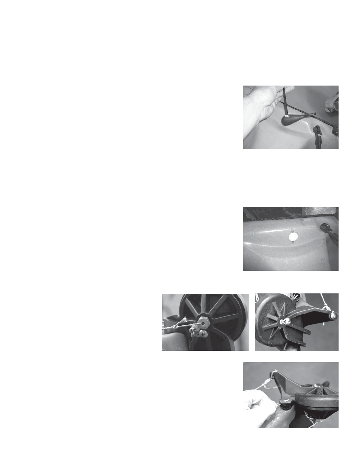
1. Using an Allen key wrench, unscrew the bolt that is passing
through that handle and pull the handle off of the control arm shaft.
2. Push the control arm shaft in so that it falls in the hull. Reach inside the hull and grab the control
arm to take both of the lines off of it. This part is to be removed from the hull as it won’t be needed
anymore. Also, untie the bungee cord and loop of line from the small spectra lines.
3. Plug the hole that is created with the push in cap that is
included with this kit.
4. To install the new tubes and lines, you
will need to partially disassembly the rudder housing. Start by loosening the screws
and unwrapping the lines completely from
the two screws on the underside of the rudder and the one screw on top of the rudder
near the main bolt.
5. Pull on the lines that exit the hull so that they completely pull
out of the rudder housing.
Page 2
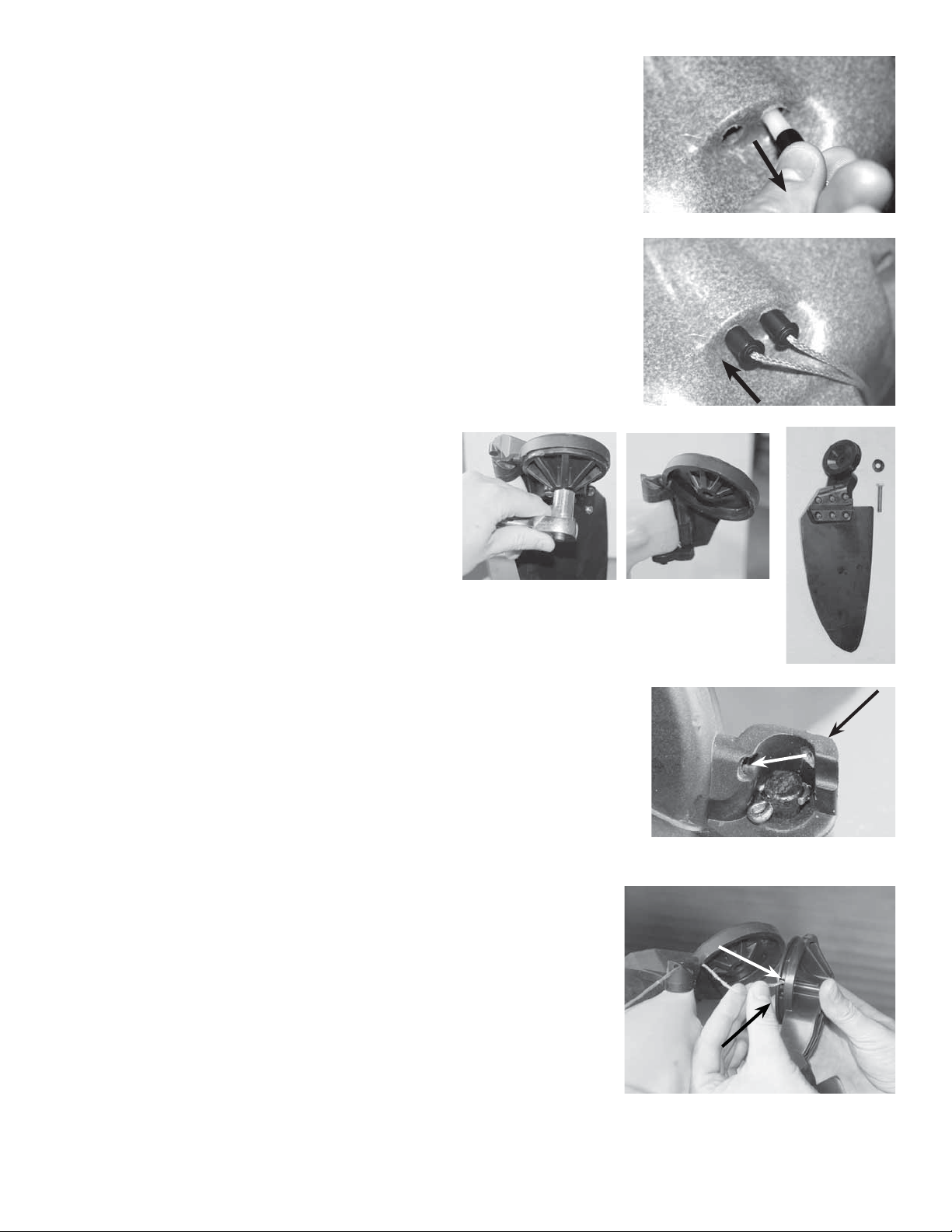
6. With the up and down control lines loose, pull on them and remove them from the hull with the tubes. If they get hung up inside
the hull, you can cut whatever is preventing you from taking out
the lines. You will no longer need these lines and tubes with this
kit.
7. With the old tubes and lines removed, install the new tubes with
lines that are in this kit into the holes that you just removed the old
tubes from. Getting the end fittings into the holes will be a tight
squeeze, so you may need a small hammer to tap them into the
holes so that they are fully installed. IMPORTANT: When these
lines are installed, the right line will be for the DOWN control
and the left line will be for the UP control.
8. Use a socket or a wrench and unthread the
bolt that passes through the center of the rudder housing. This will allow the rudder to come
apart.
9. Feed the DOWN control line through the two holes that are just
above the rudder pin. When installed, the line will come on the
inside of the rudder housing.
10. Feed the DOWN control line into the upper hole on the rudder
part of the assembly and tie a knot in the end of the line to keep it
from pulling through.
Upper Hole
Lower Hole
Page 3
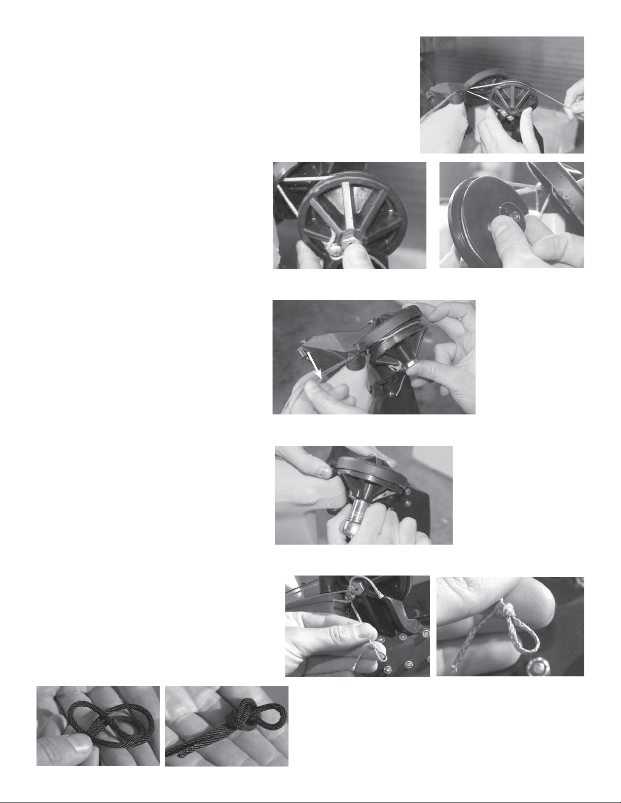
11. Now feed the UP control line through the same two holes above
the rudder pin to the inside of the rudder housing. Wrap the line so
that it goes over top and around the drum. Insert the end of the line
into the lower hole indicated in step 10 and tie a knot at the end of
the line.
12. Slide the bolt through the rudder portion of the assembly and place the plastic
washer over the threaded end. Insert
then end of the bolt into the housing and
bolt the rudder assembly back together.
As you insert the rudder half into the
housing, you have to be careful to not
allow the rudder lines fall off the track
around the circular rudder drum. To prevent this, pull up on the up/down control
lines that are exposed on the deck to
remove the slack and keep the lines tight
around the drum.
Thread in the bolt to hold the two halves
together. IMPORTANT NOTE: DO NOT
SCREW DOWN THE BOLT SO THAT
IT IS TIGHT. YOU ACTUALLY WANT IT
TO BE A FAIRLY LOOSE CONNECTION
ALLOWING AN 1/8”-1/4” OF
MOVEMENT. IF IT IS TOO TIGHT, THE
RUDDER WILL NOT GO UP PROPERLY.
13. Take the ends of the lines that you fed
through the rudder and make the loop so
that it is small enough to pass a screw head
through. The size of the loop isn’t that critical, but do not make it any more that 3/4”
big. See the pictures below on how to tie
the knot needed for this loop
Page 4

14a. Place the loop around the screw and thread the screw back into
the rudder.
14b. Follow the sample procedure with other screw and control line.
14c. Once the loops are held down with the screw, leave these lines alone for a bit and finish up the
instructions below.
15. Locate the cleat in the kit and place it on the right side of the
kayak along the forward edge of the map pocket. Center the middle
of the cleat to the point of the corner of the rails. Draw a small dot
on the kayak to locate a drilling location. The hole location should be
slightly below the top of the cleat jaws.
16. Drill a hole in the dotted location with a 5/16” drill bit
17. Insert one of the two the small
length of rigid tube into the hole and
press the black fitting at the end of the
tube into the hole. It will be a tight fit,
so you may need to give it a couple
taps with a hammer to get it into the
hole.
Drill
Location
Page 5

18. Locate the cleat on the right side map pocket just like in step
7 and use the holes in the cleat as a guide to drill two 11/64” holes
through the map pocket frame and kayak hull material underneath
it. Make sure to center the cleat along the width of the map pocket
frame so that it rests on a nice flat surface.
19. Place the padeye fitting over the cleat. Using the provided hardware, through bolt the cleat to the kayak. You will need to reach inside of the middle hatch to put on the washers and nuts on the inside
of the kayak.
20. Drill a hole and insert the other tube in the opposite side of
the kayak as well. A cleat will not be installed on the left side of
the boat, but using the same location on the map pocket corner as
you drilled on the right side is a good reference.
21. Remove the nuts that bolts on the block that routes the
mainsheet back to the forward deck mounted bar. The screws
themselves don’t need to be removed, so just take off the nuts.
22. On the opposite side of the kayak where the mainsheet
routing pulley is, you will need to drill two holes. Using a block
in the kit as a drilling guide, drill two holes so that the rearmost hole is 5” in front of and 3” down from the brackets on the
forward deck mounted bar so that the holes are symmetric with
the holes on the other side of the kayak.
Page 6

23. Through bolt the two pulleys on the inside of the kayak.
On the RIGHT side of the kayak, use the existing screws that
are being used to attach the mainsheet routing pulley line and
place nuts on the outside of the new block to hold it in place.
On the LEFT side of the kayak, use the new screws and nuts
in the kit and bolt it through the holes that you drilled. When
mounting the blocks make sure to take note that there is a
larger gap on one side of the pulley which should be located toward the bow of the boat as shown in the pictures (see arrow).
24. Locate the two line assemblies which have the webbing
scrunched along the length of the line. Take note of the section of the line that has a longer length of line after the webbing
attached to the line.
25. Take the end of the line that has a longer length after the
webbing and feed it up through the bottom and around the
pulley. Continue to feed that line back to the tubes that you
pressed in on step 9 and 12 and feed it through the tube so
that it exits the hull. Do this on both sides of the kayak so
that both of the pulleys that you bolted to the kayak have lines
wrapping around them and coming out through the tubes.
Kayak Bow
26. Take the ends of the line and feed them through the “T” handles. Tie a simple knot as close to
the ends of the lines as possible and pull the knots into the handles.
27. With the one end of the lines tied to the “T” handle, pass the other ends of the line along the side
of the kayak so that it runs all the way to the stern. You will need to reach inside of the middle hatch
to help pass them down the length of the kayak. It is important that the line is passing on the outside
of any of the inside features like the mirage well, daggerboard well and cart scuppers.
Page 7

28. Pull the lines all the way back to the rear hatch and tie a simple
knot approximately 4” from the end of the lines.
29. Now you are going to lock the small lines with loops at the end coming from the rudder to the
knots that you just tied. To do this, follow the diagram below to form a cinch around the line up to the
knot. Make sure that you know what line is the up and which is the down line coming from the
rudder. To do this pull on the rudder lines to see what one start to pull the rudder up. The line
that makes the rudder go UP should be attached to the line running along the left side of the
kayak.
The system should look like the diagrams below.
Pulley
Small Tubing
Webbing
T Handle
Rudder Line and
Larger Line Connection
Page 8

DOWN CONTROL LINE
T Handles
Pulleys
UP CONTROL LINE
29. Your up/ down rudder system is now ready to go
a. Pull on the right “T” handle to lower the rudder. Pull
the line tight and cleat off to hold it in the down position.
b. To raise the rudder, uncleat the lock down line and pull
the “T” handle on the left side of the boat. IMPORTANT!
When the rudder is in the locked down position, it will
have some flexibility in the system due to stretch in
the rope, but it should be uncleated and raised prior
to beaching.
Webbing
Rudder Line and
Larger Line Connections
30. Place the stickers on the “T” handles to label which one does what. The “UP” sticker should go
on the left handle and the “DOWN” sticker should go on the right handle. To ensure a good adhesion,
make sure that the handles are clean of any water or debris.
 Loading...