

Page 1
= HOBIE 17
_c
_ccc
_cc
_c
_ccc
.
_c
-
--"""",..'WCC%%X wc""cccccc'c""" C" c_-"',"',-
""C-CC=-."'-""""""" cc,ftc""
S'c
SE'
MB LY""""c M" c " ""'C,'C"C"",,,
"'--"",,'c
--"'""--"',,,'c','c, """,- ' C"', -""", """,-",,"', :::=---
MA' NUAL[1..11.1_"'" " ,,"'c_-
,;
Page 2

Introduction
Welcome to the Robie Cat family of sailors. Thanks for joining us. By purchasing the
Robie 17, you are treating yourself to the ultimate in single hand sailing enjoyment.
Even if you have long experience with sailboats or if you have owned Robie Cats in the
past, please read this manual thoroughly. It will give you easy, accurate instructions on
assembling your new boat. We suggest reading through the manual completely before you
begin assembly. Pay special attention to the boat and parts descriptions shown on the follow-
mg pages.
If you are new to sailing, this manual will not teach you how to sail. There are many
excellent courses and books available on the safe handling of small sailboats. Contact your
Robie dealer or local Coast Guard Auxiliary for recommendations on courses in your area.
They'll be happy to help. For your information, we have included a toll-free number on page
25 which will enable you to learn more about courses in your area.
Please remember to obey the most important rule of all when assembling your boat stay away from overhead power lines! Before starting to rig your boat, thoroughly examine
the area for power lines and report any potentially hazardous power line that you see by
writing to the reponsible utility company, send a copy to Robie Cat Bounty Program, P.O.
Box 1008, Oceanside, CA 92054 and sail elsewhere. Remember, CONTACT OF A MAST
WITR A POWER LINE COULD BE FATAL.
The Robie 17 is made with the innovative ComptipTM mast tip (U.S. Pat. No. 4,597,346).
This is an essentially non-conducting composite tip which can help prevent electrocution and
boat damage from mast/power line contact. Robie Cat worked many years to develop this
new tip so that it would be as effective as possible. Still, nothing can pro'vide total protection
at all times, so it's best to avoid wires. Be sure to read the "Maintenance" section to find out
how to protect the tip's insulating ability.
By following the instructions, maintaining your new boat properly and observing safety
rules, we're confident you'll receive many years of sailing enjoyment from the Hobie 17.
-1-
Page 3
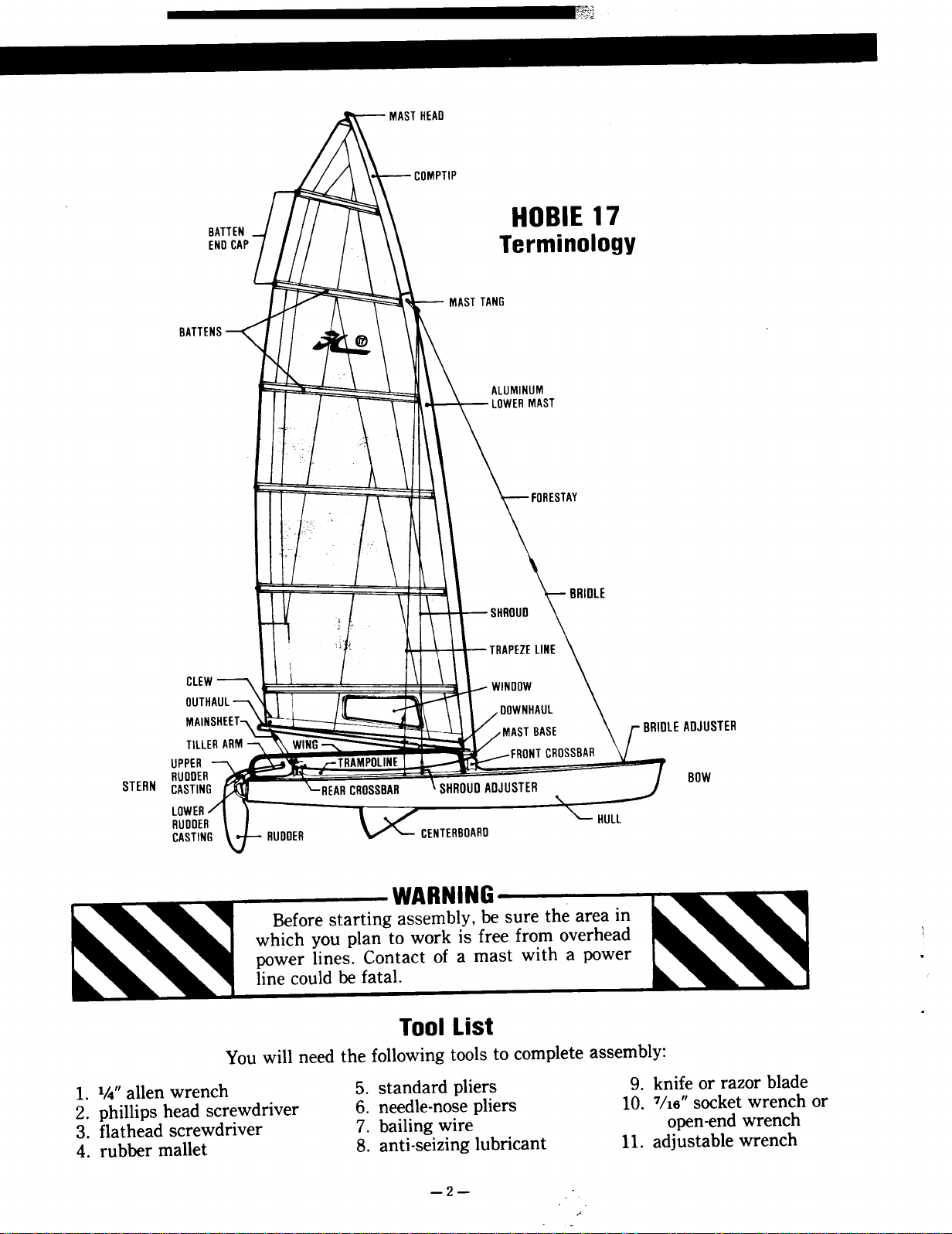
BAT
COMPTIP
MAST TANG
~
HOSIE 17
Terminology
ALUMINUM
lOWER MAST
SHROUD
TRAPEZE LINE
ClE
OUT
MAl OOWNHAUl
MAST BASE LE ADJUSTER
Till
UPPER FRONT CROSSBAR
STERN CASTIN BOW
RUOOE
lOWER
RUOOE
CASTIN
WARNING
Before starting assembly, be sure the area in
which you plan to work is free from overhead \
power lines. Contact of a mast with a power .
line could be fatal.
Tool List .
You will need the following tools to complete assembly:
1. 1/4" alIen wrench 5. standard pliers 9. knife or razor blade
2. phillips head screwdriver 6. needle-nose pliers 10. 7/16" socket wrench or
3. flathead screwdriver 7. bailing wire open-end wrench
4. rubber mallet 8. anti-seizing lubricant 11. adjustable wrench
-2"
Page 4
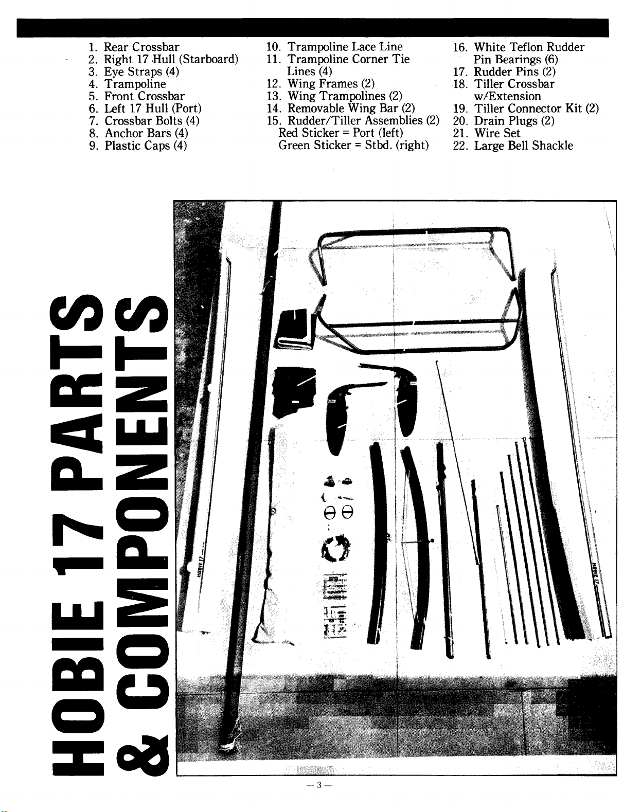
1. Rear Crossbar 10. Trampoline Lace Line 16. White Teflon Rudder
2. Right 17 ,Hull (Starboard) 11. Trampoline Corner Tie Pin Bearings (6)
3. Eye Straps (4) Lines (4) 17. Rudder Pins (2)
4. Trampoline 12. Wing Frames (2) 18. Tiller Crossbar
5. Front Crossbar 13. Wing Trampolines (2) w/Extension
6. Left 17 Hull (Port) 14. Removable Wing Bar (2) 19. Tiller Connector Kit (2)
7. Crossbar Bolts (4) 15. Rudder/Tiller Assemblies (2) 20. Drain Plugs (2)
8. Anchor Bars (4) Red Sticker = Port (left) 21. Wire Set
9. Plastic Caps (4) Green Sticker = Stbd. (right) 22. Large Bell Shackle
cncn
~Z
~~
D. Z .aii.
= ~'e
r- a. (,
'_11_- "
~ )11'- 1,.
mu
& i i~l.ft ".c:_"
ii'l~
~
Q ~~
.I T.",~ '1 ;;"'..
Q
za8
-3-
Page 5
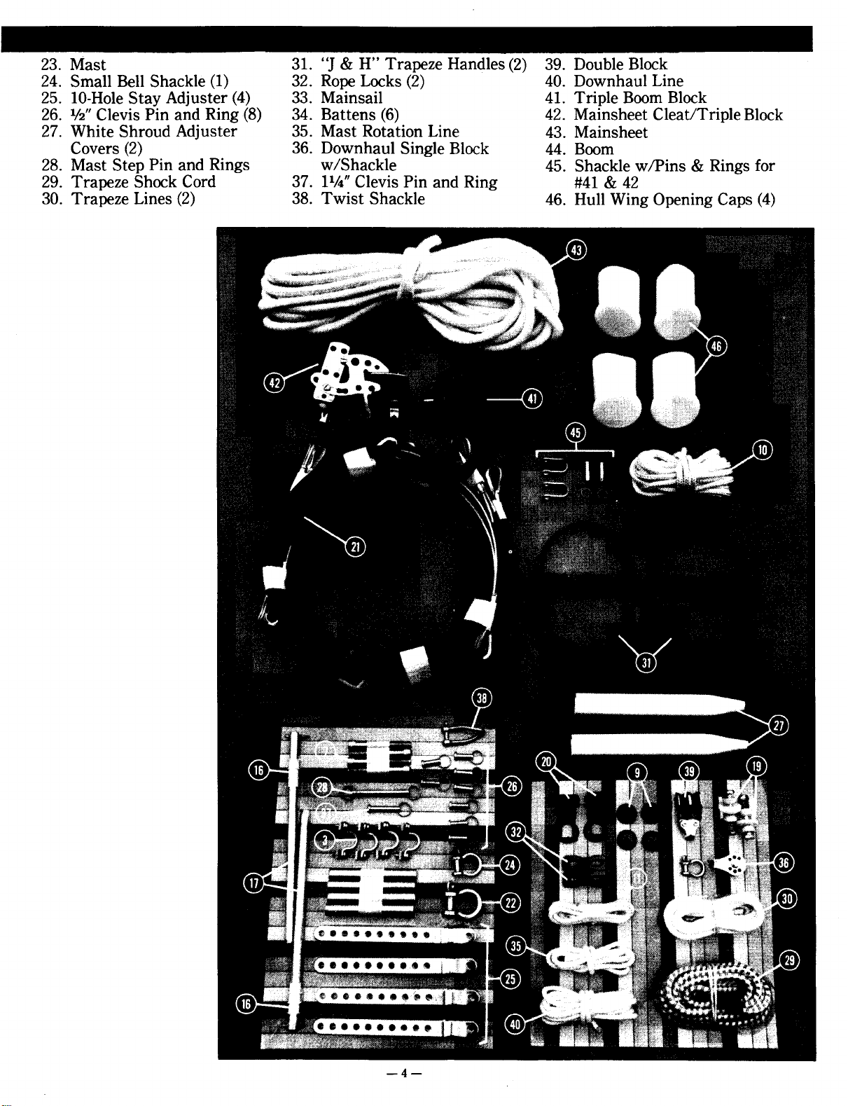
23. Mast 31. "J & H" Trapeze Handles (2) 39. Double Block
24. Small Bell Shackle (1) 32. Rope Locks (2) 40. Downhaul Line
25. 10-Hole Stay Adjuster (4) 33. Mainsail 41. Triple Boom Block
26. 1/2" Clevis Pin and Ring .(8) 34. Battens (6) 42. Mainsheet Cleat/Triple Block
27. White Shroud Adjuster 35. Mast Rotation Line 43. Mainsheet
Covers (2) 36. Downhaul Single Block 44. Boom
28. Mast Step Pin and Rings w/Shackle 45. Shackle w/Pins & Rings for
29. Trapeze Shock Cord 37. 11/4" Clevis Pin and Ring #41 & 42
30. Trapeze Lines (2) 38. Twist Shackle 46. Hull Wing Opening Caps (4)
-4-
Page 6
HOBIE 17 ASSEMBLY MANUAL UPDATES
The following items have been changed or re-designed.
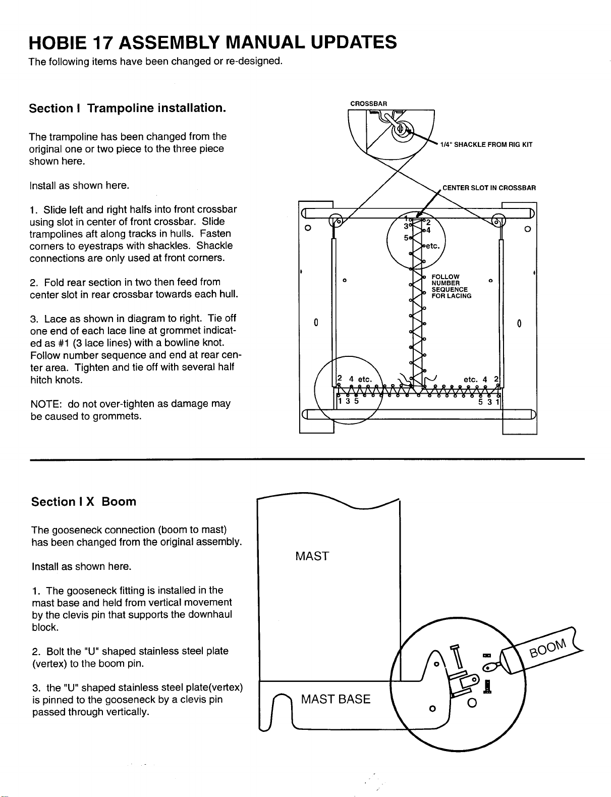
Section I Trampoline installation. CROSSBAR
The trampoline has been changed from the
original one or two piece to the three piece
shown here.
Install as shown here.
1. Slide left and right halfs into front crossbar
using slot in center of front crossbar. Slide
trampolines aft along tracks in hulls. Fasten
corners to eyestraps with shackles. Shackle
connections are only used at front corners.
2. Fold rear section in two then feed from 0 0
center slot in rear crossbar towards each hull.
3. Lace as shown in diagram to right. Tie off 0
one end of each lace line at grommet indicat- 0
I .
ed as #1 (3 lace lines) with a bowline knot.
Follow number sequence and end at rear center area. Tighten and tie off with several half
hitch knots.
NOTE: do not over-tighten as damage may
be caused to grommets.
Section I X Boom
The gooseneck connection (boom to mast)
has been changed from the original assembly.
Install as shown here.
1. The gooseneck fitting is installed in the
mast base and held from vertical movement
by the clevis pin that supports the downhaul
block.
MAST
2. Bolt the "U" shaped stainless steel plate
(vertex) to the boom pin.
3. the "U" shaped stainless steel plate(vertex)
is pinned to the gooseneck by a clevis pin MAST BASE
passed through vertically.
Page 7
Assembly Instructions
I. Frame and Vinyl Trampoline
Assembly Instructions
(See page 8 for mesh trampoline instructions.)
Note ~':
All directions referring to "right," "left,"
"front" and "back" are based on looking from
the stern toward the bow.
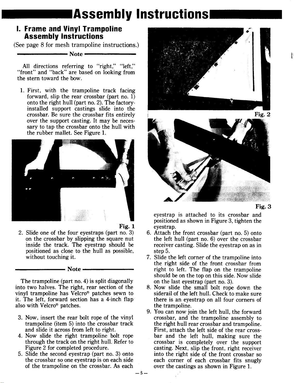
1. First, with the trampoline track facing
forward, slip the rear crossbar (part no. 1)
onto the right hull (part no. 2). The factoryinstalled support castings slide into the
crossbar. Be sure the crossbar fits entirely Fig. 2
over the support casting. It may be necessary to tap the crossbar onto the hull with
the rubber mallet. See Figure 1.
Fig. 3
eyestrap is attached to its crossbar and
positioned as shown in Figure 3, tighten the
Fig. 1 eyestrap.
2. Slide one of the four eyestraps (part no. 3) 6. Attach the front crossbar (part no. 5) onto
on the crossbar by slipping the square nut the left hull (part no. 6) over the crossbar
inside the track. The eyestrap should be receiver casting. Slide the eyes trap on as in
positioned as close to the hull as possible, step 5.
without touching it. 7. Slide the left corner of the trampoline into
the right side of the front crossbar from
Note right to left. The flap on the trampoline
should be on the top on this side. Now slide
The trampoline (part no. 4) is split diagonally on the last eyestrap (part no. 3).
into two halves. The right, rear section of the 8. Now slide the small bolt rope down the
vinyl trampoline has Velcro@ patches sewn to siderail of the left hull. Check to make sure
it. The left, forward section has a 4-inch flap there is an eyestrap on all four corners of
also with Velcro@ patches. the trampoline.
9. You can now join the left hull, the forward
3. Now, insert the rear bolt rope of the vinyl crossbar, and the trampoline assembly to
trampoline (item 5) into the crossbar track the right hull rear crossbar and trampoline.
and slide it across from left to right. First, attach the left side of the rear cross-
4. Now slide the right trampoline bolt rope bar and the left hull, making sure the
through the track on the right hull. Refer to crossbar is completely over the support
Figure 2 for completed procedure. casting. Next, slip the front, right receiver
5. Slide the second eyestrap (part no. 3) onto into the right side of the front crossbar so
the crossbar so one eyestrap is on each side each corner of each crossbar fits snugly
of the trampoline on the crossbar. As each over the castings as shown in Figure 1.
-5-
Page 8
CAUTION Note
Before completing step 1.0, check the threads Once the boat has been sailed a few times it
of the crossbar bolts (part no. 7) by hand screw- takes on "normal set." In other words, the
ing them into each anchor bar (part no. 8). If crossbar and hulls will set and need retightenthe bolt will not thread easily, use a tap and die ing. This setting also occurs after trailering
to clear the threads. Use an anti-seizing lubri- any long distance. This tightening procedure
cant such as Never-SeeZi!J to help prevent cross- should be performed periodically.
threading and galling.
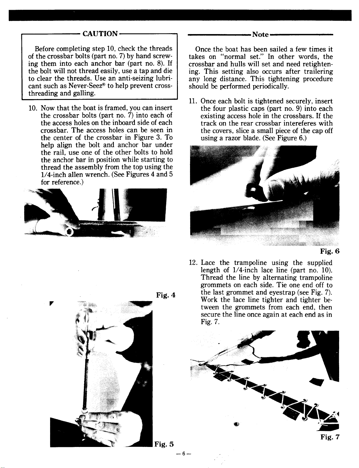
11. Once each bolt is tightened securely, insert
10. Now that the boat is framed, you can insert the four plastic caps (part no. 9) into each
the crossbar bolts (part no. 7) into each of existing access hole in the crossbars. If the
the access holes on the inboard side of each track on the rear crossbar intereferes with
crossbar. The access holes can be seen in the covers, slice a small piece of the cap off
the center of the crossbar in Figure 3. To using a razor blade. (See Figure 6.)
help align the bolt and anchor bar under
the rail, use one of the other bolts to hold
the anchor bar in position while starting to
thread the assembly from the top using the
1/4-inch alIen wrench. (See Figures 4 and 5
for reference.)
Fig. 6
12. Lace the trampoline using the supplied
length of 1/4-inch lace line (part no. 10).
Thread the line by alternating trampoline
grommets on each side. Tie one end off to
" . Work the lace line tighter and tighter be-
. tween the grommets from each end, then
Fig 4 the last grommet and eyestrap (see Fig. 7).
secure the line once again at each end as in
Fig. 7.
~~ ...
~ ~"4i
!!') ""'11.~ ':'~
., »~
- _~I
Fig. 5
Fig. 7
-6-
Page 9
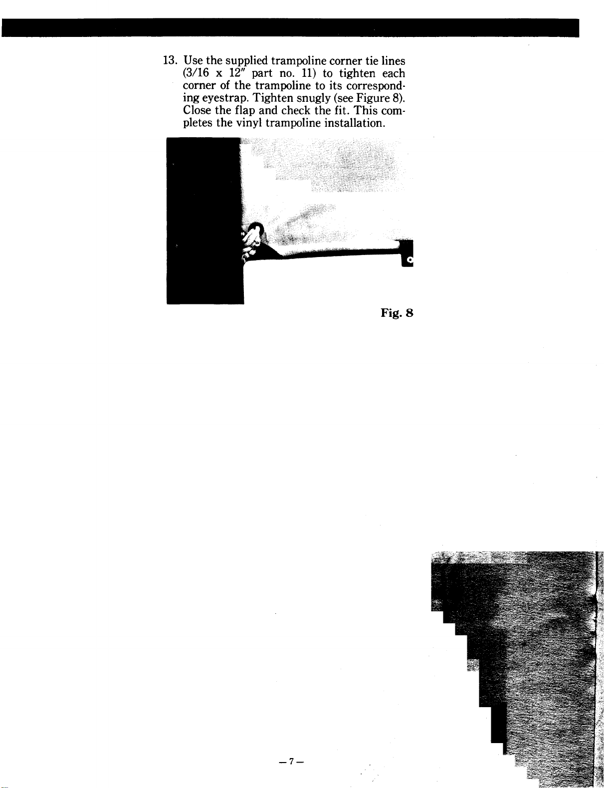
13. Use the supplied trampoline corner tie lines
(3/16 x 12" part no. 11) to tighten each
corner of the trampoline to its correspond-
ing eyestrap. Tighten snugly (see Figure 8).
Close the flap and check the fit. This com-
pletes the vinyl trampoline installation.
Fig. 8
-7-
Page 10

II. Frame and Mesh TrampolineNote
Note Placing the bows in a slightly toed-in position
will make sliding the trampoline easier.
The one-piece mesh trampoline installs with
the lacing grommets on the side closest to the 8. Slide the front crossbeam onto the tramporear crossbar. The side with grommets nearest line bolt rope suspended between the hulls.
the crossbar, is the rear portion of the trampo- 9. Slide each front eyestrap on either side of
line. the front crossbar so one is at each end.
All directions referring to "right," "left," 10. Spread the bows apart slightly and insert
"front" and "back" are based on looking from one side of the crossbar over its receiver.
the stems toward the bows. Then slip on the other side. Use the rubber
mallet to snug each side onto its receiver.
1. First, with the trampoline track facing 11. Attach the crossbar bolts as described in
forward, slip the rear crossbar (part no. 1) steps 10 and 11 of section I.
onto the right hull (part no. 2). The factoryinstalled support castings slide into the
crossbar. Be sure the crossbar fits entirely Note
over the support casting. It may be neces-
sary to tap the crossbar onto the hull with Once the boat has been sailed a few times it
the rubber mallet. See Figure 1. takes on "normal set." In other words, the
2. Slide one of the four eyestraps (part no. 3) crossbar and hulls will set and need retightenon the crossbar by slipping the square nut ing. This setting also occurs after trailering
inside the track. The eyestrap should be any long distance. This tightening procedure
positioned as close to the hull as possible should be performed periodically.
without touching it.
3. Slide the mesh trampoline (part no. 4), with 12. Secure the trampoline comers as in step 13,
the grommets aft, into and across the rear section I.
crossbar (part no. 1).
4. Slide the second eyestrap (part no. 3) into This completes assembly of mesh trampo-
position so there is one at each comer of lines.
the trampoline. Tighten the eyestraps.
5. Slip the left side of the rear crossbar onto
the left hull. You may need to use the
rubber mallet to tap the assembly snug.
CAUTION
Before completing step 5, check the threads
of the crossbar bolts by hand screwing them
into each anchor bar by hand. If the bolt will
not thread easily, use a tap and die to clear the
threads. Use an anti-seizing lubricant such as
Never-Seez@ to help prevent crossthreading and
galling.
6. Drop in each of the rear crossbar bolts into
each side of the crossbar. DO NOT attach
the anchor bars (part nos. 7 and 8).
7. Slide both sides of the trampoline up both
siderail grooves simultaneously.
-8-
Page 11

III. Vinyl and Mesh Wing
Trampolines
Both mesh and vinyl wing trampolines assem-
ble in the same way.
1. Lay one wing frame (part no. 12) alongside
each hull as if they were being inserted
into the hulls to make it easier to identify
each side. The steeply angled end of each
wing should be facing toward the sterns.
2. Lay the wing trampoline (part no. 13)
beside each wing frame to verify the correct side as in Fig. 9. Fig. 10
3. Slide the wing trampolines onto the front
end of the wing frame. Be sure to slide all
three sections onto the frame.
I
Fig. 9 frame, slide the wing frame compression
Note
The wing sleeve will only fit when you start
installing it from the front end of the wing
frame. Look closely at the frame and you'll
notice one end has a casting which extends
further from the frame. The sleeve of the trampoline will not slide over this casting. (See Figure 10.) Slide the sleeve on from the side shown
in Figure 11.
Fig. 11
4. Once the wing tramp is fitted over the wing
bar (part no. 14) through the trampoline
opening as in Fig. 12. Attach the opposite
end over the casting.
Fig. 12
5. The wing now must be sprung enough to
allow the compression bar to slip over the
opposite casting. Use your foot to spread
the wing apart slightly. Slip the compression bar over the casting and slowly release
-9-
Page 12

tension. Repeat this step on the other wing.
(See Fig. 13.)
Fig. 13
6. Now set the wings aside while completing
the rest of the assembly.
This completes the wing frame and trampo-
line assembly.
-10-
Page 13

IV. Rudder and Tiller Crossbar 3. Repeat these steps on the other rudder
Assemblies assembly.
4. Attach the left end of the tiller crossbar
(part no. 18 marked with a red tag) to the
Note left rudder arm using one of the tiller con-
necting assemblies (part no. 19) by insert-
The rudder assemblies (part no. 15) are ing the connector bolt through the tiller
marked with red and green tags. Red tags stand crossbar to the tiller arm.
for left side assembly while green stands for 5. Place the flat washer over the threads of
right side. To help make assembly easier, place the bolt followed by the delrin half-round
all items marked with a red tag behind the left washer. Then place the crossbar arm on
stern and green-tagged items behind the right. top of the white delrin washer located
Do not mix differently tagged items. The fol- between the connector arm and the tiller
lowing steps are identical for both assemblies. arm. Refer to Fig. 15.
Note
The rudder castings are installed with three
small, white teflon bearings (part no. 16) which
are placed in the casting where the rudder pin
slides through the casting. These bearings fit
between the rudder pin and the casting with
one on the top of the bottom casting and two in
the upper casting.
1. Grasp one of the rudder pins (part no. 17)
so the end with the small hole and cotter
pin faces up. Remove the cotter pin. Slide it F. 15 F. 16
through both the lower rudder casting Ig. Ig.
bearings and the gudgeo~ as. well as the 6. Then place the opposite white delrin washer
~pper assembly as show~ m FIg. ~4.. When over the bolt threads followed by the washer
mserted: the small hole m the pm should and spring. Secure the assembly with the
app~ar Just above the top of. the ru~der Nylock nut. Tighten the nut to prevent the
cast~ng. Be sure the small whIte bearIngs assembly from vibrating or backing out.
are m place. See Fig. 16.
2. Insert the supplied cotter pin into the
rudder pin hole and bend the cotter pin to
prevent rudder pin from backing out of the CAUTION
casting: Refer to Fig. 14.
Be sure the nut is threaded past the nylon
portion of the bottom of the nut by one complete thread as illustrated in Fig. 17.
Fig. 14
-11-
Page 14

Fig. 17
7. Repeat steps 4 through 6 on the other side
of the tiller crossbar.
This concludes assembly of the rudders and
tiller crossbar.
-12-
Page 15

V. Drain Plugs
Both plugs (part no. 20) are the most often
forgotten item during rigging, but among the
most important. Even championship sailors
forget to put thejr drain plugs in once in a
while, but you can't go very far with them out. i
Be sure to check your drain plugs before you
leave shore. Be sure you have gaskets in place
and no sand, or other debris which can permit
leakage, around the opening. Drain plug location is next to the lower gudgeon as shown in
Figure 14.
VI. Mast Rigging, Raising and
Lowering
r""""""""""""~ WARNING r""""""""""1 Fig. 18 Fig. 19
I I 5. Attach each of the two ten-hole stay adjus..
I ~efore starting assembl.y, be sure the area in ~ ters (part no. 25) to the bow anchor pi~s.
~ whIch ~ou plan to work IS free fro.m overhead I Pin the stay adjuster to the anchor pInS
~ power lInes. Contact of a mast wIth a power I with the single open end down. For refer-
I line could be fatal. I ence, see Figure 28. . .
~ "..." 1 6. Attach each of the two remaInIng ten-hole
. stay adjusters (part no. 25) to the each hull
Note at the chain plate anchor pin. Pin the stay t
The WIre set for the Hoble 17 consIsts of the open end down. For reference, see Figure
following: Trapeze wires; Shrouds; Forestay; 21. j
Bridles. The trapeze ':lires and the .l~ft and 7. The main halyard (70' x 3/16" line) should
right shrouds are unIversal. In addItIon, all be threaded through the top of the mast '
three forestay/bridle wires are the same length. and back down through the middle sheave :
1. Uncoil the supplied wire set (part no. 21) now. Check the halyard shackle and ring to
. .. adjusters to the anchor pins with the single
at the base of the mast. If it is not, thread it
and. lay the wires on the groun.d in the fol- be sure they are attached to the end exiting I
loWIng pattern from left to rIght: a. left the mast head. ,
trapeze wire, b.. left s~roud wi~e, c. one of 8. Check the main halyard shackle and ring.
the forestay/brldle WIres, d. rIght shroud Make sure the halyard is securely tied with
wire, e. right trapeze wire. a halyard knot as described. (See "Knots"
2. Slide the wir~s onto the large bell shackle on page 17.) Be sure the halyard ring has a
(part no. 22) m the same pattern as they twist shackle attached to it.
were laid out in step 1. Then attach the
shackle to the mast tang (part no. 23). Be
sure the trapeze wires are attached so the Note
handle end is not the end closest to the
tang. Refer to Fig. 18. Make sure the knot is as small as possible so
3. Secure the shackle pin to the shackle with the ring will be able to clear the halyard hook
bailing wire. Tie the shackle to the pin, to when fully hoisted as seen in Fig. 20. The knot
prevent the pin from backing out. shown is much larger than that described on
4. Use the small bell shackle (part no. 24) to page 17. Use the halyard knot.
attach the two bridles to the forestay.
Securely tighten the shackle with pliers 9. Tie a figure-eight knot (see "Knots" on
(see Fig. 19). page 17) at the bare end of the halyard.
-13-
Page 16

.. I Before raising the mast, be sure the area is I
..,~-"_..,',."._"
Fig. 20 Fig. 21
CAUTION
r"""""""""""""""". W ARNIN G """""""""""""""""1
. free from overhead power lines. Contact of a I
I mast with a power line could be fatal. I
, ~
15. Locate the mast step pin (part no. 28) from
the mast base or rig kit.
16. Rotate the mast so the arrows are aligned
and slip the mast base over the mast step
ball. Then insert the step pin. Secure the
pin in place by inserting the ring through
the hole in the end of the pin. (See Fig. 22
ring not secure.)
~l
Be sure the mast tip is supported by a rear
mast support, a box, a ladder or a friend so its
weight does not lay on the tiller crossbar or
directly on the boat during the following procedure.
Fig. 22
10. Position the mast so the mast tip points 17. To raise the mast alone, attach the shackle
toward the sterns and the mast base is end of the main halyard to the right bow's
next to the mast step ball on the forward ten-hole adjuster (Fig. 27), being certain it
crossbar so the yellow arrows are aligned, passes over both the left and right shrouds,
Check both shroud wires to be sure they trapeze wires and the forestay.
are not fouled or wrapped around the mast.
11. Now slip the white shroud covers (part no.
27), thimble end first, over each shroud CAUTION
cover through the smallest opening in the
end of the cover. The first time you try to raise the mast, have
12. Attach both left and right shrouds to the the help of two friends available. Also check the
ten-hole stay adjusters on corresponding gooseneck to be certain it is not positioned at an
sides of the boat. Place each shroud wire in angle forward or away from the top of the
r the st.ay adjuster and insert the clevis pin mast. !f .it is, tilt or ti,e it to the rotation arm to
\ and rIng (part no. 26). Use the fourth hole prevent It from touchIng the front crossbar dur-
f Figure 21.)
from the top of each stay adjuster. (See ing raising. '
13. Clear each trapeze wire so they are not
fouled around the opposite shroud or the ~ WARNING """""""""""""""""i
forestay. I I
14. Check the forestay to be certain it is not. Before raising the mast, be sure the area is I
fouled around the shrouds during the mast. free from overhead power lines. Contact of a I
raising. Be sure it remains clear. I mast with a power line could be fatal. I
' 1.
-14-
Page 17

18. Step onto the trampoline and place your
foot on the rear crossbar.
19. Keeping all the weight on that foot, lift the
mast being sure to keep it rotated so the
yellow arrows are aligned. Refer to Fig. 23. t-
.
I
Fig. 26
with one hand to stabilize the mast once it
is completely up, while you perform the
next step with the other hand..
22. Take up the slack in the main halyard (Fig.
. . . mast rotation bar or the mast base, which-
20. S~I~g your arms over your head .while ever is most comfortable for you. Tie it
shIftIng your body under the mast. (FIg. 24) very securely with a double or triple hitch
Fig 23 27) and secure the main halyard to the
(see "Knots" on page 17). Remember, the
knot you tie here will have to support the
total weight of the mast once you release
forward pressure. Due to the distance and
characteristics of the line, try to pull some
stretch into it.
Fig. 24
21. Push the mast up and over your head, then
walk it forward grasping hand-over-hand
as you go. (Figs. 25, 26) If you are raising
the mast alone, maintain forward pressure
Ig. - 15 -
<II
Fig. 27
23. When you're certain the halyard is secure,
walk forward, clear the bridles of any
wraps and attach the cleared bridle to the
ten-hole adjuster you installed during step
6 of chapter VI. Insert the clevis pin and
Page 18

ring (part no. 26), using the fourth hole
from the top. (Fig. 28)
J . '"
. " ~~ "
5w.. ",,"
Fig. 28
24. Now slowly release the main halyard. Let
about 2 feet of the halyard line run through
the sheave and tie the rest securely to the
mast rotation bar or the mast base as in
step 23 of this chapter. The angle of the
mast will shift from left to right as the load
is shifted from the main halyard to the side
bridle wire.
25. Locate the other bridle wire. Clear the bridle of any wraps and attach the cleared
bridle to the right ten-hole adjuster you
installed during step 6 of this chapter VI.
Insert the clevis pin and ring (part no. 26),
using the fourth hole from the top.
26. Release the twist shackle endot1temain
halyard from the right ten-hole adjuster.
27. Secure the shackled end of the main halyard to the boat to prevent it from slipping
to the top of the mast accidentally.
-16-
Page 19

VII. Trapeze Wires
1. Lead the trapeze shock cord (part no. 29)
through the grommet on the forward outboard side of the trampoline, then under
the trampoline and through the opposite
grommet.
2. Clear the trapeze handles so they lead to
the outside of the shrouds. Then tie the 3foot length of quarter-inch line (part no. 30)
to the dogbone or the J and H handle
(optional) with a bowline knot. After the
line is led through the thimble on the end
of the trapeze wire, attach the rope lock
(part no. 32). Now tie the end of the line to
the shock cord with another bowline knot.
(The complete assembly is shown in Fig.
29.)
-17-
Fig. 29
~
r
Page 20

VIII. Sail and Battens shackle tightly. Feed the sail luff through
the sail feeder on the mast (Figure 31). Use
1. Spread the sail (part no. 33) out flat on the the halyard to gradually pull the sail up
ground and lay each batten (part no. 34) while guiding the luff into the feeder. If the
over the correct batten pocket. sail binds at the feeder, back it down a bit,
then continue pulling it up.
CAUTION
It's important that the sail be perfectly flat
on the ground. A wrinkled sail could lead to a
tear in the sail fabric when the battens are
pushed into their pockets.
Note
When battens are laid over the correct pocket,
two to three inches of the batten end should be
laying over the outer edge of the sail.
2. Start at the top of the sail and insert each
batten into its pocket being sure that the
end of the batten with the flat end cap slips
in first.
3. Tie each batten snugly with the batten ties .
as shown in Figure 30. (Batten ties have .
been attached to the corner of the sail FIg. 31
before shipping.) Battens are at the correct 6. When the sail nears the halyard hook at
tightness when the batten has removed the the top of the mast, gently pull the sail up
wrinkles from the pocket. Proper tension and listen for a slight "click" as the ring
will vary with wind conditions. passes the small hook. (See Fig. 32) Then
'I rotate the mast to the right by pushing on
, the mast rotation arm at the mast base.
Then release the halyard. When you think
it has locked, pull down on the bottom of
the sail to be certain.
Note
If you raise the sail too quickly or pull too
hard, you will slide the hook past the lock. The
ring will then slide back down past the lock
assembly. Use a gentle touch when nearing the
lock assembly and listen for the click. When
Fig. 30 disengaging the ring, pull the halyard so the
4. Point your Hobie 17 into the wind. This hook passes th~ lock, thus allowing the arm to
allows you to pull up the sail easily and close and the rIng to pass the hook.
prevents the boat from sailing away.
5. Check the halyard to be sure it is not
wrapped around the mast or shrouds. Twisting the main halyard approximately six
times in a clockwise direction may facilitate halyard locking. Then attach the halyard to the top of the sail and secure the
-18-
Page 21

Downhaul Line Rigged
~;
I:'
::
j
~!
'"
,
;
,
'-
Fig. 32
. '
FIg. 32.1
-19-
Page 22

IX. Boom
1. Hold the boom (part no. 44) with the slot
and the two cleats facing up and slip it onto
the gooseneck mast fitting. Secure the boom
with the clevis pin and ring. (Fig. 33)
Fig. 35
NOTE: Figure shows Rotation and Downhau/ Rigged.
4. Now turn to the downhaul. First, attach
the small single block (part no. 36) and
small shackle using the clevis pin and ring
(part no. 37). Place the clevis pin through
. one of the two holes on the top of the mast
FIg. 33 base casting, attach the block and shackle
2. Attach the outhaul (secured to the cleat through the pin, then push the pin through
underneath the boom) to the sail by remov- ~he second .hole in the base casting. Now
ing the pin from the outhaul shackle and Insert the rIng to secure the pin.
attaching the shackle to the third inboard 5. Use the twist shackle to attach the double
hole in the plate on the sail. (Newer models block (part no. 39) to the grommet at the
have only three holes. See Figure 34.) bottom of the sail.
6. Use a halyard knot (see "Knots" page 17) to
tie the downhaul line (part no. 40) (7' x
3/16" line) to the pin or bolt in the mast
base. Then thread the line up to and
through the double block, down to the
small sheave in the mast base casting
opposite from the bolt. Then thread the line
back up to the double block and down to
the small single block you attached in Step
4. Then take the line through the cleat
just behind the mast rotation cleat. Refer to
Figure 35 for the complete assembly. Once
the line is through the cleat, tie a figureeight knot in the end of the line.
-
Fig. 34
3. Use a bowline knot to tie the mast rotation
line (part no. 35) (3' x 3/16" line) to the
boom cleat closest to the mast. Then lead
the line through the mast rotation arm and
back through the cleat as shown in Figure
35. Once the line is through the cleat, tie a
figure-eight knot in the end of the line.
-20-
Page 23

X. Mainsheet and Traveller the small padeye on the back side of the
rear crossbar and tie a figure-eight knot to
1. Turn to the mainsheet package. First, at- secure the line. Refer ~o Figures 36 and 37
tach the triple block (part no. 41) to the for the completed mamsheet system. Rebale on the boom using the supplied shackle, ~em.ber that the system features a crossed
clevis pin and ring. lIne m the purchase.
2. Attach the mainsheet cleat and triple block
(part no. 42) to the traveller car on the rear ..
crossbar using the other supplied shackle,
clevis pin and ring.
7/16" line) from the cleat on the triple 'r"
block, through the padeye, the cleat and the 1:
center sheave (part no. 42). Then take the ,I'.:
line up to the ouside sheave on the boom
block (part no. 41), down through the outside sheave on the same side on the lower
blocks and up through the center sheave on
the top blocks. Continue stringing the end
of the mainsheet down through the last
open sheave on the lower blocks, up through Fig 37
the last open sheave on the top blocks, .
down through the small padeye on the
backside of the cleat on the lower blocks
and then secure the end of the line with a
figure-eight knot. For the complete assem-
bly, refer to Fig. 36.
.3. Lead the mainsheet (part no. 43) (42' x ""c'.
Fig. 36
4. Now rig the traveller line by using the
opposite end of the mainsheet from the one
you just tied off in step 3. Lead this end
through the swivel cleat attached to the
rear crossbar, then the bullseye and finally
through the traveller car which slides on
the rear crossbar. Take the end through
i
!
-21-
Page 24

XI. Installing the Wings 1. Place the trapeze wire and hookup outside
of the wings as in Figure 29.
Now that the entire boat is rigged, you're 2. ~o insert t~e wings, simply work the inserready to insert the wings for sailing. We've tIon tub~s Into the hull.sockets an .inc~ or
saved the wings for last to prevent you from so at a time. Push one sIde of the WIng Into
constantly having to step around them while the tube, then the other and continue
you performed the other rigging chores. .alternating until both sides are completely
Inserted.
CAUTION
It is very important that the wings be com-
pletely inserted when sailing or whenever any ~f the wings cannot be easily inserted using
load is applied to them. Failure to completely thIS syste~, check t~e.end caps for debris (such
insert the wings will result in hull and/or wing as sand), Improper fItting or metal burrs.
damage. You have inserted the wings completely when the band of tape on the outboard
side of each insertion tube aligns with the top CAUTION
of the boat deck. For correct distances, please
check drawing below. Be sure to cover the hull wing openings with
the four white caps after removing the wings.
This can be especially important when freezing
conditions exist. If any water is allowed into
the sockets and then freezes, hull damage could
result. When storing the boat for extended
periods, use tape and/or silicone to seal the
holes more effectively. Maximum load capacity
on the wing is 350 lb.
TAPE LOCATION FOR WINGS
,.,~- USE TAPE TO ""'CA~ ~ LCGS
OOTTa. OUT. 'N W"., SOCKCTS.
Note
If cap extends out II
past aluminum tubing. II
~ with tube.
file down until flush
~ 1"Widetape
11" AFT
(j 3 " II If aluminum tubing
:- 14 Y4 FWD. extends past cap. file
{ f / WING CAP INSTAllATION s~arp corners flush
""",j with cap.
-22-
Page 25

XII. Centerboards kn.°t to make fo! a seven-inch extension. To
raIse the board, Just pull upon the handle and
~he centerboard syst~m (Pate~t Pendmg), figure-eight knot. The removable spring is
';Vhlch has ~lready be~n mstalled m each hull, shown with the board in Figure 38. To remove
IS a revolutIonary desIgn made easy to operate.
. slide the line into the cleat just below the last
The centerboards are spring loaded for ease of
adjustment. Note the small handle exiting the
deck from atop the centerboard well. The board
is held in the fully "up" position by the figure- ,
eight knot in the line. It may be desirable to
install a small stainless steel washer between
the top figure-eight knot and the centerboard
handle. When the handle is lifted slightly and
moved forward, the tension is released and the
board is free to drop into the fully extended
position.
Most sailors prefer to place several knots at
different locations along the line to allow for
centerboard adjustment. Several adjustment .
knots can be placed in the line at one time to FIg. 38
permit the boards to extend to a variety of the board, untie the knots that exit thru the
depths. When the board is fully extended deck and slowly release.
it should reach 14 inches as measured The boards then can be removed by unhook-
from the bottom of the hull to the tip of ing them from the bar in the board well. The
the board. Most sailors like at least one other spring can be removed by itself once the board
is lowered out of the well approximately 16
inches.
CENTERBOARD
ILowered position)
-23-
Page 26

X III. T r a i I e r in g r""""""""""'~ W ARNIN G , ~
I I
In addition to following all the insructions I NEVER trailer your Hobie 17 so that the plastic I
included with your trailer and obeying the rele- I luff track of the Comptip'M mast is allowed to I
vant state laws concerning trailering boats, I touch the rear crossbar or mast support. Con- I
several safety tips should be included in your I tact of the track with either will result in dam- I
normal routine to assure the safe passage of I age to the luff track. For more on the Comptip'M I
your Hobie 17. I mast, see the maintenance instructions which I
I follow. I
1. Use an extra length of line to tie the cen- ~ ~
terboard control lines back to the rear
crossbar to prevent the line from slipping CAUTION
and allowing the centerboards to fall onto
the trailer or roadway. DO NOT USE THE WINCH LINE FROM
2. If the rudder system has not been removed YOUR TRAILER TO TIE THE MAST YOKE,
for trailering, be sure to tie the tiller cross- IF SO EQUIPPED.
bar down to the rear crossbar after the
rudders have been kicked up to prevent the
rudders from accidentally lowering during
travel. Failure to tie the tiller crossbar
down could result in rudder damage.
3. Remove each wing from its socket and
insert each one into the opposite side of the
boat from normal sailing. This will allow
the wings to remain in a straight-up position to reduce the beam of the boat to a
lawful trailering width (Figure 39).
Fig. 39
4. Before starting on your way with the boat
on the trailer, make sure that the boat is
securely strapped/tied down. Make sure
that the mast is tied down securely at the
fore and aft locations, preventing the mast
becoming loose during transport.
-24-
Page 27

XIV. Maintenance C. Appearance
A. ComptipTM Mast
(U.S. Pat. No. 4,597,346) It's very easy to keep your new Robie 17
fresh-looking. Just follow these minor steps.
To be sure your mast is providing maximum
protection, it has to be periodically maintained 1. After each sail, especially a salt-water sail,
and examined. The following simple steps thoroughly rinse your boat with fresh,
should be undertaken after each sail. clean water to remove salt, grime or other
foreign material. This will help prevent
1. Because surface contamination can allow your metal parts from corroding.
the ComptipTM to conduct electricity, the 2. When not using your boat, keep the tramfiberglass tip should be carefully and thor- poline covered to protect it from the damagoughly cleaned with fresh water after each ing rays of the sun. Remove the trampoline
use. In the event fresh water will not when storing your boat for the winter and
remove surface film or other contamina- keep it indoors.
tion, use soap and water only. DO NOT 3. Carefully inspect all metal parts, fittings
attempt to clean the ComptipTM mast with and wires for signs of stress and wear as
any type of solvent. Acetone or other sol- you rig your boat before each sail. If a
vents will damage the luff track. wire looks frayed or corroded, have it re-
2. Do not leave the mast tip in direct sunlight placed.
for extended periods. Cover the tip when- 4. After a high-speed capsize or a pounding in
ever it is not in use so ultraviolet rays will the surf, completely examine your boat for
not degrade the surface. any signs of stress. Look at the crossbar to
3. Always trailer the luff track facing up. Do hull area, the rudder system, etc.
not allow mast tie-downs to touch the luff 5. When storing your boat for the winter,
track. Use a minimum of 1-1/2 inches of cover it with an opaque sheet of plastic.
soft padding around the mast tip and place Form the plastic into an A-frame. By tentt~e paddi~g between the luff track and any ing your boat, you will prevent snow,
tIe-down h~es. leaves and other debris from accumulating
4. When storIng the mast, be sure the luff on the hulls. Be sure no water lies in the
track is facing up. DO NOT apply any hulls or the wing sockets. Freezing water I
pressure to the luff track during storage. in those areas could cause hull damage.
5. ~lease remember that the ComptipTM mast 6. Regular cleaning, waxing and polishing
IS not.a total guarantee against injury or will keep your boat looking good for years
death m the event of a mast/powerline con- to come.
tact. If the surface or luff groove is contaminated with moisture, salt, dirt or other
foreign matter; or, if the mast touches a
line carrying extremely high voltage, an
electrical injury could still occur. Additionally, the protection is, obviously, confined
to the tip area only. A contact of the alumi- ..
num portion of the mast, shrouds or fore- For more mformat~on a~out boating or avail-
stay is still extremely dangerous. The only able classes ~nd semm~rs m y~ur area, call the
sure protection for any sailor on any boat is toll-free boatIn.g educatIon hothne a! 1-800-336a complete avoidance of electrical power- ~OAT. Or, wrIte to your state boatIng authorlines. Ity, local power squadron, or the U.S. Coast
Guard, Office of Boating, Public and Consumer
B T. ht . Affairs, Washington, D.C. 20593. 19 enmg .
Once the boat has been sailed a few times it
takes on "normal set." In other words, the
crossbar and hulls will set and need retighten- REMEMBER
ing. This setting also occurs after trailering Send in your warranty card.
any long distance. This tightening procedure
should be performed periodically.
-25-
Page 28

KNOTS TO USE
FIGURES
KNOT AT END
OF LINE
DOUBLE HITCH KNOT FIGURE 8 KNOT BOWLINE KNOT HALYARD KNOT
1. 2. /~
[~/ A HALF HITCH
CLEATING OFF A LINE
BASIC SAILING
~~~~ WIND ,,'
~~ /""---
, -- -
FI
~~-- - -
FINISH WITH
~ ~'~' -:::s;;. ~
~ ~ ~W~
CLoSE ~~ AREA ~~~ ~ ~~..t\\
, '1 ~, ~ ABOUT
t;;'J /W(QU'I' DEAD ~~ WIND
COMINGflE4Cp ~. ,," :\-\)~~ -
~~..t\\ " to/tJAf
,- ~~\)\\\~ .«.,~~ : ~ <s>-?~ flE4CII
~ , , 'Q
~ ' , -?~
H ~ HEAD~~
Points of Sail Changing Direction
-26-
Page 29

.
Remember
Watch for overhead wires whenever you are sailing, launching, or trailering
with the mast up. The mast sticks up there a long way and shock or death could
result if it comes in contact with overhead wires. So look up when moving the
boat around or even stePPing the mast, and give any wires a wide berth.
.~~ ~ -<:'01 E
4~lliilllll.-~'~IIIIIII;;~IIIII;~:;::
P.O. Box 1008 AlID'Company
Oceanside, California 92054
619/758-9100
.
Part No. 50450001
:
)
,
 Loading...