

Page 1
User Manual
01Specifications
Model 5.8GHzVideo Transmitter
Frequency 5.7GHz-5.8GHz
VTx Port SMA Female Connector
Antenna Port SMA Male Connector
Supply Voltage 7-30V
Size 36*36mm
Pitch-row 30.5*30.5mm
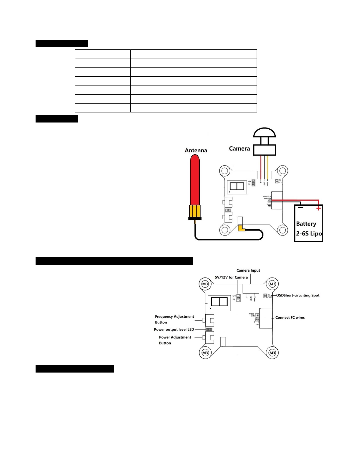
02Installation
1) Use the 3pin connecter wire( red black and yellow ) connect
the camera and VTx .(as the picture shown beside ) .
2) Connect the VTx“VCC” port to the battery “+” , and “GND” port
to the battery “-“(battery voltage must be 7-30V (2-6S Lipo)) .
3) The module leaves the factory with the antenna permanently
attached/glued.
4) Antenna manufacturer: HOBBYWING TECHNOLOGY Co.,
LTD.
Antenna brand: not applicable
Antenna model name:5.8GHz antenna ;
Antenna gain:2.5dbi
03 Layout & Ports of the Video Transmitter ( VTx )
•Short circuit the two OSD soldering points when
using the VTX separately , anddo not short circuit
the two points when pairing the VTX with the
HobbywingF4 flight controller and XRotor Micro
45A 4-in-1 ESC .
• Short circuit the corresponding two soldering
points to select the supplyvoltage of 5V/12V. If
short circuit the upper two points, then the VTX
willprovide the voltage of 12V to the camera; if
short circuit the lower two points,then the VTX will
provide the voltage of 5V to the camera.
04Parameter Adjustment
Frequency Point Adjustment (Frequency Set-Channel forms Frequency Point)
1)Display:If the LED segment display on the VTX displays “A2”, then it means the corresponding frequency is 5845MHz (as shown
in the form below).
2)Frequency Set Adjustment: press the “Frequency Adjustment Button” for 2 seconds to enter the frequency adjusting mode, and
the LED segment display starts to f lash; press the same button to change the frequency, the frequencies are circularly displayed
(from A to F); and press the same button for 2 seconds to save the setting and exit the mode after selecting the corresponding
frequency.
Channel Adjustment: press the “Frequency Adjustment Button” for 2 seconds to enter the channel adjusting mode, and the LED
Page 2

segment display starts to flash; press the same button to change the channel, the channels are circularly displayed (from 1 to 8); and
press the same button for 2 seconds to save the setting and exit the mode after selecting the corresponding channel.that’s to adjust
the channel after adjusting the frequency or adjust the frequency after adjusting the channel
3) Frequency Point -Frequency Table:
Channel
Frequency
1 2 3 4 5 6 7 8
A 5845MHz 5825MHz 5805MHz 5785MHz 5765MHz 5745MHz
B 5733MHz 5752MHz 5771MHz 5790MHz 5809MHz 5828MHz 5847MHz
F 5740MHz 5760MHz 5780MHz 5800MHz 5820MHz 5840MHz
R 5732MHz 5769MHz 5806MHz 5843MHz
press the “Frequency Adjustment
Button” for 2 seconds , then come into the
Frequency set
press the same button to
change the frequency
press the same button for 2
seconds to save the setting
and exit the mode
press the “Frequency
Adjustment Button” for 2
seconds to enter the channel
adjusting mode
Press the same button to
change the channel
press the same button for 2
seconds to save the setting and
exit the mode
Page 3

Federal Communication Commission Statement (FCC, U.S.)
This equipment has been tested and found to comply with the limits for a Class B digital device, pursuant
to Part 15 of the FCC Rules. These limits are designed to provide reasonable protection against harmful
interference in a residential installation. This equipment generates, uses and can radiate radio frequency
energy and, if not installed and used in accordance with the instructions, may cause harmful interference
to radio communications. However, there is no guarantee that interference will not occur in a particular
installation. If this equipment does
cause harmful interference to radio or television reception, which can be determined by turning the
equipment off and on, the user is encouraged to try to correct the interference by one of the following
measures:
- Reorient or relocate the receiving antenna.
- Increase the separation between the equipment and receiver.
- Connect the equipment into an outlet on a circuit different from that to which the receiver is connected.
- Consult the dealer or an experienced radio/TV technician for help.
This device complies with Part 15 of the FCC Rules. Operation is subject to the following two conditions:
(1) This device may not cause harmful interference, and (2) this device must accept any interference
received, including interference that may cause undesired operation.
FCC Caution:
Any changes or modifications not expressly approved by the party responsible for compliance could void
the user's authority to operate this equipment.
IMPORTANT NOTES
OEM integration instructions:
This module is intended only for OEM integrators under the following conditions:
This module is for professional installation only.
This module must be restricted to battery powered host devices only.
This module may not be co-located with any other transmitter or antenna.
This module shall only be used with the external antenna(s) as originally tested and certified with this module.
The OEM integrator is still responsible for testing their end-product for any additional compliance requirements for this module when installed, for example the 15C parameters of the RF module inside final host
shall be evaluated and confirm that the module´s intentional emissions are compliant (fundamental/out of band
band), whearea also the 15B digital device emissions shall be tested with the module installed and operating.
Validity of using the module certification:
In the event that these conditions cannot be met, then the FCC authorization for this module in
combination with the host equipment is no longer considered valid and the FCC ID of the module cannot
be used on the final product. In these circumstances, the OEM integrator will be responsible for reevaluating the end product (including the transmitter) and obtaining a separate FCC authorization.
End product labeling:
The final end product must be labeled in a visible area with the following:
“Contains FCC ID: 2AIWP-VTX5G8”.
 Loading...