

Page 1
Notice
d’utilisatioN
• This is not a toy! Not suitable for children under 14 years old without adult supervision.
• Ceci n’est pas un jouet. Ne convient pas aux enfants de moins de 14 ans sans la surveillance d’un adulte.
• Kein S pielzeug. Nichte geeignet für Kinder unter 14 Jahren ohne Aufsicht Erwachsener.
Page 2

ENGLISHfraN
ç
a ISDEUTSCH
3
WARRANTY AND SERVICE INFORMATIONS
COMPONENT WARRANTY PERIOD
PlEASE READ ThE FOllOWINg INFORMATION CAREFullY !
Please note this is a high-quality hobby product and not a toy. Therefore, it is necessary that children under 14 years are
supervised by an adult. The guardians and / or parents have the responsibility to provide the appropriate guidance and
supervision of the minors .
This product has a 90 day warranty, which is only guaranteed to the original purchaser. The warranty valid only to products
that have been purchased from an authorized Hobbytech dealer. Warranty claims will be processed only with a valid proof of
purchase / receipts. If within the warranty period, a portion of the product fails due to manufacturing defects, then it is within
the discretion of Hobbytech to repair it or replace it. The decision to repair or replace the part will be taken by Hobbytech. After
use, we do not oer new for old warranty.
WARRANTY DISCLAIMER
This high performance model was made with highest attention and care and should be treated with respect. Excluded from
the warranty are components that have been damaged by wrong installation, mishandling, accident, operation, maintenance,
lack of maintenance and care, as well as abuse and / or repair attempts. Furthermore excluded from the guarantee are wearing
parts such as fuses and batteries, visual impairments, shipping -, transport costs.
WARRANTY CLAIM
Please contact your dealer with the warranty claim and / or repair. Your dealer and Hobbytech will make an proper decision
that will help you as soon as possible. For invalid warranty claims you may be charged for the processing costs before the parts
are returned. All repairs which are necessary by negligence or abuse are bill in advance. In case you decide that you not want
to repair your product then Hobbytech editing and reserves the right to charge shipping costs .
Declaration of conformity in accorDance with the raDio &
telecommunications terminal equipment (r&tte) Directive 1999/5ec.
Sarl Imodel
5 place de Rome
13006 Marseille
France
Declares that he following product :
REVOLT BX10 3.0 RTR
w/ WAVE XT200/XR200 (KTH-90900-02G)
Item Number: XT WAVE-SET-WP
Equipment class: 1
Complies with the essential requirements and other relevant provisions
of the FTEG (Article 3 of the R&TTE directive)
• Protection of health and safety of the user and any other person,
(article 3.1a of the Directive)
Standards applied: EN 62311:2008
• The essential requirements of the Electromagnetic Compatibility
Directive (article 3.1b)
Standards applied: EN 301 489-1 V1.9.2 (2011-09)
EN 301 489-3 V1.4.1 (2002-08)
• Eective use of the radio spectrum/orbital resource so as to avoid
harmful interference (article 3.2).
Standards applied: EN 300 440-1 V1.6.1 (2010-08)
EN 300 440-1 V1.4.1 (2010-08)
Manufacturer Adress: Sarl Imodel
5 place de Rome
13006 Marseille
France
Date of issue: September 27, 2012
This product must not be disposed of with other
waste. Instead, it is the user’s responsibility to
dispose of their waste equipment by handing
it over to a designated collection point for the
recycling of waste electrical and electronic
equipment. The separate collection and
recycling of your waste equipment at the time of
disposal will help to conserve natural ressources
and ensure that it is recycled in a manner that
protects human health and the environment.
Help us to protect the environment and respect
our ressources !
i.A.
2
Page 3

ENGLISHfraN
ç
a ISDEUTSCH
3
WARRANTY AND SERVICE INFORMATIONS
COMPONENT WARRANTY PERIOD
PlEASE READ ThE FOllOWINg INFORMATION CAREFullY !
Please note this is a high-quality hobby product and not a toy. Therefore, it is necessary that children under 14 years are
supervised by an adult. The guardians and / or parents have the responsibility to provide the appropriate guidance and
supervision of the minors .
This product has a 90 day warranty, which is only guaranteed to the original purchaser. The warranty valid only to products
that have been purchased from an authorized Hobbytech dealer. Warranty claims will be processed only with a valid proof of
purchase / receipts. If within the warranty period, a portion of the product fails due to manufacturing defects, then it is within
the discretion of Hobbytech to repair it or replace it. The decision to repair or replace the part will be taken by Hobbytech. After
use, we do not oer new for old warranty.
WARRANTY DISCLAIMER
This high performance model was made with highest attention and care and should be treated with respect. Excluded from
the warranty are components that have been damaged by wrong installation, mishandling, accident, operation, maintenance,
lack of maintenance and care, as well as abuse and / or repair attempts. Furthermore excluded from the guarantee are wearing
parts such as fuses and batteries, visual impairments, shipping -, transport costs.
WARRANTY CLAIM
Please contact your dealer with the warranty claim and / or repair. Your dealer and Hobbytech will make an proper decision
that will help you as soon as possible. For invalid warranty claims you may be charged for the processing costs before the parts
are returned. All repairs which are necessary by negligence or abuse are bill in advance. In case you decide that you not want
to repair your product then Hobbytech editing and reserves the right to charge shipping costs .
Declaration of conformity in accorDance with the raDio &
telecommunications terminal equipment (r&tte) Directive 1999/5ec.
Sarl Imodel
5 place de Rome
13006 Marseille
France
Declares that he following product :
REVOLT BX10 3.0 RTR
w/ WAVE XT200/XR200 (KTH-90900-02G)
Item Number: XT WAVE-SET-WP
Equipment class: 1
Complies with the essential requirements and other relevant provisions
of the FTEG (Article 3 of the R&TTE directive)
• Protection of health and safety of the user and any other person,
(article 3.1a of the Directive)
Standards applied: EN 62311:2008
• The essential requirements of the Electromagnetic Compatibility
Directive (article 3.1b)
Standards applied: EN 301 489-1 V1.9.2 (2011-09)
EN 301 489-3 V1.4.1 (2002-08)
• Eective use of the radio spectrum/orbital resource so as to avoid
harmful interference (article 3.2).
Standards applied: EN 300 440-1 V1.6.1 (2010-08)
EN 300 440-1 V1.4.1 (2010-08)
Manufacturer Adress: Sarl Imodel
5 place de Rome
13006 Marseille
France
Date of issue: September 27, 2012
This product must not be disposed of with other
waste. Instead, it is the user’s responsibility to
dispose of their waste equipment by handing
it over to a designated collection point for the
recycling of waste electrical and electronic
equipment. The separate collection and
recycling of your waste equipment at the time of
disposal will help to conserve natural ressources
and ensure that it is recycled in a manner that
protects human health and the environment.
Help us to protect the environment and respect
our ressources !
i.A.
3
ENGLISHfraN
ç
aISDEUTSCHESpaÑoL
Page 4

ENGLISHfraN
ç
a ISDEUTSCH
4
IMPORTANT - READ ThIS BEFORE RuNNINg
PlEASE READ All INSTRuCTIONS AND FAMIlIARIzE YOuRSElF WITh ThE PRODuCTS AND CONTROl BEFORE
OPERATION.
This product is not a toy. It is a high performance model product. It is important to familiarize yourself with the model, its
manual, and its construction before assembly and operation. Adult supervision is necessary
CAUTION
To avoid serious personal injury and property damage, operate all remotely controlled models in a responsive manner as outlined below.
R/C car models can exceed speeds of 40km/h (25mph), and cannot be stopped quickly.
❶ Never run R/C models on the street or highways, as it could cause or contribute to serious trac accidents.
❷ Never run an R/C model near people or animals, nor use people or animals as obstacles when operation R/C vehicles.
❸ To avoid injury to persons or animals, and damage to property, never run a R/C model in a confined or crowed area.
❹ Running R/C models into furniture or other inanimate objects will cause damage to the objects and the R/C models.
CAUTION DURING OPERATIONS
When the R/C model is in operation, dot not touch any of its moving parts, such as drive shafts, wheels, as the rotating parts
can cause serious injury.
❶ The vehicle motor gets very hot during running and could cause burns if touched.
❷ Make sure that no one else is using the same frequency as yours in your running area. Using the same frequency at the same
time, whether is driving, flying or sailing, can cause loss of control of the R/C models, resulting in serious accidents.
❸ Properly connect plugs. To prevent electrical shock and/or damage to the product resulting from a short-circuit; insulate
connections with heat shrink tubing or electrical tape. Before running vehicle, check that battery wiring and plugs are not so
loose as to drag on the ground. Properly secure cables using electrical tape or nylon tie-wraps.
❹ Sti rotation of gears, shafts, joints and wheels can burn out the motor. It’s recommended to check proper joint and shaft
rotation by using one 1,5V dry cell during assembly of the model.
A worn motor will overheat and result in a short running time. Replace a worn out motor as soon as possible.
❺ R/C models will run out of control when either the receiver or transmitter battery voltage drops o. Stop the vehicle
immediately when the car starts to show down to prevent it from running out of control.
SAFETY PRECAUTIONS
Follow the outlined rules for safe radio control operation.
Avoid running the car in crowed area and near small children.
Make sure that no one else is using the same frequency in your running area. Using the same frequency at the same time can
cause serious accidents, whether it’s driving, flying or sailing.
Avoid running in standing water and rain. If R/C unit, motor, or battery get wet, clean and dry throughly in a dry shaded area.
R/C operating procedures
❶ Make sure the transmitter controls and trims are in neutral. Switch on transmitter.
❷ Switch on receiver.
❸ Inspect operation using transmitter before running.
❹ Adjust steering servo and trim so that the model runs straight with transmitter in neutral.
❺ Reverse sequence to shut down after running.
❻ Make sure to disconnect/remove all batteries.
❼ Completely remove sand, mud, dirt etc
❽ Store the car and batteries separately when not in use
SETTING UP THE MODEL
To greatly enhance the overall performance of your car, it’s necessary to tune the vehicle to the track (and its surface
conditions) on which you will be racing. Make adjustments referring to the instruction manual, keeping in mind that “balance” is
the key word.
❶ Tires
Tires have a great influence on the performance of your car, and are normally the first components tuned. Select the right tires
for the track you are racing on.
❷ Toe-in and Toe-out
Adjusting the car toe-in a little, by pointing the wheel inwards, provides the car with good straight running and moderate
steering characteristics. Toe-out, which point the wheels outwards, gives sharp and crisp steering. Take care not to overdo.
❸ Camber angle
While taking the corners, the car is forced to go outwards, causing instability. The area of contact on each tire is determined
by the camber angle, and therefore the traction of the tires can be made greater or lesser by adjustment of camber angle. To
increase traction during cornering, adjust camber angle negative, and reduce traction, adjust for positive camber.
❹ Ground clearance and suspension drop
Ground clearance and/or rebound stroke has a great eect on stability during cornering, acceleration, and braking. Ground
clearance can be adjusted by altering damper spring tension and stiness.
❺ Gear ratio
Proper gear ratio should be determined by the available output power of the motor; type of battery; track condition and layout
It should be also noted that running the car on a good grip surface suggests use of pinion gear 1 teeth smaller, in order to
eectively use all of the available battery power.
ENGLISHfraN
ç
a ISDEUTSCH
5
Curved lexan scissors
EX 421200
EX 421932
Nut driver 7mm
4xAA Alkaline batteries
TOOLS REQUIRED NOT INCLUDED IN THE KIT
Multifonction pliers complety set
Knife
cHassis
Receiver
Battery
Wing
Steering
servo
ESC
Motor
Rear tyre
Front tyre
Front
shock unit
Rear
shock unit
Chassis
HT 421910
1-10 scale full tool set
Hex wrench 1,5-2mm
Philips 1.5mm
Nut driver 5.5mm
4
ENGLISHfraN
ç
aISDEUTSCHESpaÑoL
Page 5

ENGLISHfraN
ç
a ISDEUTSCH
5
Curved lexan scissors
EX 421200
EX 421932
Nut driver 7mm
4xAA Alkaline batteries
TOOLS REQUIRED NOT INCLUDED IN THE KIT
Multifonction pliers complety set
Knife
cHassis
Receiver
Battery
Wing
Steering
servo
ESC
Motor
Rear tyre
Front tyre
Front
shock unit
Rear
shock unit
Chassis
HT 421910
1-10 scale full tool set
Hex wrench 1,5-2mm
Philips 1.5mm
Nut driver 5.5mm
5
ENGLISHfraN
ç
aISDEUTSCHESpaÑoL
Page 6

ENGLISHfraN
ç
a ISDEUTSCH
6
EVEN IF THIS CAR IS A READY TO RUN KIT, YOU STILL HAVE SOME LITTLE THINGS TO DO TO FAMILIARIzE WITH YOUR
PRODUCT.
PLEASE FOLLOW THESE STEPS.
Slide the antenna wire into the antenna pipe carefully. Fix the antenna pipe into its holder.
Tighten the small screw provided to secure the antenna tube.
WARNING!
Do not use the charger if wire is
frayed or worn.
Do not use the charger near
water or worm.
Connect the AC charger to
a wall 220V plug, the green
LED brights. Then connect the
battery, the LED becomes red :
battery is charging.
After a charging time of 2 hours,
the battery will be charged. (red
LED becomes green). Put the battery in its mount.
bodY and winG assEmblY
antEnna pipE & wirE assEmblY
cHarGinG tHE li-ion battErY install battErY on car
A
Remove the body clips.
B
Remove the body.
C
Remove the body mask before putting the stickers.
Put the stickers.
Fix the wing on the its mount with the o-ring and body clips
provided with the kit.
A B
C
6
ENGLISHfraN
ç
aISDEUTSCHESpaÑoL
Page 7
ENGLISHfraN
ç
a ISDEUTSCH
7
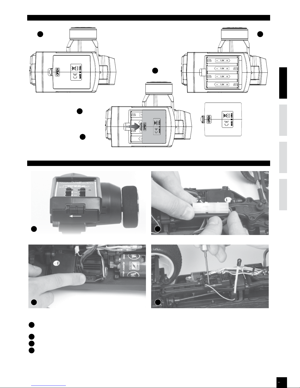
- Remove the battery cover from the
transmitter by sliding it in the direction
of the arrow in the figure
B
.
- Remove used batteries.
- Load new AA size batteries. Pay very
close attention to polarity markings
and reinsert accordingly (
C
).
- Slide the battery cover back onto
the case.
Place model on a block to prevent wheels from touching the ground.
A
Turn on transmitter switch and the LED battery indicator will light up. If it blinks or doesn’t light up, check polarities and battery power.
If the battery power is low, replace batteries with new ones.
B
Connect battery to ESC. Fix the wire correctly with the provided connectors.
C
Turn ON receiver switch.
D
You must check the signal of transmitter and receiver before you operating it at first.
Make sure TH Trim is on neutral, TH D/R is on maximum value (10), and ST in on NOR.
- With a tip, push on SWITCH receiver button during 3 seconds, then release : Red LED blinks, then lights. This means your
transmitter is correctly synchronized with your receiver.
install battEriEs on transmittEr
bind
A
B
C
A B
C D
7
ENGLISHfraN
ç
aISDEUTSCHESpaÑoL
Page 8
ENGLISHfraN
ç
a ISDEUTSCH
8
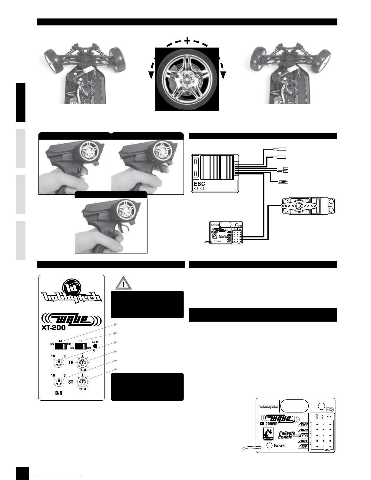
If the wheels operate in the opposite direction, operate the servo reverse switch (ST in position NOR).
Throttle Trim is used to accurately adjust the Forward /
Backward neutral.
Steering Trim is used to slightly trim the front wheels steering.
Note: If the front wheels are not straight when the trigger is
set at Neutral position, you can adjust the steering.
Steering Trim
Steering Dual/Rate
Steering Servo Reverse
Throttle Trim
Throttle Dual/Rate
Throttle Servo Reverse
Notice : please keep the
transmitter and receiver from
over 40cm distance away,
when you operate the unit.
low battErY alarmtransmittEr adjustmEnt
If the transmitter battery voltage drops below 4.5V an alarm will
sound and LOW BT will be displayed on the LCD screen. The low
battery alarm is meant to be a safety feature only. Do NOT operate
your radio below 9V. Always shut your radio o as soon as possible
after the low battery warning tone to avoid loss of control.
tHE sEttinG oF rEcEivEr
witH Fail saFE pErFormancE
1. Please press the TH, ST switch of transmitter to the normal
control position. Turn on the transmitter and turn on the
receiver at the same time, the LED on the receiver will be
bright all the time.
2. The LED on the receiver becomes fast flashing if you press
the F/S SET.
3. Put the transmitter’s throttle wheel to the brake degree
which you want, press the F/S SET on the receiver, the red
LED will be bright all the time, then the setting is over.
4. Please put the throttle
wheel on the neutral
position when you use
it on the electric car.
5. The vehicle will
stay on neutral
(no speeding up,
no braking) when
you close the
transmitter.
I f you are a reverse
operator, set the steering
and / or throttle switch to
REV. Position first.
rEcEivEr and sErvo connEction
ESC
Receiver
CH1
Steering Servo
Power Switch
Connect to
battery
Connect to motor
CH2
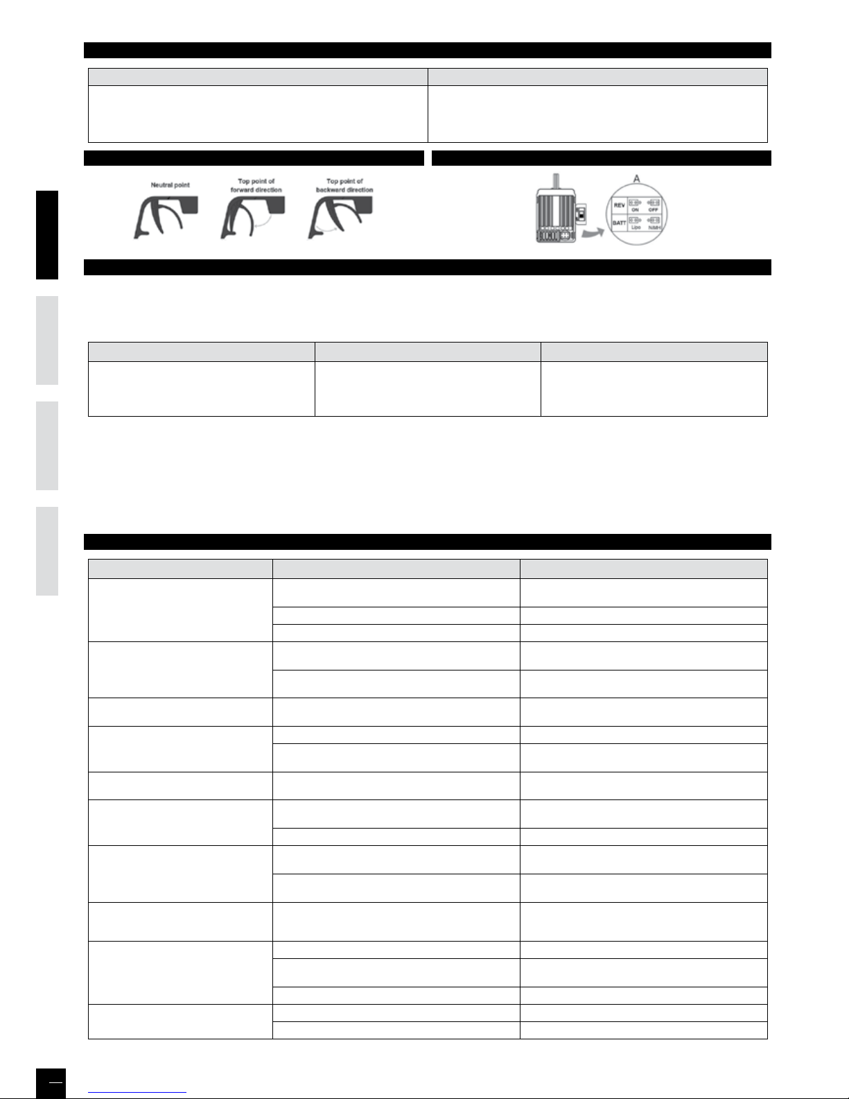
nEutral position
Forward / spEEd up position
brakE / spEEd down position
How to control Your modEl
nEutral
lEFt riGHt
8
ENGLISHfraN
ç
aISDEUTSCHESpaÑoL
Page 9

ENGLISHfraN
ç
a ISDEUTSCH
9
High power system for RC model can be very dangerous, so we strongly suggest you read this manual carefully. In that
hobbytech have no control over the correct use, installation, application, or maintenance of our products, no liability shall be
assumed nor accepted for any damages, losses or costs resulting from the use of the product.
ANY CLAIMS ARISING FROM THE OPERATING, FAILURE OF MALFUNCTIONING ETC. WILL BE DENIED. WE ASSUME NO LIABILITY FOR
PERSONAL INJURY, CONSEQUENTIAL DAMAGES RESULTING FROM OUR PRODUCT OR OUR WORKMANSHIP. AS FAR AS IS LEGALLY
PERMITTED, THE OBLIGATION TO COMPENSATION IS LIMITED TO THE INVOICE AMOUNT OF THE AFFECTED PRODUCT.
FEaturEs
1. Water-proof and dust-proof for all weather races.
2. Small size with built-in capacitor module.
3. Automatic throttle range calibration, easy to use.
4. Multiple protections: Low voltage cut-o protection for Lipo or NiMH battery / Over-heat protection / Throttle signal loss
protection.
5. Easily programmed with the jumpers.
spEciFications
Model XT BRUSH10WP/HW
Cont. / Burst Current
Forward: 40A / 180A
Backward: 20A / 90A
Input 2-3S Lipo, 5-9 Cells NiMH/NiCd
Cars Applicable
1:10 on-road, o-road Buggy, Truggy, SCT
1:10 Crawler, Tank & Boat
Motor
Limit
2 Lipo
or 5-6 NiMH
540 or 550 size motor ≥12T
RPM < 30000 @7.2V
3 Lipo
or 7-9 NiMH
540 or 550 size motor ≥18T
RPM < 20000 @7.2V
Resistance
FWD: 0.002 Ohm
BWD: 0.004 Ohm
Built-in BEC 2A/5V (Linear mode BEC)
PWM Frequency 1KHz
Dimension & Weight 46.5*34*28.5, 65g
bEGin to usE
1. Connect the ESC, motor, receiver, battery and servo according to the following diagram
“+” and “-” wires of the ESC are connected to the battery
pack.
ATTENTION: The incorrect polarity will damage the ESC
immediately.
The control cable of the ESC (trio wires with black, red
and white color) is connected to the throttle channel of
the receiver (Usually CH2).
The “Motor +” and “Motor –” wires are connected to
ESC without any order. If the motor runs in the opposite
direction, please swap these two wire connections.
2. Set the Transmitter
Please set the “D/R”, “EPA” and “ATL” to 100% for throttle
channel (for transmitter without LCD, please turn the
knobs to the maximum value), and set the “TRIM” of the
throttle channel to 0 (for transmitter without LCD, please
turn the TRIM knob to its neutral position).
For FutabaTM and the similar transmitters, the direction of throttle channel shall be set to “REV”, while other radio systems shall
be set to “NOR”.
The “Fail Save” function of the radio system is strongly recommended to be activated. Please make sure that the motor can be
stopped when the “Fail Save” happens.
3. Throttle Range Setting (Throttle Range Calibration)
In order to make the ESC match the throttle range of dierent transmitters, the calibration of the ESC is necessary.
To calibrate the ESC, please turn on the transmitter, keep throttle stick at its neutral position, wait for 3 seconds to let the ESC
execute self-test and automatic throttle calibration. When the ESC is ready to run, a long beep sound is emitted from the
motor.
Note: Please calibrate the throttle range again when using a new transmitter or changing the settings of the neutral position of
throttle channel, D/R, ATV, ATL or EPA parameters, otherwise the ESC may not work properly.
40amp brusHEd watErprooF Esc - instruction manual
9
ENGLISHfraN
ç
aISDEUTSCHESpaÑoL
Page 10
ENGLISHfraN
ç
a ISDEUTSCH
10
bEEp sound and lEd status
The Meaning of Beep Sound LED Status
∞ 1 short Beep: The battery is NiMH/NiCd
∞ 2 short Beeps: The battery is 2S Lipo
∞ 3 short Beeps: The battery is 3S Lipo
∞ 1 long Beep: Self-test and throttle calibration is OK, the ESC is ready to run
∞ When the throttle stick is in neutral range, red LED is o
∞ Forward, brake or reverse at partial throttle, red LED blinks
∞ Forward, brake or reverse at full throttle, red LED is solid
tHrottlE sEt tHE Esc
protEction Functions
1. L O W VOLTAGE CUTOFF PROTECTION: If the voltage of battery pack is lower than the threshold for 2 seconds, the ESC will
enter the protection mode.
When the car stops, the red LED blinks to indicate the low voltage cut-o protection has been activated.
2S Lipo 3S Lipo 5-9 cells NiMH
Output reduces 50% at 6.5V
Output cuts o at 6.0V, cannot be
recovered
Output reduces 50% at 9.75V
Output cuts o at 9.0V, cannot be
recovered
Output reduces 50% at 4.5V
Output cuts o at 4.0V, cannot be
recovered
2. OVERHEAT PROTECTION: When the internal temperature of the ESC is higher than a factory preset threshold for 5
seconds, the ESC will reduce and cut o the output power.
When the car stops, the red LED blinks to indicate the over-heat protection has been activated. If the ESC cools down to 80
Celsius degree, the output power is recovered to normal state.
3. THROTTLE SIGNAL LOSS PROTECTION: The ESC will cut o the output power if the throttle signal has been lost for 0.1
second. The “Fail Save” function of the radio system is strongly recommended to be activated.
troublE sHootinG
TROUBLE POSSIBLE REASON SOLUTION
After power on, motor can’t work, no
sound is emitted, and LED is o
The ESC doesn’t get its working voltage; Connections
between battery pack and ESC are broken
Check the battery wires connection or replace the
defective connectors
Switch is damaged Replace the switch
Polarity or battery type is wrong Check polarity and battery type
After power on, motor can’t work; red
LED blinks
Throttle signal is abnormal
Check the throttle wire connection; make sure it is
plugged into the throttle channel of the receiver
Automatic throttle range calibration is failed
Set the “TRIM” of throttle channel to 0 or turn the knob
to its neutral position
The motor runs in the opposite direction
The wire connections between ESC and the motor need
to be changed
Swap two wire connections between the ESC and the
motor
The car can’t go backward
The jumper position is wrong Check the jumper and plug it to the correct position
The neutral point of throttle channel is changed or
drifted
Set the “TRIM” of throttle channel to 0 or turn the knob
to its neutral position
The car can’t go forward, but can go
backward
The direction of throttle channel is not correct
Reset the direction of throttle channel from original
“NOR” to “REV”, or from original “REV” to “NOR”
The motor doesn’t work, but the LED in
the ESC works normally
The connections between motor and ESC are broken
Check the connections and replace the defective
connectors
Motor is damaged Replace the motor
The motor suddenly stops running while
in working state
The throttle signal is lost
Check the transmitter and the receiver.
Check the throttle wire connection
Low voltage cut-o protection or Over-heat cut-o
protection has been activated
Replace the battery pack, or cool down the ESC
The car cannot get top speed and the red
LED doesn’t solid on at full throttle
Some setting in the transmitter are incorrect
Set D/R, EPA, ATL to 100% or turn the knobs to
maximum value.
Set TRIM to 0 or turn the knob to its neutral position
Motor is cogging when accelerated
quickly
The battery has limited discharge ability Use battery with better discharge ability
Motor RPM is too high, the gear ratio is too aggressive
Use motor with lower RPM, or use smaller pinion to get
softer gear ratio
Something wrong in the driving system of the car Check the driving system of the car
The car doesn’t run straight
Steering TRIM is not adjusted correctly Make adjustment of the TRIM
Wheel nuts are too loose Tighten wheel nuts
10
ENGLISHfraN
ç
aISDEUTSCHESpaÑoL
Page 11

ENGLISHfraN
ç
aISDEUTSCH ENGLISHfraNçaISESpaÑoL DEUTSCH
11
GARANTIE DE 90 JOURS
MERCI DE LIRE ATTENTIVEMENT LES LIGNES CIDESSOUS :
A partir de la date d’achat, le produit est couvert par une garantie de 90 jours couvrant les composants. Si durant cette période,
une des pièces composantes votre produit (hormis les pièces de transmission) possède un défaut de fabrication réellement
constaté par notre service technique, la pièce sera réparée ou échangée. Une fois cette nouvelle pièce utilisée, elle ne sera plus
garantie.
Il est important de savoir que ce produite est en aucun cas un jouet, il est recommandé aux moins de 14 ans uniquement
sous la surveillance d’un adulte. Il est de la responsabilité des parents ou du tuteur de garantir que les moins de 14 ans ont une
supervision nécessaire.
Lors de l’utilisation, si vous vous apercevez qu’il existe un problème avec le produit, il est de la responsabilité de l’acquéreur de
rechercher et de corriger le problème avant de causer des dommages plus importants.
NON GARANTIE
Ce produit est un modèle de haute performance et sophistiqué, il sera dans tous les cas traité avec soins et respect. Au niveau
conception et choix des matières, tout a été fait pour vous apporter un produit endurant et robuste. Toutefois, lors d’utilisation
sévère et anormale, il est possible de casser et d’endommager les pièces composantes le modèle.
La garantie ne couvre pas l’usure normale d’un produit ni la casse résultant de son utilisation .Elle ne s’applique pas non plus à
la réparation de dommages résultant d’une cause externe à l’appareil (par exemple d’un accident, d’un choc, de la foudre, de
la tempête, de la présence d’eau, (et plus généralement tous corps étrangers à l’appareil, d’une fluctuation de courant, d’une
oxydation…), d’une installation ou d’un branchement non conformes aux spécifications ou prescriptions du constructeur,
d’une utilisation nuisible à la bonne conservation de l’appareil, d’une utilisation à caractère professionnel, de l’utilisation de
périphériques, d’accessoires ou de consommables inadaptés, ou encore aux appareils démontés ou modifiés.
MISE EN PLACE DE LA GARANTIE
Dans un premier temps, veuillez retourner le produit chez votre revendeur, en tant que professionnel il vous conseillera sur la
possibilité ou pas de la prise en garantie.
Surtout, n’envoyez pas le produit directement chez le distributeur avant d’avoir vu votre revendeur et/ou sans l’accord du
distributeur.
Vous n’avez pas à envoyer le produit en entier, seulement l’élément défectueux avec le formulaire qui vous sera transmis en
amont. Dans tous les cas, ces frais d’expédition sont à votre charge. Dans beaucoup de cas, il est plus rapide et rentable pour
l’utilisateur de remplacer directement la pièce.
Attention, toute pièces retournées et inspectées par le service technique du distributeur qui ne s’avère pas prise en garantie,
peut être sujette à des frais d’inspection, de manipulation et de retour à votre charge. Si le produit défectueux demande une
réparation et ne rentre pas dans les conditions couvertes par la garantie, ces réparations vous seront facturées au prix horaire
en cours applicable par le service technique du distributeur.
Si vous décidez de ne réaliser aucun travail de réparation, le distributeur se réserve le droit de facturer les frais d’inspection, de
manipulation et d’expédition.
Nous vous conseillons de garder précieusement votre preuve d’achat, elle pourrait vous être utile.
DÉCLARATION DE CONFORMITÉ SELON LA DIRECTIVE R&TTE 1999/05/CE
Sarl Imodel
5 place de Rome
13006 Marseille
France
Declare que le produit suivant : REVOLT BX10 3.0 RTR
w/ WAVE XT200/XR200 (KTH-90900-02G)
Item Number : XT WAVE-SET-WP
Catégorie d’équipement : 1
Correspond aux exigencies essenttieles de la directive FTEG (Article 3 de la directive
R&TTE)
• Protection de la santé et de la sécurité de l’utilisateur et de toute autre personne
conformément à l’article 3.1.a
Norme appliqué : EN 62311:2008
• Exigence en matière de protection en rapport à la compatibilité électromagnétique
(article 3.1b)
Normes appliquées : EN 301 489-1 V1.9.2 (2011-09)
EN 301 489-3 V1.4.1 (2002-08)
• Utilisation ecace du spectre attribué aux communications radio terrestres ou spatiales
ainsi que les ressources orbitales pour éviter les interférences dommageables (article 3.2).
Normes appliquées: EN 300 440-1 V1.6.1 (2010-08)
EN 300 440-1 V1.4.1 (2010-08)
Adresse du fabricant : Sarl Imodel
5 place de Rome
13006 Marseille
France
Date de délivrance : 27 septembre 2012
Ce pictogramme indique que le produit ne doit pas être traité
comme déchet ménager. Vous devez veiller à éliminer ce produit
correctement afin d’éviter toute atteinte à l’environnement
et à la santé humaine. Un traitement ou une mise au rebut
inappropriés de ce produit pourraient avoir des conséquences
négatives sur l’environnement et la santé humaine. Aidez-nous
à respecter l’environnement !
i.A.
Page 12

ENGLISHfraN
ç
aISDEUTSCH ENGLISHfraNçaISESpaÑoL DEUTSCH
12
IMPORTANT LIRE AVANT DE DÉMARRER
LIRE CES INSTRUCTIONS ET SE FAMILIARISER AVEC LE PRODUIT AVANT DE S’EN SERVIR.
Ce produit n’est pas un jouet. C’est un modèle réduit de haute performance. Il est important de se familiariser avec le modèle,
son manuel et sa construction avant l’assemblage et le fonctionnement. La surveillance d’un adulte est nécessaire.
ATTENTION
Afin d’éviter tout dommage à des personnes ou à des biens, utiliser le modèle radio-commandé de manière responsable
comme décrit ci-après. Les modèles radio commandés peuvent atteindre des vitesses supérieures à 40km/h (25mph) et ne
peuvent s’arrêter instantanément.
❶ Ne jamais conduire le modèle radio-commandé sur les routes et dans les rues car il pourrait provoquer des accidents qui
causeraient de graves dommages.
❷ Ne pas rouler près de personnes ou d’animaux. Ne pas utiliser les personnes ou animaux comme obstacles.
❸ Pour éviter tout dommage aux personnes et animaux, ne pas conduire dans un endroit bruyant ou trop exigu.
❹ Piloter le modèle radio-commandé à l’intérieur entre des objets statiques peut causer des dommages aux objets et au
modèle radio-commandé.
PRÉCAUTIONS À OBSERVER PENDANT L’UTILISATION
Lorsque le modèle R/C est en marche, ne jamais toucher les parties en mouvement (transmission, roues, engrenages…)
❶ Quand le modèle roule, son moteur fonctionne continuellement et il chaue. Il peut atteindre une température élevée.
Ne pas le toucher, risque de brûlures. Faire Attention !
❷ S’assurer que personne n’utilise la même fréquence. Si c’est le cas, le contrôle du modèle risque d’être perdu et causer des
accidents.
❸ Préserver tous les fils des frottements et des pièces en rotation. Veiller à ce que les connecteurs soient bien enfichés et les
sécuriser avec la gaine thermorétractable ou de la bande adhésive d’isolation. Fixer les câbles au châssis avec des colliers en
nylon. Réparer immédiatement les fils et les connexions endommagés.
❹ Le moteur risque d’être endommagé si toutes les pièces en mouvement ne tournent pas librement : roues, axes de
transmission, pignonnerie…Le moteur risque de chauer plus que la normale, il consommera plus d’énergie et diminuera
l’autonomie de l’accu. Il est important de vérifier régulièrement que toutes ces pièces et le moteur sont en bon état.
Dans le cas contraire, les changer immédiatement.
❺ Si l’accu devient trop faible pour alimenter le récepteur, le contrôle du modèle est perdu. Arrêter le modèle quand il
commence à ralentir pour éviter de perdre le contrôle.
CONSIGNES DE SÉCURITÉ
- Ne pas faire fonctionner le modèle au milieu d’enfants ou de la foule.
- Vérifier que personne d’autre n’utilise la même fréquence dans le même secteur car cela pourrait provoquer de sérieux incidents.
- Ne pas rouler dans l’eau ou sous la pluie. Si le moteur, le dispositif électrique ou l’accumulateur est mouillé, le sécher immédiatement.
Ordre de fonctionnement fondamental du modèle sans fil:
❶ Allumer l’émetteur après avoir mis le trim de gaz à la position neutre.
❷ Brancher le contact du récepteur.
❸ Avant de faire fonctionner, s’assurer du bon fonctionnement des 2 voies de votre émetteur.
❹ Régler le trim du volant, agir sur le curseur pour que le modèle puisse avancer droit.
❺ Après avoir arrêté de conduire, arrêter le récepteur et ensuite la radiocommande.
❻ Débrancher tous les accumulateurs.
❼ A la fin de chaque fonctionnement, nettoyer l’ensemble du modèle.
RÉGLAGES
Pour augmenter les performances du modèle, il est nécessaire de le régler en fonction de la surface et du tracé du circuit sur lequel il
roulera. Faire les réglages en se référant aux instructions de ce manuel.
Garder à l’esprit que « l’équilibre » est le maître mot.
❶ Pneus - Le pneu a une grande influence sur les performances de la voiture et sont normalement les premiers composants qu’il faut
modifier en fonction du circuit. Sélectionner les bons pneus pour le circuit où le modèle roulera en fonction de la surface et/ou des
conditions atmosphériques.
❷ Pincement et ouverture - Régler le modèle avec un peu de pincement procure un meilleur maintien du cap en ligne droite mais
diminue le rayon de braquage. L’ouverture procure une direction plus marquée et plus incisive, elle permet de tourner plus court.
Exagérer les modifications réduira les facultés du modèle.
❸ Carrossage positif & négatif - Lorsque le modèle tourne dans un virage, il subit la force centrifuge qui le pousse à l’extérieur du
virage, cela provoque une perte d’adhérence et de stabilité. La surface de contact de chaque pneu avec le sol est déterminée par l’angle
de carrossage. La traction des pneus peut être augmentée ou diminuée en modifiant le carrossage.
Pour augmenter l’adhérence dans les virages il faut augmenter le carrossage négatif. Pour réduire l’adhérence, augmenter le carrossage
positif.
❹ Garde au sol & débattement de la suspension - La garde au sol et le débattement des suspensions ont un eet direct sur la stabilité
en virage, accélération, freinage. La garde au sol peut être ajustée en modifiant la tension des ressorts des amortisseurs.
❺ Rapport de transmission - Le bon rapport de transmission est déterminé par la puissance du moteur + le type d’accu + les
conditions du circuit. Il est à noter que rouler sur un circuit avec une bonne adhérence suggère d’utiliser un pignon d’1 dent plus petite
afin d’utiliser toute la capacité de l’accu.
Page 13

châssis
Récepteur
Batterie
Aileron
Servo de
direction
Contrôleur
Moteur
Pneu arrière
Pneu avant
Amortisseur
avant
Amortisseur
arrière
Châssis
ENGLISHfraN
ç
aISDEUTSCH ENGLISHfraNçaISESpaÑoL DEUTSCH
13
Ciseaux a lexan courbes
EX 421200
4 piles Alkaline R6
outillage requis NoN iNclus daNs le kit
Gamme multifonction de pinces
Cutter
HT 421910
Gamme d’outils complète 1/10
Clé allen 1,5-2mm
Tournevis cruciforme 1.5mm
Clé à douille 5.5mm
EX 421932
Clé à douille 7mm
Page 14

ENGLISHfraN
ç
aISDEUTSCH ENGLISHfraNçaISESpaÑoL DEUTSCH
14
MÊME SI CE MODÈLE EST LIVRÉ PRÊTÀROULER, IL RESTE TOUT DE MÊME CERTAINES OPÉRATIONS À EFFECTUER, EN
PROFITER POUR SE FAMILIARISER AVEC VOTRE MODÈLE.
SUIVRE LES ÉTAPES PAS À PAS.
Glisser le fil d’antenne dans le tube avec précaution. Fixer le tube d’antenne sur son support.
Visser la petite vis fournie afin de bien fixer le tube d’antenne.
ATTENTION !
Ne pas utiliser ce chargeur si les
fils sont dénudés ou abimés.
Ne pas utiliser ce chargeur à
proximité d’un endroit humide
ou brûlant.
Connecter le chargeur 220V à
une prise murale, la LED verte
s’allume. Puis connecter la
batterie, la LED rouge s’allume :
la batterie est en charge.
Après un temps de charge
d’environ 2 heures, la batterie
sera chargée (la LED rouge
tourne au vert).
Installer la batterie dans son support.
assemblage de la carrosserie et de l’aileroN
FixatioN de l’aNteNNe
chargemeNt de la batterie li-ioN iNstallatioN de la batterie
A
Retirer les clips.
B
Retirer la carrosserie.
C
Enlever le masque de protection de la carrosserie avant
d’appliquer les autocollants.
Appliquer les autocollants.
Fixer l’aileron sur son support à l’aide des joints noirs et des
clips fournis dans le kit.
A B
C
Page 15

ENGLISHfraN
ç
aISDEUTSCH ENGLISHfraNçaISESpaÑoL DEUTSCH
15
- Ouvrir le couvercle inférieur comme
indiqué sur la figure
B
.
- Retirer les piles usagées s’il s’agit
d’un remplacement.
- Mettre en place les 4 nouvelles piles
de type R6 (AA), faire très attention
aux polarités marquées au fond du
boîtier (
C
).
- Remettre en place le couvercle
inférieur.
Poser le véhicule sur un bloc pour éviter que les roues ne touchent le sol.
A
Allumer l’émetteur et l’indicateur de batterie s’allume. S’il clignote ou ne s’allume pas, vérifier les polarités et l’alimentation des piles.
Si l’énergie des piles est faible, remplacer les piles par des neuves.
B
Brancher la batterie au contrôleur à l’aide des connecteurs. Vérifier que tous les composants câbles et électroniques sont
correctement installés.
C
Allumer le récepteur.
D
Il est impératif de contrôler la correcte synchronisation entre l’émetteur et le récepteur avant leur 1ère utilisation.
S’assurer que le Trim TH est au neutre, que D/R TH est à la valeur maxi (10) et que la voie ST est sur NOR.
- À l’aide d’une pointe, appuyer sur le bouton SWITCH du récepteur durant 3 secondes, puis relacher : la LED rouge
clignote puis reste fixe. Cela signifie que l’émetteur est correctement synchronisé avec votre récepteur.
iNstallatioN des batteries de l’émetteur
coNtrôle et appairage de la radio (biNd)
A
B
C
A B
C D
Page 16

ENGLISHfraN
ç
aISDEUTSCH ENGLISHfraNçaISESpaÑoL DEUTSCH
16
commeNt piloter votre véhicule
Neutre
gauche droite
Si les roues ne tournent pas dans le sens indiqué sur ce schéma, changer la position du bouton de l’inversion de servo (ST en
postion NOR).
Le trim gaz/frein est utilisé pour ajuster avec précision le
neutre Avant / Arrière.
Le trim de direction est utilisé pour ajuster précisément la
direction du véhicule.
Note : Si les roues du véhicule ne sont pas droites quand le
servo de direction est au neutre, vous devez ajuster avec le
trim de direction
Trim Direction
Dual/Rate Direction
Inversion Direction
Trim Gaz/frein
Dual/Rate Gaz/frein
Inversion Servo gaz/frein
Attention : placez votre
émetteur au minimum à
40cm du récepteur lors de
toutes les opérations.
alarme de décharge de la batterieréglages de la radio
Lorsque la tension d’alimentation de la batterie se trouve en
dessous de 4.5V, les diodes lumineuses «low» et «full» clignotent.
Dans ce cas, ne plus utiliser votre émetteur, il est impératif de
remplacer ou recharger les piles.
Pour éviter toute perte de contrôle lorsque le tension est trop
basse, il est impératif d’arrêter le plus rapidement possible
d’utiliser la radiocommande.
paramétrage des récepteurs
équipés de Fail saFe
1. Mettre en route l’émetteur et le récepteur, la LED du
récepteur s’allume en continue.
2. La LED du récepteur flashe en discontinue rapidement si
vous appuyez sur le bouton FAIL SAFE du récepteur.
3. Donner les positions de la gâchette, appuyer sur le bouton
FAIL SAFE du récepteur, la LED rouge s’allume en continue,
la position de sécurité est paramétrée.
4. Il est conseillé de
mettre la gâchette
en position neutre
pour les véhicules
électriques.
5. Le véhicule restera au
neutre (ni accélération,
ni freinage) quand
vous éteindrez
l’émetteur.
Si vous devez changer le
sens des servos, pensez à
inverser auparavant puis
régler les trims.
braNchemeNts récepteurs / servos
ESC
Récepteur
CH1
Servo de direction
Interrupteur
Connecter à la
Batterie
Connecter au Moteur
CH2
positioN Neutre
positioN accélératioN
positioN FreiN puis marche arrière
Page 17

ENGLISHfraN
ç
aISDEUTSCH ENGLISHfraNçaISESpaÑoL DEUTSCH
17
Ces variateurs haut de gamme spécifiques à la RC peuvent être très dangereux, nous recommandons de lire attentivement la
notice.
HobbytecH
ne possède aucun contrôle sur l’utilisation, l’installation ou la maintenance de ses produits et ne couvre pas
en garantie les dommages, les pertes et la mauvaise utilisation de celui-ci.
ATTENTION, TOUTE MODIFICATION DU PRODUIT (ex : SOUDURE, CHANGEMENT DE FILS, CHANGEMENT DU VENTILATEUR,
CHANGEMENT DE CONNECTEUR), ENTRAINERA UNE ANNULATION FERME ET IMMÉDIATE DE TOUTE PRISE EN CHARGE DE
NOTRE SERVICE APRÈS-VENTE.
caractéristiques
1. Ne craint ni les éclaboussures ni la poussière.
2. Petit encombrement pour une forte puissance.
3. Calibrage des courses de gaz automatique, facile d’utilisation.
4. Diérentes protections : coupure de protection basse tension pour les batteries LiPo et NiMH,
protection contre la surchaue, contre les pertes radio.
5. Facile à programmer avec les ponts.
spéciFicatioNs techNiques
Modèle XT BRUSH10WP/HW
Courant continu
Marche avant : 40A / 180A
Marche arrière : 20A / 90A
Voltage d’alimentation 2-3S Lipo, 5-9 cellules NiMH/NiCd
Type de voiture
1:10 on-road, o-road Buggy, Truggy, SCT
1:10 Crawler, Tank & Bateau
Limite du
moteur
2 Lipo
or 5-6 NiMH
540 or 550 ≥12T
RPM < 30000 @7.2V
3 Lipo
or 7-9 NiMH
Taille de moteur 540 ou 550 ≥18T
RPM < 20000 @7.2V
Résistance
Marche avant : 0.002 Ohm
Marche arrière : 0.004 Ohm
Entrée BEC 2A/5V (Mode linéaire BEC)
Fréquence PWM 1KHz
Dimensions, Poids 46.5*34*28.5, 65g
première utilisatioN du variateur
1. Brancher le variateur, le moteur, le récepteur, la batterie et le servo selon le schéma suivant :
Les fils “+” et “-” du variateur sont branchés au pack de
batterie.
ATTENTION : Une mauvaise polarité endommagera
immédiatement le variateur.
Le câble de contrôle du variateur (tricolore, noir, rouge
et blanc) est branché sur la voie des gaz du récepteur
(habituellement CH2).
Les câbles “Moteur +” and “Moteur –” sont branchés au
variateur sans ordre précis. Si le moteur tourne en sens
inverse, échanger les emplacements de ces 2 connexions.
2. Réglage de l’émetteur
Régler “D/R”, “EPA” and “ATL” à 100% pour la voie des gaz
(Pour les émetteurs sans écran LCD, tourner les boutons
jusqu’aux valeurs maximales), et régler “TRIM” de la voie
des gaz à 0 (Pour les émetteurs sans écran LCD, tourner le
bouton jusqu’à la valeur maximale).
Pour les émetteurs Futaba
TM
et similaires, la direction de la voie des gaz doit être réglée sur “REV”, alors que les autres systèmes
radio doivent l’être sur “NOR”.
La fonction “Fail Safe” du système radio est fortement recommandée. S’assurer que le moteur peut être arrêté lorsque le «Fail
Safe» se produit.
3. Calibrage du variateur (Calibrage des courses de gaz)
Pour être sûr que le variateur s’harmonise avec la plage des gaz des diérents émetteurs, le calibrage du variateur est
nécessaire.
Pour calibrer le variateur, allumer l’émetteur, laisser la gachette des gaz en position neutre et attendre 3 secondes pour laisser
le variateur s’auto-tester et eectuer un calibrage automatique. Lorsque le variateur est prêt à démarrer, le moteur émet un
long bip sonore.
Note : Le calibrage des courses de gaz s’eectue lors de la première utilisation du variateur, d’un nouvel émetteur ou lors d’un
changement de réglages du neutre, paramètres ATV et EPA. Sinon, le variateur ne peut fonctionner correctement.
variateur 40
amp
brushed waterprooF - Notice
Page 18

ENGLISHfraN
ç
aISDEUTSCH ENGLISHfraNçaISESpaÑoL DEUTSCH
18
alertes soNores et statut de la led
ALERTES SONORES STATUT DE LA LED
∞ 1 court bip sonore : la batterie est en NiMH/NiCd
∞ 2 courts bips sonores : la batterie est en 2S Lipo
∞ 3 courts bips sonores : la batterie est en 3S Lipo
∞ 1 long bip sonore : auto-test et calibrage OK, le variateur est prêt à démarrer
∞ Lorsque la gachette des gaz est en position neutre : la LED rouge est éteinte
∞ Marche avant, freinage ou marche arrière en position partielle : la LED rouge
clignote
∞ Marche avant, freinage ou marche arrière en position maximum : la LED rouge
est allumée
gachette des gaz réglage du variateur
FoNctioNs de protectioN
1. PROTECTION DE COUPURE DE TENSION MINIMALE : Si le voltage de la batterie est plus bas que le seuil minimum pendant
2 secondes, le variateur enclenchera le mode de protection.
Lorsque la voiture s’arrête, la LED rouge clignote pour indiquer que la coupure de tension minimale a été activée.
2S Lipo 3S Lipo 5-9 cells NiMH
À partir de 6.5V, puissance = 50%
Coupure définitive à 6.0V
À partir de 9.75V, puissance = 50%
Coupure définitive à 9.0V
À partir de 4.5V, puissance = 50%
Coupure définitive à 4.0V
2. PROTECTION THERMIQUE : Lorsque la température interne du variateur est plus élevée que le seuil prédéfini pendant 5
secondes, le variateur réduira puis coupera l’alimentation.
Lorsque la voiture s’arrête, la LED rouge clignote pour indiquer que la protection thermique a été activée. Si la température du
variateur redescend à 80° C, l’alimentation est rétablie à un état normal.
3. PROTECTION CONTRE LES PARTES RADIO : Le variateur coupera l’alimentation si le signal a été perdu pendant 0,1 seconde.
L’activation de la fonction “Fail Safe” du système radio est fortement recommandée.
résolutioN des problèmes
PROBLÈMES SOURCE DU PROBLÈME SOLUTION
Après mise sous tension, le moteur ne
fonctionne pas, aucun son n’est émis,
et la LED est éteinte
Le variateur ne reçoit pas sa tension de
fonctionnement ; Les connexions entre le pack
d’accus et le variateur ne sont pas correctes
Vérifier les connexions d’alimentation de la batterie ou remplacer
les prises
L’interrupteur est endommagé Remplacer l’interrupteur
Polarités ou type de batterie incorrect Vérifier la polarité et le type de batterie
Après mise sous tension, le moteur ne
fonctionne pas ; la LED rouge clignote
Le signal de la commande des gaz est anormal
Vérifier la connexion du câble de voie des gaz ; s’assurer qu’il est
bien branché sur le canal de voie des gaz du récepteur
Le calibrage automatique a échoué
Régler le “TRIM” de la voie des gaz sur 0 ou tourner le bouton sur
sa position neutre
Le moteur tourne en sens inverse
Les branchements entre le variateur et le moteur ne
sont pas corrects
Inverser les branchements entre le variateur et le moteur
La voiture ne peut pas reculer
La position du pont est mauvaise Vérifier le pont et le brancher dans la position adéquate
La position neutre de la voie des gaz est changée
ou dérivée
Régler le “TRIM” de la voie des gaz sur 0 ou tourner le bouton sur sa
position neutre
La voiture ne peut pas aller en marche
avant, mais peut reculer
La direction de la voie des gaz est incorrecte
Changer la direction de la voie des gaz de “NOR” sur “REV”, ou de
“REV” sur “NOR”
Le moteur ne fonctionne pas, mais la
LED du variateur est correcte
Les connexions entre le moteur et le variateur sont
rompues
Vérifier les connexions et remplacer celle qui sont défectueuses
Le moteur est endommagé Remplacer le moteur
Le moteur s’arrête subitement en plein
roulement
Le signal radio est perdu
Vérifier l’émetteur, le récepteur et la fixation de l’antenne
Vérifier la connexion du câble de voie des gaz
Protection de coupure de tension minimale ou
Protection thermique activée
Remplacer la batterie, ou refroidir le variateur
La voiture ne peut pas atteindre la
vitesse maximum et la LED rouge n’est
pas allumée en accélération maximum
Des réglages sur l’émetteur sont incorrects
Régler D/R, EPA, ATL à 100% ou tourner les boutons sur la valeur max.
Régler le TRIM sur 0 ou tourner le bouton sur la position neutre
Le moteur est irrégulier en accélération
maximale
La batterie a une capacité de décharge limitée Utiliser une batterie avec une meilleure capacité de décharge.
Le RPM du moteur est trop élevé,
le rapport d’engrenage est trop agressif
Utiliser un moteur avec un RPM plus bas, ou utiliser un pignon plus
petit pour obtenir un rapport d’engrenage plus doux
Quelque chose cloche dans le système de
transmission de la voiture
Vérifier le système de transmission de la voiture
Le modèle ne roule pas droit
Le TRIM de direction n’est pas correctement ajusté Ajuster correctement le TRIM
Les écrous de roue sont trop lâches Serrer les écrous de roue
Page 19

19
ENGLISHfraN
ç
aISDEUTSCHESpaÑoL
GARANTIE UND SERVICE INFORMATIONEN
GARANTIEZEITRAUM DER KOMPONENTEN
BITTE LESEN SIE ERST DIE FOLGENDEN AUSFÜHRUNGEN !
Dies ist ein hochwertiges Hobby Produkt und kein Spielzeug. Daher ist es notwendig, daß Kinder unter 14 Jahren bei den
Gebrauch von einem Erziehungsberechtigten beaufsichtigt werden. Die Aufsichtspersonen und / oder Eltern haben die Pflicht
und Verantwortung die entsprechende Anleitung und Aufsicht an die minderjährige Person zu gewährleisten.
Diese Produkt hat eine 90 Tage Garantie, die nur dem Erstkäufer gewährleistet wird. Die Garantie gilt nur für die Produkte die
bei einem autorisierten Hobbytech Händler erworben wurden. Garantieansprüche werden nur mit einem gültigen Kaufbeleg
bearbeitet. Sollte innerhalb des Garantiezeitraumes ein Teil des Produktes infolge von Fabrikationsmängel ausfallen, dann liegt
es im ermessen von Hobbytech dies zu reparieren oder gegebenenfalls auszutauschen. Die Entscheidung zur Reparatur oder
zum Austausch liegt nur bei Hobbytech. Nach Benutzung bieten wir keine Neu für Alt Garantie.
GARANTIEAUSSCHLUSS
Dieses Hochleistungs-Modell wurde unter höchster Sorgfalt gefertigt und sollte mit Respekt behandelt werden. Von der
Garantie ausgeschlossen sind Komponenten die durch falschen Einbau, falsche Handhabung, Unfälle, Betrieb, Service,
mangelnde Wartung und Pflege, sowie Mißbrauch und / oder Reperaturversuche beschädigt wurden. Desweiteren sind auch
Verschleißteile wie etwa Sicherungen und Batterien, optische Beeinträchtigungen, Versand-, Transportkosten von der Garantie
ausgeschlossen.
GARANTIEANSPRUCH
Mit einem Garantieanspruch -, Reparaturen wenden Sie sich bitte an Ihren Fachhändler. Dieser wird sich mit Hobbytech
kurzschließen, um eine sachgerechte Entscheidung zu fällen, die Ihnen schnellst möglich hilft. Für ungültige
Garantieansprüche werden Ihnen vor der Rücksendung möglicherweise Bearbeitungskosten in Rechnung gestellt. Vorab
berechnet werden notwendige Reparaturen die durch Nachlässigkeit oder Mißbrauch erforderlich sind. Sollten Sie sich
entscheiden das keine Arbeiten ausgeführt werden sollen, behält sich Hobbytech das Recht Bearbeitungs und Versandkosten in
Rechnung zu stellen.
Konformitätserklärung gemäß dem Gesetz über Funkanlagen und
Telekommunikationsendeinrichtungen (R & TTE) Richtlinie 1999/5EC
sarl IModel
5 place de Rome
13006 Marseille
Frankreich
Erklärt das Produkt: REVOLT BX10 3.0 RTR
w/ WAVE XT200/XR200 (KTH-90900-02G)
Artikel-Nr: XT WAVE-SET-WP
Geräteklasse: 1
Entspricht den grundlegenden Anforderungen und den übrigen
einschlägigen Bestimmungen des FTEG (Artikel 3 der R & TTE -Richtlinie)
• Schutz der Gesundheit und Sicherheit des Benutzers und
jede andere Person, auf den Schutz Anforderungen der
Niederspannungsrichtlinie 73/23/EWG
(Artikel 3.1a der Richtlinie) basiert
Normen: EN 62311:2008
• Die grundlegenden Anforderungen der Richtlinie für
elektromagnetische Verträglichkeit (Artikel 3.1b )
Normen: EN 301 489-1 V1.9.2 (2011-09)
EN 301 489-3 V1.4.1 (2002-08)
• Eektive Nutzung des Frequenzspektrums / Orbital Ressource,
um Störungen zu vermeiden (Artikel 3.2).
Normen: EN 300 440-1 V1.6.1 (2010-08)
EN 300 440-1 V1.4.1 (2010-08)
Hersteller Adresse: Sarl Imodel
5 place de Rome
13006 Marseille
Frankreich
Datum der Ausstellung: Semptember 27, 2012
Dieses Produkt darf nicht über den Hausmüll
entsorgt werden.
Es ist die Verantwortung des Benutzers, die
Elektrogeräte am Ende der Laufzeit an einer
registrierten Rücknahmestelle für Elektroschrott
abzugeben.
Dies gewährleistet das die Umwelt und
natürliche Ressourcen geschont werden.
Für Fragen bezüglich der Müll Entsorgung
können Sie die zuständige Organisation oder
Ihren Fachhandel kontaktieren.
i.A.
Page 20

20
ENGLISHfraN
ç
aISDEUTSCHESpaÑoL
WICHTIG LESEN SIE DIESE ANLEITUNG VOR DER VERWENDUNG DURCH !
BITTE LESEN SIE ALLE ANWEISUNGEN UND MACHEN SIE SICH MIT DEN PRODUKTEN VOR DER INBETRIEBNAHME VERTRAUT.
Dieses Produkt ist kein Spielzeug. Es ist ein hochentwickeltes Hobby Produkt. Es ist wichtig, sich mit dem Modell, dem Handbuch und
seiner Konstruktion vor der Montage und dem Betrieb vertraut zu machen. Die Beaufsichtigung durch Erwachsene ist erforderlich.
VORSICHT
Um ernsthafte Verletzungen und Sachschäden zu vermeiden, betreiben Sie alle ferngesteuerten Modelle in einer
ansprechenden Art und Weise wie nachfolgend beschrieben.
R/C Auto Modelle können Geschwindigkeiten von mehr als 40km/h (25mph) überschreiten und nicht schnell gestoppt werden.
❶
Niemals die R/C Modelle auf der Straße oder Autobahn fahren, da dies zu schweren Verkehrsunfällen beitragen und / oder führen könnte.
❷ Niemals ein R/C Modell in der Nähe von Menschen oder Tieren verwenden. Und / oder diese als Hindernisse verwenden,
wenn R/C Fahrzeuge betrieben werden.
❸ Um Verletzungen an Personen und / oder Tiere, sowie Schäden an Eigentum zu vermeiden, niemals ein R/C Modell in einem
begrenzten oder überfüllten Bereich betreiben.
❹
Bedienung von R/C Modelle auf Möbel oder andere leblose Gegenstände verursachen Schäden an den Objekten und den R/C Modell.
VORSICHT WÄHREND DES BETRIEBES
Wenn das R/C Modell in Betrieb ist, berühren Sie keinesfalls einer seiner beweglichen Teile, wie z.Bsp. Antriebswellen, Räder.
❶ Der Motor des Fahrzeuges wird sehr heiß während des Laufes und könnte bei Berührung Verbrennungen verursachen.
❷ Stellen Sie sicher, dass niemand in Ihrem Fahrbereich die gleiche Frequenz benutzt. Die Benutzung gleicher Frequenzen zur
gleichen Zeit, kann zu einem Verlust der Kontrolle über die R/C Modelle und somit zu schweren Unfällen führen. Egal ob Sie
Auto fahren, Fliegen oder Segeln.
❸ Stecker richtig verbinden. Um einen durch Kurzschluss entstandenen elektrischen Schlag und / oder Schäden am Produkt zu
verhindern, isolieren Sie Verbindungen mit Schrumpfschlauch oder Isolierband.
Vor der Inbetriebnahme des Fahrzeuges kontrollieren Sie die Batterie Verkabelung und Stecker und stellen Sie sicher das diese
nicht locker sind oder auf dem Boden schleifen. Sichern Sie die Leitungen mit Isolierband oder Nylon Kabelbinder.
❹
Steife Drehung der Zahnräder, Wellen, Gelenke und Räder können den Motor beschädigen oder zerstören. Bei der Montage wird
empfohlen, um eine ordnungsgemäße Verbindung und Drehung der Welle mit einer 1,5 V Trockenbatterie des Modells zu überprüfen. Ein
verschlissener Motor führt zum überhitzen und resultiert in kurze Laufzeit. Ersetzen Sie den abgenutzten Motor so schnell wie möglich.
❺ R/C Modelle können außer Kontrolle geraten, wenn die Batteriespanne vom Empfänger oder Sender abfällt. Bei Anzeigen
hierfür halten Sie das Fahrzeug sofort an, bevor Ihr Auto außer Kontrolle gerät.
SICHERHEITSHINWEISE
- Befolgen Sie die beschriebenen Vorschriften für einen sicheren Funksteuerungsbetrieb.
- Betreiben Sie Ihr Modell stets auf oenen Gelände, weitab von Automobilien, Verkehr und der Nähe von kleinen Kindern.
- Stellen Sie sicher, dass niemand in Ihrem Fahrbereich die gleiche Frequenz benutzt. Die Benutzung gleicher Frequenzen zur
gleichen Zeit kann zu schweren Unfällen führen, egal ob beim Autofahren, Fliegen oder Segeln.
- Vermeiden Sie das Fahren durch Pfützen und Regen. Wenn die R/C Einheit, der Motor oder der Akku nass geworden sind,
dann trocknen und säubern Sie diese in einem trocknen Bereich.
R/C Betriebsverfahren
❶ Sicherstellen, dass Kontrollsender und Trimm in neutral eingestellt sind. Sender einschalten.
❷ Empfänger einschalten.
❸ Überprüfen Sie den Betrieb des Sender vor der Inbetriebnahme.
❹ Stellen Sie Lenkservo und Trimm so ein, dass das Modell gerade läuft wenn der Sender in Neutral ist.
❺ Rückwärts-Sequenz zum Abschluss nach dem Laufen.
❻ Achten Sie darauf, die Verbindungen zu trennen / entfernen Sie alle Batterien.
❼ Entfernen Sie Sand, Matsch, Schmutz usw.
❽ Lagern Sie das Auto und Akkus getrennt, wenn sie diese nicht benutzen
INBETRIEBNAHME DES MODELL
Zu Verbesserung der Gesamtleistung des Autos, ist es notwendig, das Fahrzeug auf die jeweilige Strecke (und deren
Oberflächenbeschaenheit) auf die Sie fahren, einzustellen. Nehmen Sie die Einstellung unter Bezugnahme der
Bedienungsanleitung vor. Beachten Sie das „Balance“ das Stichwort ist.
❶ Reifen - Reifen haben einen großen Einfluss auf die Leistung Ihres Autos, und sind in der Regel die ersten Komponenten die
abgestimmt werden. Wählen Sie jeweils die richtigen Reifen für die Rennstecke auf der Sie fahren.
❷ Vorspur und Nachspur - Das Einstellen der Vorspur (Toe-in), die Räder zeigen etwas nach innen, bietet dem Fahrzeug guten
Geradeauslauf und moderate Lenkeigenschaften. Nachspur (Toe-out), die Räder zeigen etwas nach außen, gibt scharfe und
klare Lenkung. Achten Sie darauf, nicht zu übertreiben.
❸ Sturzwinkel - Beim Nehmen der Kurve ist das Auto gezwungen nach außen zu gehen, was zu Instabilität führen kann. Die
Kontaktfläche eines jeden Reifens wird durch den Sturzwinkel bestimmt. Die Haftung der Reifen kann durch die Einstellung des
Sturzes beeinflusst werden. Um die Haftung bei Kurvenfahrt zu erhöhen, stellen Sie den Sturzwinkel negativ. Um die Haftung zu
reduzieren stellen Sie den Sturz positiv ein.
❹ Bodenfreiheit und Aufhängungsrückgang - Bodenfreiheit und / oder Rückfederungshub haben einen großen Einfluss auf die
Stabilität bei Kurvenfahrt, Beschleunigung und Bremsung. Bodenfreiheit kann durch Änderung der Dämpfer Federkraft und
Steifheit eingestellt werden.
❺ Getriebeübersetzung - Das richtige Übersetzungsverhältnis sollte durch die verfügbare Ausgangsleistung des Motors
bestimmt werden, die Art der Batterie, Streckenzustand und das Layout. Es sollte auch angemerkt werden, dass das Fahren des
Autos auf einer guten Grifläche, die Verwendung des Ritzel um einen Zahn kleiner nahe liegt, um so eektiv alle verfügbare
Batterieleistung zu nutzen.
Page 21

chassis
Empfänger
Akku
Heckflügel
Lenkservo
Geschwindigkeitsregler
Motor
Hinterreifen
Vorderreifen
Vordere
Stoßdämpfer Einheit
Hintere
Stoßdämpfer
Einheit
Chassis
21
ENGLISHfraN
ç
aISDEUTSCHESpaÑoL
Gebogene Lexan Schere
EX 421200
4xAA Alkaline Batterien
BENÖTIGTE WERKZEUGE NICHT IM LIEFERUMFANG ENTHALTEN!
Multifunktions-Zangen Komplettset
Messer
HT 421910
1-10 Werkzeug-Set
1,5-2mm Inbusschlüssel
Philips 1.5mm
Steckschlüssel 5.5mm
EX 421932
Steckschlüssel 7mm
Page 22

22
ENGLISHfraN
ç
aISDEUTSCHESpaÑoL
AUCH WENN DIESES AUTO SCHON FAHRFERTIG IST, MÜSSEN SIE TROTZDEM NOCH EINIGE KLEINE DINGE TUN, UM SICH
MIT IHREM PRODUCT VERTRAUT ZU MACHEN.
BEFOLGEN SIE BITTE DIE SCHRITTE .
Schieben Sie das Antennenkabel vorsichtig in das Antennen Rohr. Fixieren Sie das Antennenrohr in den Halter.
Um das Antenne Rohr zu sichern, ziehen die die kleine Schraube an.
WARNUNG !
Nutzen Sie das Ladegerät nicht
wenn das Kabel durchgescheuert
oder abgenutzt ist. Benutzen die
das Ladegerät nicht in der Nähe
von Wasser.
Schließen Sie den AC-Lader an
eine 220V Steckdose, das LED
leuchtet grün. Dann schließen
Sie die Batterie an, das LED wird
rot : der Akku wird geladen.
Nach einer Ladezeit von 2
Stunden ist der Akku geladen.
(das rote LED wird grün). Installieren Sie ordnungsgemäß die Batterie in die Akku-Box.
karosse uNd heckFlügel moNtage
aNteNNeNrohr uNd kabel moNtage
ladeN der li-ioN batterie iNstalliereN sie die batterie am Fahrzeug
A
Entfernen Sie die Karosserieclips.
B
Entfernen Sie die Karosserie.
C
Entfernen Sie die Karosserie Schutzfolie.
Bringen Sie die Aufkleber an.
Fixieren Sie den Heckflügel auf der Flügelhalterung mit den
O-Ringen und Clips die dem Auto beiliegen.
A B
C
Page 23

23
ENGLISHfraN
ç
aISDEUTSCHESpaÑoL
- Önen Sie die Batteriefach Halterung
des Senders, durch Schieben in die
Richtung wie angegeben auf der
Zeichnung
B
.
- Entfernen Sie die benutzten
Batterien.
- Legen Sie neue AA Batterien in
die Lade. Bitte beachten Sie die
vorgegebene Polarität (
C
).
- Schließen Sie das Batteriefach.
Stellen Sie das Fahrzeug auf einen Block, so das die Räder den Boden nicht berühren.
A
Schalten Sie zuerst den Sender ein. Beim Anschalten des Sender-Schalters leuchtet die LED Akku-Anzeige auf. Sollte diese
blinken oder nicht aufleuchten, überprüfen Sie die Polarität und die Batterieleistung.
Wenn die Batterie schwach ist, ersetzen Sie die Batterien durch neue.
B
Verbinden Sie den Akku zum Regler. Fixieren Sie die Kabel richtig mit dem kleinen vorgesehenen Nylon Wrap.
C
Schalten Sie den Empfänger ein.
D
Vor der Inbetriebnahme überprüfen Sie das Signal von Sender und Empfänger.
Stellen Sie sicher das der TH Trim auf neutral ist. TH D/R ist auf den maximalen Wert (10) und ST in auf NOR.
- Mit einer Spitze, drücken Sie für 3 Sekunden auf den Empfänger Knopf, dann lassen Sie los: Rotes LED blinkt erst und
leuchtet dann. Dies bedeutet, dass Ihr Sender korrekt mit Ihrem Empfänger synchronisiert ist.
iNstalliereN sie die batterie im seNder
eiNschalteN der stromversorguNg (biNd)
A
B
C
A B
C D
Page 24

24
ENGLISHfraN
ç
aISDEUTSCHESpaÑoL
steueruNg ihres modells
Neutral
liNks rechts
Wenn die Räder in die entgegengesetzten Richtung arbeiten, dann bedienen Sie den Servo- rückwärts-Schalter (ST in NOR Position).
Gastrimmung wird verwendet, um das Neutral von Vorwärts /
rückwärts genau einzustellen.
Lenkungs Trim wird für die leichte Trimmung der
Vorderradlenkung verwendet.
Notiz: Wenn der Hebel in Neutraler Position ist und die
Vorderräder nicht gerade, dann können Sie die Lenkung
einstellen.
Lenkungstrim
Lenkung Dual / Rate
Lenkungsservo rückwärts
Gastrimmung
Gas Dual / Rate
Gasservo rückwärts
Notiz: Wenn Sie das Gerät
bedienen, halten Sie bitte
einen Abstand von 40cm,
zwischen den Sender und
Empfänger ein.
Niedriger batterie alarmmit Fail saFe leistuNge
seNder eiNstelluNg
Wenn die Batteriespannung des Senders zu niedrig wird, wird
ein Ton hörbar und LOW BT wird auf dem Bildschirm angezeigt.
Der Ton ist als Sicherheitsfunktion eingebaut. Benutzen Sie Ihren
Sender nicht unter 9V Spannung. Schalten Sie Ihren Sender immer
aus, sobald Sie den Ton hören und das Display die LOW BT anzeigt,
um ein ausser Kontrolle geraten des Senders zu vermeiden.
die eiNstelluNg des empFÄNgers
mit Fail saFe leistuNge
1. Bitte drücken Sie die TH, ST Schalter des Senders in die normale
Kontroll Position. Schalten Sie den Sender und den Empfänger
gleichzeitig ein. Das LED des Empfängers wird leuchten.
2. Das LED des Empfängers wird schnell blinken, wenn Sie
den F/S SET Schalter betätigen.
3. Bringen Sie den Sender Gashebel zum bremsen in den Winkel
den Sie möchten. Drücken Sie den F/S SET Schalter am
Empfänger, das LED wird die ganze Zeit leuchten, wenn die
Einstellung vorbei ist.
4. Bitte bringen Sie den Gashebel nun in die Stop Position
wenn Sie ihm
im Elektro Auto
verwenden.
5. Das Fahrzeug wird auf
neutral bleiben (keine
Beschleunigung, kein
Bremsen), wenn Sie
den Sender zu
schließen.
Wenn Sie ein Rückwärts
Benutzer sind, setzen Sie
zuerst den Lenkungs- und
/ oder Gas-Schalter auf
die REV Position.
empFÄNger uNd servo aNschluss
ESC
Empfänger
CH1
Lenk Servo
Power Schalter
Batterie
Anschluss
Motor Anschluss
CH2
Neutral positioN
vorwÄrts / beschleuNiguNgspositioN
bremse / seNkgeschwiNdigkeitspositioN
Page 25

25
ENGLISHfraN
ç
aISDEUTSCHESpaÑoL
Hoch-Leistungssysteme für RC Modelle können gefährlich sein, daher empfehlen wir Ihnen dringend diese Anleitung sorgfältig
durch zu lesen.
DA WIR KEINE KONTROLLE ÜBER DIE KORREKTE INSTALLATION, VERWENDUNG, ANWENDUNG UND / ODER WARTUNG
UNSERER PRODUKTE HABEN, ÜBERNEHMEN WIR KEINE HAFTUNG FÜR SCHÄDEN, VERLUSTE UND / ODER KOSTEN, DIE
SICH AUS DER FEHLERHAFTEN NUTZUNG DES PRODUKTES ABLEITEN.
eigeNschaFteN
1. Wasser - und Staubfest fuer alle Wetter Rennen.
2. Kleine Größe mit eingebauten Kondensator -Modul.
3. Automatische Drossel Bereich Kalibrierung, einfach zu bedienen.
4. Mehrere Schutzfunktionen : Niederspannungs Abschaltschutz für Lipo oder NiMH Batterie / Überhitzungsschutz / Gas
Signal Verlustschutz.
5. Leicht programmiert mit den Jumper.
speziFikatioNeN
Modell XT BRUSH10WP/HW
Kont. / Burst Strom
Vorwärts: 40A / 180A
Rückwärts: 20A / 90A
Eingang 2-3S Lipo, 5-9 Zellen NiMH/NiCd
Verwenbare Autos
1:10 on-road, o-road Buggy, Truggy, SCT
1:10 Crawler, Tank & Boat
Motor
Limit
2 Lipo
oder 5-6 NiMH
540 oder 550 ≥12T
RPM < 30000 @7.2V
3 Lipo
oder 7-9 NiMH
540 or 550 motor ≥18T
RPM < 20000 @7.2V
Widerstand
Vorwärts: 0.002 Ohm
Rückwärts: 0.004 Ohm
Built-in BEC 2A/5V (Linear mode BEC)
PWM Frequenz 1KHz
Abmessung & Gewicht 46.5*34*28.5, 65g
begiNNeN zu verweNdeN
1. Verbinden Sie den Regler, Motor, Empfänger, Batterie und Servo nach dem folgenden Schema:
“+” und “-” Kabel des Reglers sind mit dem Akku Pack
verbunden.
ACHTUNG: Die falsche Polarität wird Ihren Regler sofort
beschädigen.
Das Kontrollkabel des Reglers (Trio Draht mit schwarz,
rot und weißer Farbe) ist zum Gaskanal des Empfängers
verbunden (meist CH2).
Der “Motor +” und “Motor –” Draht ist an den Regler
gebunden ohne feste Reihenfolge. Wenn der Motor in die
entgegengesetzte Richtung läuft, dann tauschen Sie bitte
die zwei Anschlüße.
2. Einstellen des Senders
Bitte stellen für den Gaskanal die “D/R”, “EPA” und “ATL” auf
100% (für Sender ohne LCD drehen Sie den Knopf auf den
maximalen Wert), und stellen Sie “TRIM” des Gaskanals auf
0 (für Sender ohne LCD drehen Sie den TRIM Knopf auf
neutrale Position).
Für FutabaTM und ähnliche Sender sollte die Richtung des Gaskanals auf “REV” eingestellt sein, während andere Sender
Systeme auf “NOR” eingestellt sind.
Es wird dringend empfohlen die “Fail Save” Funktion des Senders zu aktivieren. Gewährleisten Sie bitte das der Motor gestoppt
werden kann, wenn der “Fail Save” geschieht.
3. Gasbereich Einstellung (Gasbereich Kalibrierung)
Die Kalibrierung des Reglers ist notwendig, um den ESC übereinzustimmen mit den Gasbereich der verschiedenen Sender.
Um den Regler zu kalibrieren schalten Sie den Sender ein, halten Sie den Gasknüppel in der neutralen Position. Warten Sie
3 Sekunden so das der Regler den Selbsttest und automatische Gas Kalibritation ausführen kann. Wenn der Regler fertig ist,
erklinkt ein ein langer BEEP Ton vom Motor aus.
Hinweis: Bitte kalibrieren Sie die Gasbereiche erneut, wenn Sie einen neuen Sender nutzen oder die Einstellungen der neutralen
Position des Gaskanals, D/R, ATV, ATL oder EPA Parameter ändern, ansonsten kann der Regler nicht ordnungsgemäß funktionieren.
40amp brushed geschwiNdigkeitsregler / wasserdicht - bedieNuNgsaNleituNg
Page 26

26
ENGLISHfraN
ç
aISDEUTSCHESpaÑoL
beep tÖNe uNd led status
DIE BEDEUTUNG DER BEEP TÖNE LED STATUS
∞ 1 kurzer Beep: Die Batterie ist NiMH/NiCd
∞ 2 kurze Beeps: Die Batterie ist 2S Lipo
∞ 3 kurze Beeps: Die Batterie ist 3S Lipo
∞ 1 langer Beep: Selbsttest und Gaskalibrierung sind in Ordnung, der ESC ist fahrbereit
∞ Wenn der Gasknüppel im neutralen Bereich ist, ist das rote LED aus
∞ Vorwärts, Bremse oder rückwärts auf halben Gas, das rote LED blinkt
∞ Vorwärts, Bremse oder rückwärts auf vollen Gas, das rote LED ist solide
gaskNüppel positioN eiNstelleN des esc
schutzFuNktioNeN
1. NIEDERSPANNUNGS ABSCHALTSCHUTZ: Wenn die Spannung niedriger ist als 2 Sekunden des Schwellenwertes, dan wird
der Schutz aktiviert.
Wenn das Auto stoppt, dann leuchtet das rote LED als Anzeichen das der Niedrigspannunsschutz aktief ist.
2S Lipo 3S Lipo 5-9 cells NiMH
Ausgang reduziert 50% bei 6.5V
Ausgang Abschaltung bei 6.0V
Ausgang reduziert 50% bei 9.75V%
Ausgang Abschaltung bei 9.0V
Ausgang reduziert 50% bei 4.5V
Ausgang Abschaltung bei 4.0V
2. ÜBERHITZUNGSSCHUTZ : Wenn die innere Temperatur des Reglers höher ist, als der vom Werk eingestellte Schwellenwert
für 5 Sekunden, dann wird der Regler die Ausgangsleistung verringern und abschalten.
Wenn das Auto stoppt, blinkt das rote LED als Anzeichen das der Überhitzungsschutz aktiviert ist. Wenn der Regler abkühlt auf 80
Grad Celsius ist die Ausgangsleistung auf normalen Stand herstellt.
3. GAS SIGNAL VERLUSTSCHUTZ : Der Regler wird die Ausgangsleistung abschalten, sobald das Gassignal für 0,1 Sekunden
verloren ist. Es wird dringend empfohlen die “Fail Save” Funktion des Senders zu aktivieren.
Fehlersuche
PROBLEM MÖGLICHE URSACHE LÖSUNG
Nach dem Einschalten, funktioniert der
Motor nicht, kein Ton ist hörbar und
das LED ist aus
Der Regler bekommt nicht die nötige Spannung;
Verbindung zwischen Batterie und Regler ist
unterbrochen
Überprüfen Sie die Batterie Anschlussdrähte oder ersetzen Sie die
defekten Anschlüsse
Schalter ist beschädigt Ersetzen Sie den Schalter
Polarités ou type de batterie incorrect Überprüfen Sie die Polarität und die Art der Batterie
Nach dem Einschalten, funktioniert der
Motor nicht, rotes LED blinkt
Gas Signal is abnormal
Kontrollieren Sie die Gaskabel verbindungen; gewährleisten Sie
das diese im Gaskanal des Empfängers stecken
Automatische Gasbereich Kalibrierung ist
gescheitert
Stellen Sie den “TRIM” des Gaskanals auf 0 oder drehen Sie den
Knopf auf die neutrale Position
Der Motor läuft in die
entgegengesetzte Richtung
Die Kabelverbindung zwischen Regler und Motor
muss gewechselt werden
Tauschen Sie die 2 Drahtverbindungen zwischen Regler und Motor
Das Auto kann nicht rückwärts fahren
Die Jumper Position ist falsch
Kontrollieren Sie den Jumper und stecken Sie diesen in die richtige Position
Der Neutrale Punkte des Gaskanals ist geändert or
treibt
Stellen Sie den «TRIM» von Gas-Kanal auf 0, oder drehen Sie den
Knopf IKT Neutralstellung um
Das Auto kann nicht vorwärts fahren
aber rückwärts
Die Richtung des Gaskanals ist nicht richtig
Stellen Sie die Richtung des Gaskanals neu vom original “NOR” auf
“REV”, oder vom original “REV” auf “NOR”
Der Motor funktioniert nicht aber das
LED des Reglers arbeitet normal
Die Verbindung zwischen Motor und Regler ist
unterbrochen
Kontrollieren Sie die Verbindungen und erstetzen Sie kaputte
Stecker
Motor ist beschädigt Ersetzen Sie den Motor
Der Motor läuft plötzlich nicht mehr,
obwohl dieser im funktionstüchtigen
Zustand ist
Das Gas Signal ist verloren
Kontrollieren Sie den Sender und den Empfänger, sowie die
Gaskabel Verbindung
Niedrigspannungsabschaltungsschutz oder
Überhitzungsschutz ist aktiviert
Ersetze den Akku Pack oder lassen Sie den Regler abkühlen
Das Auto erreicht nicht die
Spitzengeschwindigkeit und das rote
LED ist nicht solide bei Vollgas
Einige Instellungen im Sender sind nicht richtig
Stellen Sie D/R, EPA, ATL auf 100% oder drehen Sie den Knopf auf
den maximalen Wert
Stellen Sie TRIM auf 0 oder drehen Sie den Knopf auf die neutral
Position
Motor stottert wenn schnell
beschleunigt wird
Die Batterie hat begrenzte Entlad Fähigkeit Benutzen Sie eine Batterie mit besserer Entladbarkeit
Motor RPM (Drehzahl) ist zu hoch.
Übersetzungsverhältniss ist zu aggressiv
Benutzen Sie einen Motor mit weniger Drehzahl oder nutzen Sie
kleinere Ritzel für ein geschmeidiges Übersetzungsverhältniss
Etwas ist falsch im Antriebssystem des Autos Kontrollieren Sie das Antriebssystem des Autos
Das Modell funktioniert nicht richtig
TRIM-Management ist nicht richtig eingestellt Passen Sie den TRIM an
Die Radmuttern sind zu locker Ziehen Sie die Radmuttern an
Page 27

ENGLISHfraN
ç
aISESpaÑoL DEUTSCH
27
GARANTIA DE 90 DIAS
LEER CON MUCHA ATENCION LAS LINAS SIGUIENTES :
La garantia de 90 dias empieza el dia de la compra del producto Durante esta temporada de 90 dias la garantia cubre todos los
componentes (menos las pezas de transmicion)Si un componente no funciona despues de ser averiguade por nuestro servicio
tecnico sera cambiado.
Este producto no es un juguete los menores de 14 anos tienen que utilizarlo bajo la responsabilidad de adultos.
Cuando se utiliza el producto si hay un problema hay que areglarlo inmediatamente.
SIN GARANTIA
Este producto es un modelo de halta prestacion, y se tratara de utilizarlo con cuidado y respeto.Al nivel del concepto se
escojieron pructos robustos . Sin enbargo si se utiliza el pructo de una manera muy dura se pueden romper piezas.
La garantia no cubre piezas usadas o rotas por mal tratamiento La garantia tambien no cubre avarias por casos externos
al producto (por exemplo un accidente,golpes humedad ) y de una mala ulizacion (conectores enchufados al reves piezas
desmontadas por el utilizador o mal montadas .
COMO UTILIZAR LA GARANTIA
Si hay un problema tecnico la primera cosa es de consultar la persona que le vendio el producto por ejemplo su tienda habitual
de modelismo y le diran si su producto esta vajo garantia.
Nunca hay que mandar el producto al fabricante se tiene que presentar en primero a donde se compro.
De esta manera si se averigua que el producto tiene un problema tecnico y que la garantia lo cubre, el vendedor podra cambiar
la pieza defectuosa o mandar el producto directamente a nuestros amlmacenes..
Cuidado si no se respetan estas condiciones se facturara la mano de obra, las piezas defectuosas y los portes
Les aconsejamos guardar siempre las facturas de compras
ATENCION :
• Este coche no es un juguete. El comprador de este producto reconoce y comprende que asume la responsabilidad sobre los
danos personales o materiales que pueda causar por El uso de este producto.
• El usuario es el unico responsable del correcto uso de este producto. El fabricante o el vendedor no tienen ninguna
responsabilidad sobre los posibles danos producidos por su mal uso.
• No use el coche R/C en lugares peligrosos donde pueda causar danos a personas o propiedades.
• No deje su coche y emisora a la intemperie. La humedad de la noche puede causarles danos.
• No olvide retirar las pilas y/o emisora si no va a utilizarlos mas en el dia.
• No use pilas o baterias mezcladas de diferentes tipos o antiguedad.
• Asegurese de apagar la emisora cuando vaya a dejarla de sus manos. Si esta encendida, se pueden mover los controles
involuntariamente y causar un accidente.
• Mantenga el coche fuera del alcance de los ninos. Este aparato esta pensado para personas mayores de 14 anos. Los
menores de esta edad deberan usarlo siempre bajo la supervision de un adulto.
DECLARACION DE CONFORMIDAD SEGUN LA DIRECTIVA R&TTE 1999/05/CE
Sarl Imodel
5 place de Rome
13006 Marseille
France
Declara que el producto siguiente: SPIRIT EVO RTR
w/ WAVE XT100/XR100 (KTH-90902G)
Item Number : XT WAVE-SET
Catégoria de equipo : 1
Coresponde a las exigencias oficiales de la directiva FTEG (Articulo 3 de la directiva R&TTE)
• Proteccion de la salud y de la securidad del usuario o de toda otra personaen
conformidad con el articulo 3.1.a
Norma aplicada : EN 62311:2008
• Exigencias en materia de proteccion segun la compatibilidad electromanetica
(articulo 3.1b)
Norma aplicada : EN 301 489-1 V1.9.2 (2011-09)
EN 301 489-3 V1.4.1 (2002-08)
• Utilizacion del spectro aplicado a las comunicaciones radioterestres o espaciales y eficaz y
al recourso orbital para evitar las interferencias peligrosas (articulo 3.2).
Normes appliquées: EN 300 440-1 V1.6.1 (2010-08)
EN 300 440-1 V1.4.1 (2010-08)
Direccion del fabricante : Sarl Imodel
5 place de Rome
13006 Marseille
France
Fecha 27 de Septiembre 2012
Esta pictografia enseina que el producto no debe ser tratado
como restos caseros Tienen que eliminar esto productosafin sin
danar a la salud y al medioambiente. Un tratamiento sin control
de este produto podria concecuencias negativas sobre el medio
ambiente y la salud. ayudenos a respetar el medio ambiente
i.A.
Page 28

ENGLISHfraN
ç
aISESpaÑoL DEUTSCH
28
IMPORTANTE LEER ANTES DE ARRANCAR
LEER ESTAS INSTRUCCIONES Y ACOSTUMBRARSE CON LOS PRODUCTOS ANTES DE UTILIZARLOS.
Este producto no es un juguete es un modele reduzido y hay que aprender poco a poco bajo los consejos de un adulto.
CUIDADO
Antes de danar a personas o a objetos utilizar el modelo teledirigido de manera responsable como esta detaillado mas lejos
Estos modelos pueden alcanzar una velocidad de mas de 40KM/H.
❶ Nunca conducir el modelo en carreteras y en la caille porque podrian provocar accidentes
❷ No hay que rodar cerca de personas o de animales.
❸ Para no danar a personas o animales no hay que rodar en sitios demaciados pequenos
❹ Manejar con el modelo en la casa puede danar a objetos.
PRECAUCIONES DE UTILIZACION
Cuando el modelo esta en marcha nunca hay que tocar las piezas en movimiento (transmicion ruedas engrenage).
❶ Cuando el coche esta rodando el motor se calienta y puede llegar a una alta temperatura no hay que tocarlo. Sino hay
riesgo de quemaduras.
❷ Proteger todos los cables electricos que no sean en contacto con pieza en movimiento sostener los cables con collares de
plastico sujetados al chasi del coche.
❸ El motor puede estropearse si todas las piezas en movimiento no estan libres :ruedas,ejes de transmicion pignones. El motor
puede calentarse demaciafdo y gastara mas baterias.
❺ Si la bateria se descarga y no puede alimentar el receptor el coche empieza a perder velocidad hay que cargar
inmediatamente la bateria
CONSIGNAS DE SEGURIDADES
- No hay que utizar el modelo en el medio de ninos o de la muchedumbre
- No hay que rodar el el agua o bajo la lluvia Si el motor o la electronica esta mojada hay que secarla.
Puesta en marcha de la Radio:
❶ Encender la emisora despues de haber puesto el Trim (motor) a la posicion 0
❷ Enchufar en posicion on el receptor
❸ Antes de rodar averiguar coche parado que todos los mandos uncionan
❹ Ajustar el trim del volante para que el coche rode derecho
❺ Despues de rodar para parar el mando primero apagar el receptor y despues la emisora
❻ Desenchufar la bateria
❼ Y antes de todo limpiar el modelo
Para aumentar las prestaciones del modelo es necesario de ajustar el coche segun el tipo de circuito .
Las ruedas : utizar el tipo de ruedas segun el circuito : arena,tiera, asfalto.
Page 29

ENGLISHfraN
ç
aISESpaÑoL DEUTSCH
29
châssis
Récepteur
Batterie
Aileron
Servo de
direction
Contrôleur
Moteur
Pneu arrière
Pneu avant
Amortisseur
avant
Amortisseur
arrière
Châssis
Ciseaux a lexan courbes
EX 421200
4 piles Alkaline R6
outillage requis NoN iNclus daNs le kit
Gamme multifonction de pinces
Cutter
HT 421910
Gamme d’outils complète 1/10
Clé allen 1,5-2mm
Tournevis cruciforme 1.5mm
Clé à douille 5.5mm
EX 421932
Clé à douille 7mm
TRADUIRE !!
Page 30

ENGLISHfraN
ç
aISESpaÑoL DEUTSCH
30
LEER CUIDADOSAMENTE ESTE MANUAL DE INSTRUCCIONES ANTES DE COMENZAR EL RODAJE :
Deslizar el cable de antena en el tubo con precaucion. Sujetar el tubo de antena sobre su soporte.
Roscar el tornillo para sujetiar el tubo de antena.
ATTENTION !
Ne pas utiliser ce chargeur si les
fils sont dénudés ou abimés.
Ne pas utiliser ce chargeur à
proximité d’un endroit humide
ou brûlant.
Connecter le chargeur 220V à
une prise murale, la LED verte
s’allume. Puis connecter la
batterie, la LED rouge s’allume :
la batterie est en charge.
Après un temps de charge
d’environ 2 heures, la batterie
sera chargée (la LED rouge
tourne au vert).
Installer la batterie dans son support.
assemblage de la carrosserie et de l’aileroN
sujecioN del tubo de aNteNa
chargemeNt de la batterie li-ioN iNstallatioN de la batterie
A
Retirer les clips.
B
Retirer la carrosserie.
C
Enlever le masque de protection de la carrosserie avant
d’appliquer les autocollants.
Appliquer les autocollants.
Fixer l’aileron sur son support à l’aide des joints noirs et des
clips fournis dans le kit.
A B
C
Page 31

ENGLISHfraN
ç
aISESpaÑoL DEUTSCH
31
A
Retire la tapa
B
Instale 4 pilas alcalinas AA tal y
como muestra el dibujo
C
Cierre la tapa y coloquela en su
lugar
A- Encender la emisora
B- Conector la toma de la bateria y del variador
C- Encender el réceptor
D- Emparejar el emisor con el receptor (el emparajamiento ya esta efectuado en fabrica)
E- Con una punta pulsar el boton ”switch” del receptor
F- Cuando el led del receptor parpade pulse el boton de emparejamiento
G- Cuando el led se quede encendido el emparajemiento se a completado
iNstalacioN baterias de emisora
biNd
A
B
C
Page 32

ENGLISHfraN
ç
aISESpaÑoL DEUTSCH
32
Utilizar el trim de aceleracion “Throttle” para ajustar si no
obtiene la posicion neutral
Utilizar el trim de direccion “Steering” para ajustar el punto
neutro de la direccion
iNdicador led Nivel de bateriaajustes de la radio
Cuando el LEDS verde comiencen a parpadear, sustituya
imediatamente las baterias por otras nuevas.
Nunca dejar que las baterias se descargan completamente ya
que podrias perder el control del coche.
ajuste del Fail saFe
1. Conectar el emisor y el interuptor del receptor sobre el
coche
2. Pulse el boton “fail safe” con una punta, El led parpadea
rapidamente
3. Situe el gatillo de gas en la posicion de maximo freno, y
pulse otra vez el boton “fail safe”
4. Cuando el led se
quede encendido el
ajuste del fail safe ya
se ha completado.
5. Se recomienda fijar
posicion maximo
freno para modelos de
explosion
coNexioNes receptor / servos
Variador
Receptor
CH1
Servo de direccion
interuptor
Conectar a la
Bateria
Conectar al Motor
CH2
puNto Neutro
puNto de acleracioN maxima
puNto FreNo pues marcha atras
comprobacioN de la direccioN
Neutre
Muevar el volante de la emisora para verificar que se mueve de forma corecta
Cuidado Poner la emisora
a 40 cm del Receptor (maximo)
Si quiere cambiar la direccion
de los servos pensar a
inversar en primero los Tri
trim de direccion
trim de aceleracion
izquierda derecha
Page 33

ENGLISHfraN
ç
aISESpaÑoL DEUTSCH
33
Sistema de alta potencia para RC, puede ser muy peligroso, por favor, lea atentamente este manual. Hobbytech no tiene control
sobre el uso correcto de esta instalación, aplicación o mantenimiento de productos, no se asume responsabilidad ni daños,
pérdidas o gastos derivados de la utilización del producto. Cualquier reclamación que surja de la operación negligente, mal
funcionamiento, etc… puede ser denegada
ADVERTENCIA! TODAS MODIFICACIONES DEL PRODUCTO EJEMPLO: SOLDADURA, CAMBIO DE CONECTORES O DE CABLES
SE RESULTARA UNA ANULACIÓN INMEDIATA DE LA TOMA DE GARANTÍA DE NUESTRO SERVICIO DESPUÉS DE VENTA.
caractéristiques
1. A prueba de salpicaduras y al polvo
2. Petit encombrement pour une forte puissance.
3. Calibrage des courses de gaz automatique, facile d’utilisation.
4. Múltiples funciones de protección: de corte de baja tensión / protección contra el calor / pérdida de señal de acelerador.
5. Facile à programmer avec les ponts.
spéciFicatioNs techNiques
Model XT BRUSH10WP/HW
Cont./ Burst Current
Marche avant : 40A / 180A
Marche arrière : 20A / 90A
Voltage d’alimentation 2-3S Lipo, 5-9 cellules NiMH/NiCd
Tipo de coche
1:10 on-road, o-road Buggy, Truggy, SCT
1:10 Crawler, Tank & Bateau
Limite du
moteur
2 Lipo
or 5-6 NiMH
540 or 550 ≥12T
RPM < 30000 @7.2V
3 Lipo
or 7-9 NiMH
Taille de moteur 540 ou 550 ≥18T
RPM < 20000 @7.2V
Resistencia
Marche avant : 0.002 Ohm
Marche arrière : 0.004 Ohm
BEC Salida 2A/5V (Mode linéaire BEC)
Fréquence PWM 1KHz
Dimensiones & Peso 46.5*34*28.5, 65g
première utilisatioN du variateur
1. Brancher le variateur, le moteur, le récepteur, la batterie et le servo selon le schéma suivant :
Les fils “+” et “-” du variateur sont branchés au pack de
batterie.
ATTENTION : Une mauvaise polarité endommagera
immédiatement le variateur.
Le câble de contrôle du variateur (tricolore, noir, rouge
et blanc) est branché sur la voie des gaz du récepteur
(habituellement CH2).
Les câbles “Moteur +” and “Moteur –” sont branchés au
variateur sans ordre précis. Si le moteur tourne en sens
inverse, échanger les emplacements de ces 2 connexions.
2. Réglage de l’émetteur
Régler “D/R”, “EPA” and “ATL” à 100% pour la voie des gaz
(Pour les émetteurs sans écran LCD, tourner les boutons
jusqu’aux valeurs maximales), et régler “TRIM” de la voie
des gaz à 0 (Pour les émetteurs sans écran LCD, tourner le
bouton jusqu’à la valeur maximale).
Pour les émetteurs Futaba
TM
et similaires, la direction de la voie des gaz doit être réglée sur “REV”, alors que les autres systèmes
radio doivent l’être sur “NOR”.
La fonction “Fail Safe” du système radio est fortement recommandée. S’assurer que le moteur peut être arrêté lorsque le «Fail
Safe» se produit.
3. Calibrage du variateur (Calibrage des courses de gaz)
Pour être sûr que le variateur s’harmonise avec la plage des gaz des diérents émetteurs, le calibrage du variateur est
nécessaire.
Pour calibrer le variateur, allumer l’émetteur, laisser la gachette des gaz en position neutre et attendre 3 secondes pour laisser
le variateur s’auto-tester et eectuer un calibrage automatique. Lorsque le variateur est prêt à démarrer, le moteur émet un
long bip sonore.
Note : Le calibrage des courses de gaz s’eectue lors de la première utilisation du variateur, d’un nouvel émetteur ou lors d’un
changement de réglages du neutre, paramètres ATV et EPA. Sinon, le variateur ne peut fonctionner correctement.
coNtrolador electróNico de velocidad 40
amp
brushled waterprooF - maNual de utilizacióN
Page 34

ENGLISHfraN
ç
aISESpaÑoL DEUTSCH
34
alertes soNores et statut de la led
ALERTES SONORES STATUT DE LA LED
∞ 1 court bip sonore : la batterie est en NiMH/NiCd
∞ 2 courts bips sonores : la batterie est en 2S Lipo
∞ 3 courts bips sonores : la batterie est en 3S Lipo
∞ 1 long bip sonore : auto-test et calibrage OK, le variateur est prêt à démarrer
∞ Lorsque la gachette des gaz est en position neutre : la LED rouge est éteinte
∞ Marche avant, freinage ou marche arrière en position partielle : la LED rouge
clignote
∞ Marche avant, freinage ou marche arrière en position maximum : la LED rouge
est allumée
gachette des gaz réglage du variateur
FoNctioNs de protectioN
1. PROTECTION DE COUPURE DE TENSION MINIMALE : Si le voltage de la batterie est plus bas que le seuil minimum pendant
2 secondes, le variateur enclenchera le mode de protection.
Lorsque la voiture s’arrête, la LED rouge clignote pour indiquer que la coupure de tension minimale a été activée.
2S Lipo 3S Lipo 5-9 cells NiMH
À partir de 6.5V, puissance = 50%
Coupure définitive à 6.0V
À partir de 9.75V, puissance = 50%
Coupure définitive à 9.0V
À partir de 4.5V, puissance = 50%
Coupure définitive à 4.0V
2. PROTECTION THERMIQUE : Lorsque la température interne du variateur est plus élevée que le seuil prédéfini pendant 5
secondes, le variateur réduira puis coupera l’alimentation.
Lorsque la voiture s’arrête, la LED rouge clignote pour indiquer que la protection thermique a été activée. Si la température du
variateur redescend à 80° C, l’alimentation est rétablie à un état normal.
3. PROTECTION CONTRE LES PARTES RADIO : Le variateur coupera l’alimentation si le signal a été perdu pendant 0,1 seconde.
L’activation de la fonction “Fail Safe” du système radio est fortement recommandée.
résolutioN des problèmes
PROBLÈMES SOURCE DU PROBLÈME SOLUTION
Après mise sous tension, le moteur ne
fonctionne pas, aucun son n’est émis,
et la LED est éteinte
Le variateur ne reçoit pas sa tension de
fonctionnement ; Les connexions entre le pack
d’accus et le variateur ne sont pas correctes
Vérifier les connexions d’alimentation de la batterie ou remplacer
les prises
L’interrupteur est endommagé Remplacer l’interrupteur
Polarités ou type de batterie incorrect Vérifier la polarité et le type de batterie
Après mise sous tension, le moteur ne
fonctionne pas ; la LED rouge clignote
Le signal de la commande des gaz est anormal
Vérifier la connexion du câble de voie des gaz ; s’assurer qu’il est
bien branché sur le canal de voie des gaz du récepteur
Le calibrage automatique a échoué
Régler le “TRIM” de la voie des gaz sur 0 ou tourner le bouton sur
sa position neutre
Le moteur tourne en sens inverse
Les branchements entre le variateur et le moteur ne
sont pas corrects
Inverser les branchements entre le variateur et le moteur
La voiture ne peut pas reculer
La position du pont est mauvaise Vérifier le pont et le brancher dans la position adéquate
La position neutre de la voie des gaz est changée
ou dérivée
Régler le “TRIM” de la voie des gaz sur 0 ou tourner le bouton sur sa
position neutre
La voiture ne peut pas aller en marche
avant, mais peut reculer
La direction de la voie des gaz est incorrecte
Changer la direction de la voie des gaz de “NOR” sur “REV”, ou de
“REV” sur “NOR”
Le moteur ne fonctionne pas, mais la
LED du variateur est correcte
Les connexions entre le moteur et le variateur sont
rompues
Vérifier les connexions et remplacer celle qui sont défectueuses
Le moteur est endommagé Remplacer le moteur
Le moteur s’arrête subitement en plein
roulement
Le signal radio est perdu
Vérifier l’émetteur, le récepteur et la fixation de l’antenne
Vérifier la connexion du câble de voie des gaz
Protection de coupure de tension minimale ou
Protection thermique activée
Remplacer la batterie, ou refroidir le variateur
La voiture ne peut pas atteindre la
vitesse maximum et la LED rouge n’est
pas allumée en accélération maximum
Des réglages sur l’émetteur sont incorrects
Régler D/R, EPA, ATL à 100% ou tourner les boutons sur la valeur max.
Régler le TRIM sur 0 ou tourner le bouton sur la position neutre
Le moteur est irrégulier en accélération
maximale
La batterie a une capacité de décharge limitée Utiliser une batterie avec une meilleure capacité de décharge.
Le RPM du moteur est trop élevé,
le rapport d’engrenage est trop agressif
Utiliser un moteur avec un RPM plus bas, ou utiliser un pignon plus
petit pour obtenir un rapport d’engrenage plus doux
Quelque chose cloche dans le système de
transmission de la voiture
Vérifier le système de transmission de la voiture
Le modèle ne roule pas droit
Le TRIM de direction n’est pas correctement ajusté Ajuster correctement le TRIM
Les écrous de roue sont trop lâches Serrer les écrous de roue
Page 35

35
ITEM
PARTS NAME
HT 427
Front Off road 1/10 tyres set mini pin
Pneus buggy 1/10 avant complet mini picots
HT 428
Rear Off road 1/10 tyres set mini pin
Pneus buggy 1/10 arrière complet mini picots
HT 570515
1/10 Revolt 3.0 front plastic shocks
Amortisseurs avant 1/10 Revolt 3.0 plastique
HT 570516
1/10 Revolt 3.0 Rear plastic shocks
Amortisseurs arrière 1/10 Revolt 3.0 plastique
REV-003
L/R Front C-hub
Etrier avant gauche et droite
REV-004
C-Hub Pin
Axe étriers
REV-005
Front lower Susp pin
Axe triangle avant
REV-006
Rear lower Susp pin
Axe triangle arrère
REV-010
Lower suspension hinge
Guidage d’axe de triangle
REV-011
Front shock shaft
Axe amortisseur avant
REV-012
Rear shock shaft
Axe amortisseur arrière
REV-014
Shock cap bushing
Entretoise Sup d’amortisseur
REV-015
Steering servo saver post
Axes de sauve servo
REV-016
Servo saver arm bushing
Canons de bras de sauve servo
REV-024
Ball stud
Boule de chape
REV-025
Rear drive shaft BX10
Cardans arrieres BX10
REV-026
C-Hub Screw
Vis d’etrier avant
REV-027
Shock and stabilizer ball
Boule d’amortisseur et de BAR
REV-028
Wheel nut M4
Ecrous de roues
REV-030
Turnbuckle M3x26
Pas inversé M3x26
REV-031
Turnbuckle M3x35
Pas inversé M3x35
REV-032
Turnbuckle M3x44
Pas inversé M3x44
REV-034
Servo saver spring
Ressort de sauve servo
REV-043
Center Spur gear 80T
Couronne centrale 80 dts
REV-045
Center rear and front plate
Platine superieure avant/arrière
REV-046
Center diff and motor mount
Support de diff et de moteur
REV-047
Rear Hub set
Etriers arrières
REV-050
Rear tie-rod holder
Support de tirant arriere
REV-056
Front gear mount
Support avant de cellule
REV-057
Rear to-in plate/Lower Susp arm
Set de cales de triangle arrière
REV-058
F/R lower suspension arm BX10
Triangle avant/arrière
REV-059
Servo mount
Support de servo
REV-060
Front bumper
Pare choc avant
REV-061
Main chassis
Chassis principal
REV-062
Wing mounts
Support d’aileron
REV-063
Servo horn arm
Palonnier de servo
REV-064
Front tie-rod holder
Support de tirant avant
REV-066
Front L/F steering block
Fusée avant droite/gauche
REV-068
Front steering hub bushing
Entretoise d’étrier avant
REV-069
Rear C-hub bushing
Entretoise interne étrier arrière
REV-070
C-hub washer
Rondelle étrier
REV-072
Bearing set
Kit de roulements
REV-077
F/R body post
Support carrosserie
REV-078
Steering plate
Barre de direction
ITEM
PARTS NAME
REV-079
Steering set
Kit plastique de direction
REV-080
Servo saver pipe
Corps de sauve servo
REV-081
Battery holder post
Plots de xation de batterie
REV-082
Battery holder plate
Platine de xation batterie
REV-089
Servo saver nut
Ecrou de sauve servo
REV-090
Center diff. cap/center diff holder
Protection centrale/support diff
REV-092
Steering Ball Cups
Chapes de direction
REV-094
Servo ball end
Chape bielette direction
REV-103
Rear hub washer
Rondelle calage etrier arriere
REV-104
Rear arm washer
Rondelle calage triangle Ar
REV-115
Shock rebuilt kit
Kit de joint amortisseur
REV-117
Survolt Front Shock Tower
Support amortisseur avant SURVOLT
REV-119
Survolt BX10/ ST10 Rear Shock Tower
Support amortisseur ar SURVOLT/ ST10
REV-140
Pinion Diff Center F/R drive
Diff pignon noix de cardans av/ar
REV-141
Pinion Diff Metal Bevel Gear 16T
Diff pignon pignon d’attaque 16Dts metal
REV-142
F/R diff drive cup set
Noix de cardans Diff Av/Ar
REV-143
Differential bevel gear
Couronne de differentiel
REV-144
Differential O-Ring
Joint torique de différentiel
REV-145
Differential Gaskets
Joints de différentiels
REV-146
Diff Bevel gear 13T
Pignons planétaires de différentiel
REV-147
Diff case bushing
Bague de boitier de differentiel
REV-148
10T Diff Bevel gear
Pignons satellites de différentiel
REV-149
Diff. Bevel Gear Shaft
Axes des satellites du différentiel
REV-150
Diff case
Corps de différentiel
REV-152
Pinion dff F/R Gearbox complety set
Cellule de diff à pignons av/ar
REV-153
Pinion Diff complety set
Différentiel a pignon complet
REV-159
Plastic Front lower susp arm holder
Cale de triangle inf avant en plastique
REV-160
2mm pin BX10 CVD front shaft
Cardans CVD avants BX10 goupille 2mm
REV-160DB
2mm pin BX10 CVD front shaft axle
Axes de cardans CVD avants BX10 goupille 2mm
REV-161
2mm Pin Front CVD Drive Couple
Bague entrainement cardans CVD Avant 2mm
REV-162
2mm Front CVD drive cup
Noix de CVD avant 2mm
REV-163
Security parts BX10 ST10 CVD
Sécurité CVD BX10 ST10
REV-164
2mm Front/Rear drive pin
2mm Clavette entrainement hexagone
REV-165
Plastic front wheel adaptator F/R
Hexagone de roue av/ar en plastique
REV-166
Knurled nut for battery plate
Molette xation de barette accus
REV-167
2mm Rear drive cup
Noix de cardan roue arrière 2mm
REV-168
Front plastic upper tie-rod
Tirants supérieurs avant plastique
REV-169
Rear plastic upper tie-rod
Tirants supérieurs arrière plastique
REV-170
Revolt 3.0 center Spur gear Holder complety set
Axe rigide central complet Revolt BX10 3.0
REV-171
BB Shock bottom holder ball ends
Maintien ressort chappes amortisseur BB
REV-172
BB Front shock spring
Ressort amortisseur avant Big Bore
REV-173
BB Rear shock spring
Ressort amortisseur arrière Big Bore
REV-174
New slipper center front drive shaft
Cardan central avant pour new Slipper
REV-175
New slipper center rear drive shaft
Cardan central arrière new slipper
reFereNce guide
Page 36

36
REV-061
REV-032
REV-090
REV-170
REV-063
REV-174
REV-030
REV-175
REV-024
REV-056
REV-141
REV-152
REV-152
REV-072
REV-080
REV-034
REV-016
REV-024
REV-024
REV-078
REV-064
REV-024
REV-153
REV-064
REV-092
REV-031
REV-077
REV-024
REV-070
REV-026
REV-172
REV-173
REV-011
REV-012
REV-171
REV-068
REV-165
REV-160DB
REV-072
REV-003
REV-058
REV-004
REV-066
REV-072
REV-005
REV-161
REV-092
REV-159
REV-060
REV-079
REV-140
REV-089
REV-046
REV-045
REV-059
REV-094
REV-145
REV-148
REV-149
REV-146
REV-072
REV-142
REV-143
REV-144
REV-146
REV-150
REV-144
REV-142
REV-072
REV-147
REV-117
REV-014
REV-168
REV-160
REV-162
REV-163
REV-015
HT 570515
HT 570516
REV-115
REV-027
Page 37

37
REV-082
REV-427
REV-028
REV-428
REV-170
REV-170
REV-175
REV-043
REV-058
REV-004
REV-081
REV-103
REV-166
REV-050
REV-050
REV-119
REV-062
REV-024
REV-169
REV-025
REV-006
REV-152
REV-152
REV-077
REV-104
REV-010
REV-057
REV-047
REV-167
REV-024
REV-069
REV-165
REV-072
REV-164
REV-027
REV-057
REV-014
REV-010
REV-046
REV-059
REV-153
EXPLODED VIEW
REVOLT BX10 3.0
Page 38

38
REV-OP04
Fusées avants en aluminium
REV-OP05
Etriers avants en aluminium
REV-OP06
Etriers arrières en aluminium
REV-OP07
Support moteur en aluminium
REV-OP08
Support de slipper en aluminium
REV-OP09
Cale de pincement 2.5° en aluminium
REV-OP10
Cale de triangles inf arrières en aluminium
REV-OP11
Supports de tirants arrières en aluminium (D G)
REV-OP12
Cardans arrières CVD BX10
REV-OP14
Supports de tirants avants en aluminium(D G)
REV-OP15
Support amortisseur avant carbone BX10
REV-OP16
Support amortisseur arrière carbone BX10/ST10
eN optioN
REV-001
Cale de triangle inf avant en aluminium
REV-032
Pas inversé M3x44
REV-157
Nouveau jeu complet de chapes compétition
REV-158
Boite étanche 1/10 (la carrosserie doit être changée)
REV-OP17
Set sauve servo en aluminium
REV-OP18
Barre de direction en aluminium
REV-OP20
Support moteur de compétition en 2 parties
REV-OP21
Jeu de barres anti-roulis Av/Ar
REV-178
Couronne centrale 32 DP 56dts
REV-OP03
Support avant de cellule en aluminium
REV-176
Hexagone de roue av/ar Alu + joint
REV-177
Set NEW Slipper central
Doivent être
commandées
ensemble
Page 39

39
XT 7.2.2000ST
Accus propulsion 7.2 V 2000mAh STICK
XT LP0744000
Batterie LiPo 7.4 4000mA / 40C hard case
XT LP0746500
Batterie LiPo 7.4 6500mA / 60C hard case
XT W06MG
Servo 6kg Low prole pignons métal Waterproof
HT 423
Pneus buggy 1/10 avant complet gros picots
HT 424
Pneus buggy 1/10 arrière complet gros picots
HT 425
Pneus buggy 1/10 avant complet on-road
HT 426
Pneus buggy 1/10 arrière complet on-road
HT 429
Pneus buggy 1/10 Square avant complet
HT 430
Pneus buggy 1/10 Square arrière complet
HT 431
Pneus buggy 1/10 All Terrain avant complet
HT 432
Pneus buggy 1/10 All Terrain arrière complet
CA 113
Carrosserie buggy SURVOLT SPORT style 1 + Aileron
CA 114
Carrosserie buggy SURVOLT SPORT style 2 + Aileron
CA 115
Carrosserie SURVOLT BX10-WP Skull Orange
HT 501550 (white) / HT 501551 (black)
Aileron buggy 1/10 plastique compétition
XT B10.45/7.5W
Combo WP 1/10 esc 45A WP+ moteur 7.5T
HT 560155-161
Pignon 15 à 21 Dents pour moteur 1/10 48dp
HT 560182-6
Pignon 12 à 16 Dents 32 dp - adaptateur 3.2/5mm
HT 570514
Amortisseurs alu arrière 1/10 Big Bore 13mm
REV-OP19
Kit de diff complet pignon (4 x 10 dts)
HT 570513
Amortisseurs alu avant 1/10 Big Bore 13mm
REV-023
Cardans centraux CVD
REV-022
Kit de roulements complet
XT HT460522
Chargeur rapide AC/DC NiCd/NiMH ULTRA PEAK
XT LIPOFAST2
Chargeur LiPo 220V 2A 2-3 éléments
XT MULTI80
Charge/balance/décharge 80W
XT W09MG
9 Kg metal gear waterproof servo
NiCd
NiMH
Lithium
Pb
Page 40

info@hobbytech-rc.com Informations générales
Les spécificités peuvent changer sans information préalable - Les photos sont non contractuelles.
 Loading...