

Page 1

WARNING !
This vehicule deliveres a very powerfull velocity.
If the handling and the instructions is not followed with all attention needed, a lot of parts can be damaged easily.
It is better to start slowly to learn how to control this amazing power !
ATTENTION !
Ce véhicule possède une puissance extrêmement importante.
Le pilotage et les instructions doivent être eectués avec la plus grande attention.
De nombreuses pièces peuvent se détériorer ou casser très rapidement si vous n’apprenez pas d’abord à piloter et à contrôler la puissance
de ce véhicule !
ACHTUNG!
Dieses Fahrzeug ist extrem wichtig.
Die Lenkung und Anweisungen müssen mit größter Aufmerksamkeit durchgeführt werden.
Viele Teile beschädigt werden oder brechen können sehr schnell, wenn Sie nicht zuerst
lernen zu fahren und die Kraft dieses Fahrzeug zu steuern!
CUIDADO!
Este Vehiculo tiene una potensia muy importante.
El pilotaje y las instucciones tienen que ser dirigidas con la maxima atencion.
El utilisador tiene que aprender a conducir y a controlar la potenensia del
vehiculo sino muchas piezas puden estropearse o romperse immediatamente
INSTRUCTION
MANUAL
• This is not a toy! Not suitable for children under 14 years old without adult supervision.
• Ceci n’est pas un jouet. Ne convient pas aux enfants de moins de 14 ans sans la surveillance d’un adulte.
• Kein Spielzeug. Nichte geeignet für Kinder unter 14 Jahren ohne Aufsicht Erwachsener.
• No es un juguete. No recomendado para niños menores de 14 años.
ENGLISHFRAN
Ç
AISDEUTSCHESPAÑ OL
Page 2

ENGLISHFRAN
Ç
AISDEUTSCHESPAÑ OL
2
ENGLISHfraN
ç
a ISDEUTSCH
WARRANTY AND SERVICE INFORMATIONS
COMPONENT WARRANTY PERIOD
PlEASE READ ThE FOllOWINg INFORMATION CAREFullY !
Please note this is a high-quality hobby product and not a toy. Therefore, it is necessary that children under 14 years are
supervised by an adult. The guardians and / or parents have the responsibility to provide the appropriate guidance and
supervision of the minors .
This product has a 90 day warranty, which is only guaranteed to the original purchaser. The warranty valid only to products
that have been purchased from an authorized Hobbytech dealer. Warranty claims will be processed only with a valid proof of
purchase / receipts. If within the warranty period, a portion of the product fails due to manufacturing defects, then it is within
the discretion of Hobbytech to repair it or replace it. The decision to repair or replace the part will be taken by Hobbytech. After
use, we do not oer new for old warranty.
WARRANTY DISCLAIMER
This high performance model was made with highest attention and care and should be treated with respect. Excluded from
the warranty are components that have been damaged by wrong installation, mishandling, accident, operation, maintenance,
lack of maintenance and care, as well as abuse and / or repair attempts. Furthermore excluded from the guarantee are wearing
parts such as fuses and batteries, visual impairments, shipping -, transport costs.
WARRANTY CLAIM
Please contact your dealer with the warranty claim and / or repair. Your dealer and Hobbytech will make an proper decision
that will help you as soon as possible. For invalid warranty claims you may be charged for the processing costs before the parts
are returned. All repairs which are necessary by negligence or abuse are bill in advance. In case you decide that you not want
to repair your product then Hobbytech editing and reserves the right to charge shipping costs .
KONECT KT2S+ TRANSMITTER
FCC ID: YDTHBT1000 FCC Statement: This equipment has been tested and found to comply with the limits for Part 15 of the FCC rules. These limits are designed to provide reasonable
protection against harmful interference in a residential installation.
This equipment generates, uses and can radiate radio frequency energy and, if not installed and used in accordance with the instructions, may cause harmful interference to radio
communications.
However, there is no guarantee that interference will not occur in a particular installation. If this equipment does cause harmful interference to radio or television reception, which can be
determined by turning the equipment o and on, the user is encouraged to try to correct the interference by one or more of the following measures:
• Reorient or relocate the receiving antenna. • Increase the separation between the equipment and receiver.
• Connect the equipment to an outlet on a circuit dierent from that to which the receiver is connected.
This device complies with Part 15 of the FCC Rules. Operation is subject to the following two conditions:
(1) this device may not cause harmful interference,
(2) this device must accept any interference received, including interference that may cause undesired operation.
Notice: Modifications to this product will avoid the user’s authority to operate this equipment.
DECLARATION OF CONFORMITY IN ACCORDANCE WITH THE RADIO &
TELECOMMUNICATIONS TERMINAL EQUIPMENT (R&TTE) DIRECTIVE 1999/5EC.
Sarl Imodel
5 place de Rome
13006 Marseille
France
Declares that he following product : BXRS1
w/ KONECT KT2S+ Transmitter & Receiver
Item Number: 1.BXR.S1.RTR
Equipment class: 1
Complies with the essential requirements and other relevant provisions of the FTEG (Article
3 of the R&TTE directive)
• Protection of health and safety of the user and
any other person, (article 3.1a of the Directive)
Standards applied: EN 62311:2008
• The essential requirements of the
Electromagnetic Compatibility Directive (article 3.1b)
Standards applied: EN 301 489-1 V1.9.2 (2011-09)
EN 301 489-3 V1.4.1 (2002-08)
• Eective use of the radio spectrum/orbital
resource so as to avoid harmful interference (article 3.2).
Standards applied: EN 300 440-1 V1.6.1 (2010-08)
EN 300 440-1 V1.4.1 (2010-08)
Manufacturer Address: Sarl Imodel
5 place de Rome
13006 Marseille
France
Date of issue: September 27, 2012
This product must not be disposed of with other
waste. Instead, it is the user’s responsibility to
dispose of their waste equipment by handing
it over to a designated collection point for the
recycling of waste electrical and electronic
equipment. The separate collection and
recycling of your waste equipment at the time of
disposal will help to conserve natural ressources
and ensure that it is recycled in a manner that
protects human health and the environment.
Help us to protect the environment and respect
our ressources !
i.A.
Page 3

ENGLISHFRAN
Ç
AISDEUTSCHESPAÑ OL
3
IMPORTANT - READ ThIS BEFORE RuNNINg
PlEASE READ All INSTRuCTIONS AND FAMIlIARIzE YOuRSElF WITh ThE PRODuCTS AND CONTROl BEFORE
OPERATION.
This product is not a toy. It is a high performance model product. It is important to familiarize yourself with the model, its
manual, and its construction before assembly and operation. Adult supervision is necessary
CAUTION
To avoid serious personal injury and property damage, operate all remotely controlled models in a responsive manner as outlined below.
R/C car models can exceed speeds of 40km/h (25mph), and cannot be stopped quickly.
❶ Never run R/C models on the street or highways, as it could cause or contribute to serious trac accidents.
❷ Never run an R/C model near people or animals, nor use people or animals as obstacles when operation R/C vehicles.
❸ To avoid injury to persons or animals, and damage to property, never run a R/C model in a confined or crowed area.
❹ Running R/C models into furniture or other inanimate objects will cause damage to the objects and the R/C models.
CAUTION DURING OPERATIONS
When the R/C model is in operation, dot not touch any of its moving parts, such as drive shafts, wheels, as the rotating parts
can cause serious injury.
❶ The vehicle motor gets very hot during running and could cause burns if touched.
❷ Make sure that no one else is using the same frequency as yours in your running area. Using the same frequency at the same
time, whether is driving, flying or sailing, can cause loss of control of the R/C models, resulting in serious accidents.
❸ Properly connect plugs. To prevent electrical shock and/or damage to the product resulting from a short-circuit; insulate
connections with heat shrink tubing or electrical tape. Before running vehicle, check that battery wiring and plugs are not so
loose as to drag on the ground. Properly secure cables using electrical tape or nylon tie-wraps.
❹ Sti rotation of gears, shafts, joints and wheels can burn out the motor. It’s recommended to check proper joint and shaft
rotation by using one 1,5V dry cell during assembly of the model.
A worn motor will overheat and result in a short running time. Replace a worn out motor as soon as possible.
❺ R/C models will run out of control when either the receiver or transmitter battery voltage drops o. Stop the vehicle
immediately when the car starts to show down to prevent it from running out of control.
SAFETY PRECAUTIONS
Follow the outlined rules for safe radio control operation.
Avoid running the car in crowed area and near small children.
Make sure that no one else is using the same frequency in your running area. Using the same frequency at the same time can
cause serious accidents, whether it’s driving, flying or sailing.
Avoid running in standing water and rain. If R/C unit, motor, or battery get wet, clean and dry throughly in a dry shaded area.
R/C operating procedures
❶ Make sure the transmitter controls and trims are in neutral. Switch on transmitter.
❷ Switch on receiver.
❸ Inspect operation using transmitter before running.
❹ Adjust steering servo and trim so that the model runs straight with transmitter in neutral.
❺ Reverse sequence to shut down after running.
❻ Make sure to disconnect/remove all batteries.
❼ Completely remove sand, mud, dirt etc
❽ Store the car and batteries separately when not in use
SETTING UP THE MODEL
To greatly enhance the overall performance of your car, it’s necessary to tune the vehicle to the track (and its surface
conditions) on which you will be racing. Make adjustments referring to the instruction manual, keeping in mind that “balance” is
the key word.
❶ Tires
Tires have a great influence on the performance of your car, and are normally the first components tuned. Select the right tires
for the track you are racing on.
❷ Toe-in and Toe-out
Adjusting the car toe-in a little, by pointing the wheel inwards, provides the car with good straight running and moderate
steering characteristics. Toe-out, which point the wheels outwards, gives sharp and crisp steering. Take care not to overdo.
❸ Camber angle
While taking the corners, the car is forced to go outwards, causing instability. The area of contact on each tire is determined
by the camber angle, and therefore the traction of the tires can be made greater or lesser by adjustment of camber angle. To
increase traction during cornering, adjust camber angle negative, and reduce traction, adjust for positive camber.
❹ Ground clearance and suspension drop
Ground clearance and/or rebound stroke has a great eect on stability during cornering, acceleration, and braking. Ground
clearance can be adjusted by altering damper spring tension and stiness.
❺ Gear ratio
Proper gear ratio should be determined by the available output power of the motor; type of battery; track condition and layout
It should be also noted that running the car on a good grip surface suggests use of pinion gear 1 teeth smaller, in order to
eectively use all of the available battery power.
Page 4
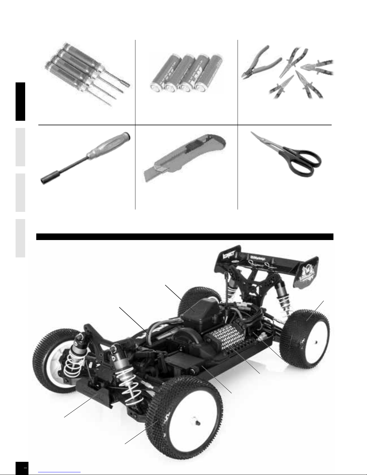
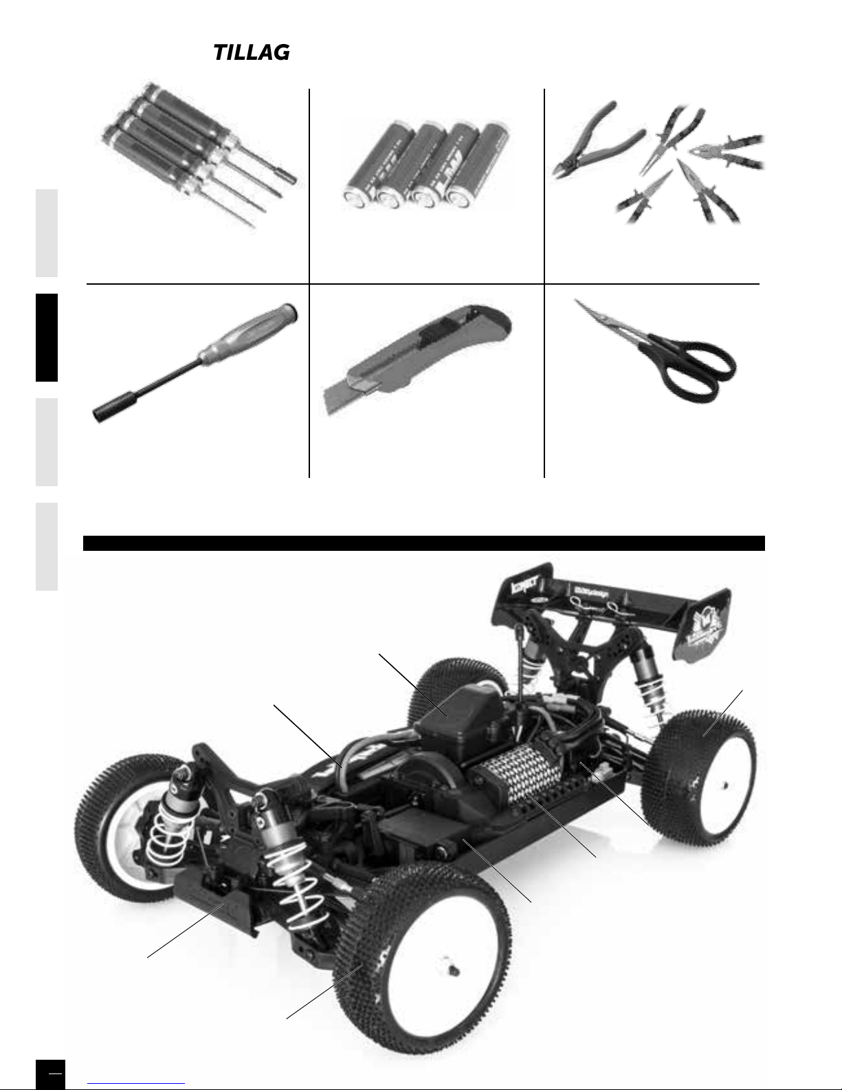
CHASSIS
Battery
holder
Receiver
Box
Steering
servo
ESC
Motor
Rear tyre
Front tyre
Front Bumper
ENGLISHFRAN
Ç
AISDEUTSCHESPAÑ OL
4
ENGLISHfraN
ç
a ISDEUTSCH
Curved lexan scissors
EX 421200
EX 421932
Nut driver 7mm
4xAA Alkaline batteries
TOOLS REQUIRED NOT INCLUDED IN THE KIT
Multifonction pliers complety set
Knife
HT 421910
1-10 scale full tool set
Hex wrench 1,5-2mm
Philips 1.5mm
Nut driver 5.5mm
Page 5
ENGLISHFRAN
Ç
AISDEUTSCHESPAÑ OL
5
F
unctions
Battery LED Indicator
Battery Installation
Warning: Never disassemble batteries or put the batteries in fire, chemical
agents, otherwise they may cause personal injuries or property damages.
Battery Disposal: Observe corresponding regulations about wasted battery
treatment regulations.
1. After running out of power, dispose of wasted batteries in designated
areas far away from water supply, household areas and planted areas.
2. Submit the wasted batteries to specific recycling stations.
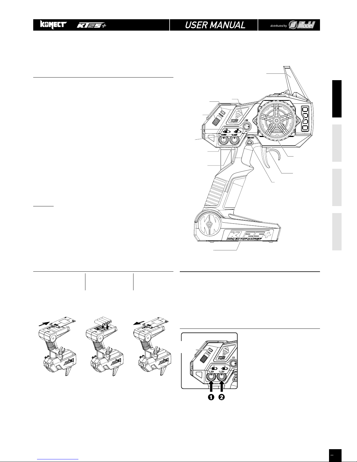
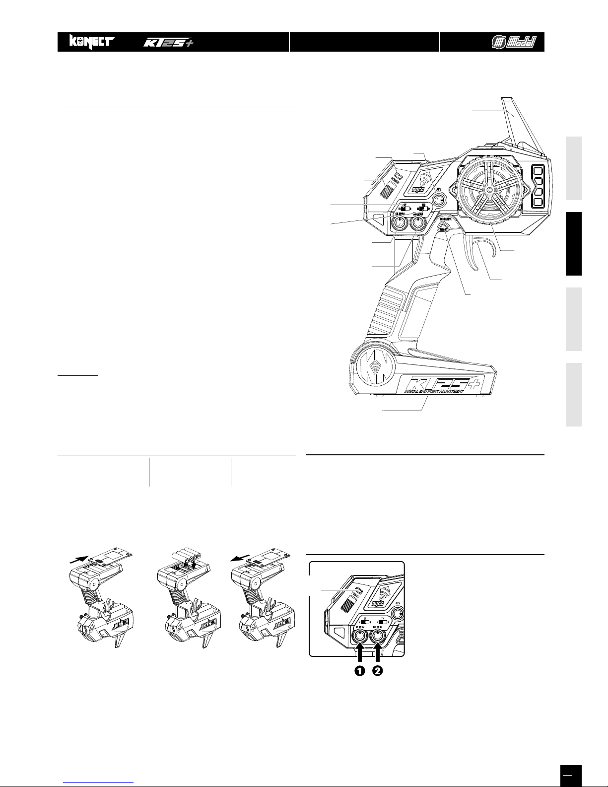
KT2S+ Transmitter
Steering Wheel : Control direction (Left / Right) of the RC
model.
Throttle Trigger : Control speed and direction (Forwar-
d/Brake/Backward) of the driving model.
Battery Compartment Tray : Cover and hold the batteries powering the
transmitter.
Antenna : Transmit signal to the model
Power ON / OFF : Power ON / OFF the transmitter
SYNC & Battery Indicator : Top Green LED light indicates synchroni-
zation status
and/or adequate battery power supply.
ATV : Adjustable Steering Rate by ATV dial
ST. Trim Dial : Adjust the neutral position of steering
servo when model wheels are straight
ahead.
TH. Trim Dial : Make sure the model stays still when
releasing the throttle trigger.
EPA : End Point Adjustment
WARNING
: accidental or intentional EPA function manipulation
may cause servos malfunction (reduced or inexistant travel).
Please reset maximum default values before contacting your
dealer (see «EPA», on page 7).
Works with 4 x 1.5V AA
Batteries (not provided),
KT2S+ can be operated a
few hours. Installation:
Remove the batte
ry
compartment cover as
shown belo
w.
Install the batteries
observing the polarity
marked on battery
compartment.
Then reicompartment cover as the
picture shown
below.
- During normal operation, the LED should be solid green ON-
- When battery voltage is dropped below 3.8V, the LED will become red
color and flashing very slowly, to indicate battery is low, you should replace
new battery as soon as possible
* Always turn on the transmitter first by sliding the switch on the left side
from bottom to top. The green lights above the switch should light up. If not,
you need to check for low or incorrectly installed batteries.
1. Steering : Adjust the steering trim to
keep the front wheels in straight line
when steering wheel remains in
NEUTRAL position.
2. Throttle : Adjust the throttle trim to
ensure the wheels stop rotating when
throttle trigger remains in NEUTRAL
position (only for nitro).
For EP vehicles, this button must be
set to NEUTRAL (See «1- The neutral
point on page 9).
Pre-Run Check
LED
indicatorIndicator
LED
Battery
Compartment Tray
Steering Trim Dial
Steering Wheel
Throttle Trigger
Throttle Trim Dial
BIND / EPA Key
Antenna
Power Indicator
ATV
Power
ON / OFF
Throttle
Reverse Switch
Steering
Reverse Switch
TRANSMITTER
EVEN IF THIS CAR IS A READY TO RUN KIT, YOU STILL HAVE SOME LITTLE THINGS TO DO TO FAMILIARI ZE WITH YOUR
PRODUCT.
PLEASE FOLLOW THESE STEPS.
Page 6
ENGLISHFRAN
Ç
AISDEUTSCHESPAÑ OL
6
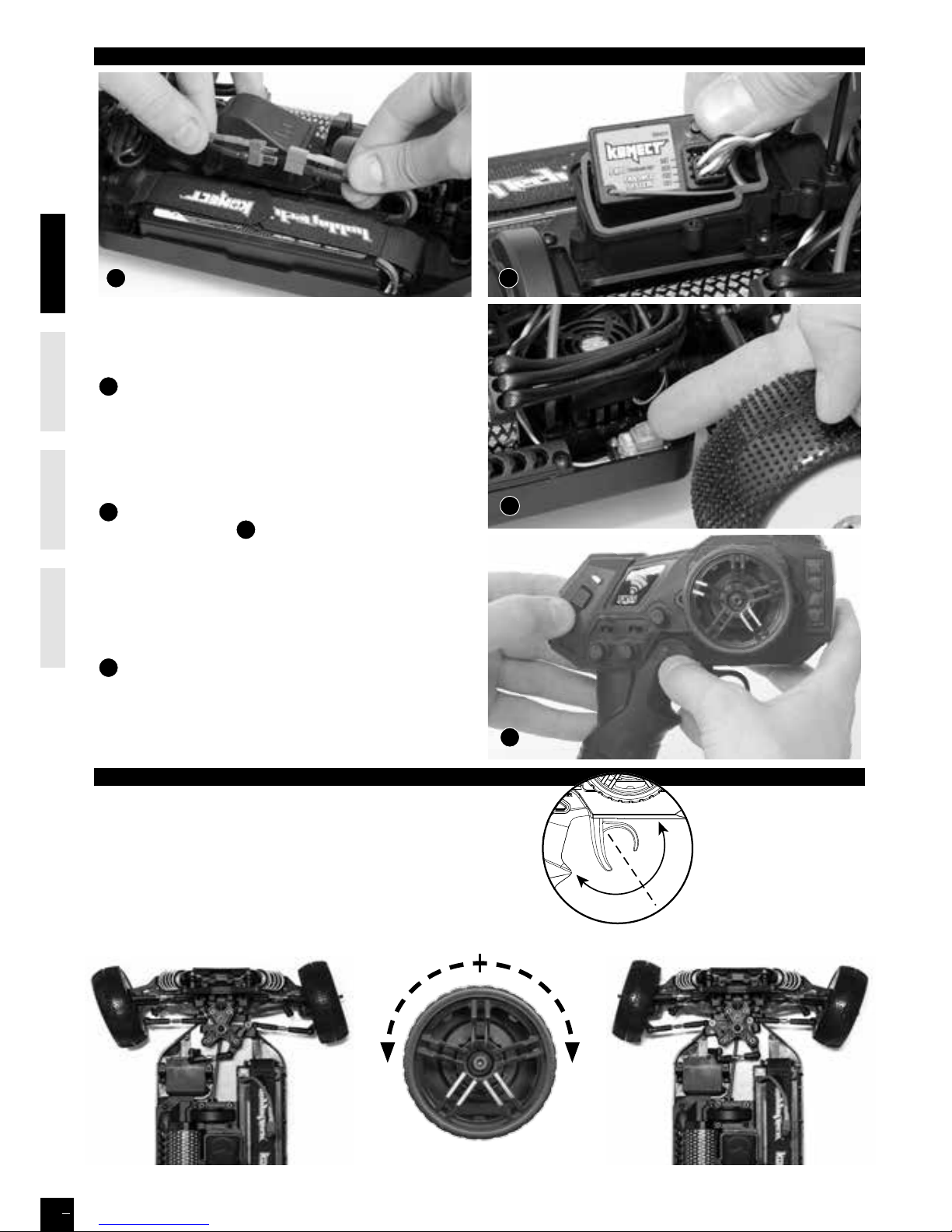
Pairing your receiver to your KT2S+
Place model on a block to prevent wheels from touching the
ground.
A
Connect battery to ESC. Fix the wire correctly with the
provided connectors.
You must check the signal of transmitter and receiver before
you operating it at first.
Make sure TH Trim is on neutral
TURN OFF THE TRANSMITTER AND RECEIVER
B
Press and Hold the BIND button on the receiver while
turning on the receiver
C
.
Release the BIND button when the LED flashes red.
While the red LED flashes, press the BIND button to select the
frame rate.
- Faster flashes= high frame rate (7ms), for digital servo
- Slower flashes= low frame rate (15ms), for analog servo
D Press and Hold the BIND/EPA key of the Transmitter (1),
and then turn on the transmitter (2), LED flahes green and the
Transmitter will communicate with the receiver. Release the
BIND/EPA button when the receiver LED is solid red, and the
transmitter is solid green, then your receiver is paired with your
transmitter.
BIND
A
C
B
D
(1)
(2)
HOW TO CONTROL YOUR MODEL
NEUTRAL POSITION
1. Pull up the trigger in order to brake or speed down
2. Pull the trigger in order to go forward or speed up
BRAKE / SPEED
DOWN POSITION
FORWARD / SPEED
UP POSITION
If the wheels operate in the opposite direction,
operate the servo reverse switch (ST in position NOR).
NEUTRAL
LEFT RIGHT
Page 7
ENGLISHFRAN
Ç
AISDEUTSCHESPAÑ OL
7
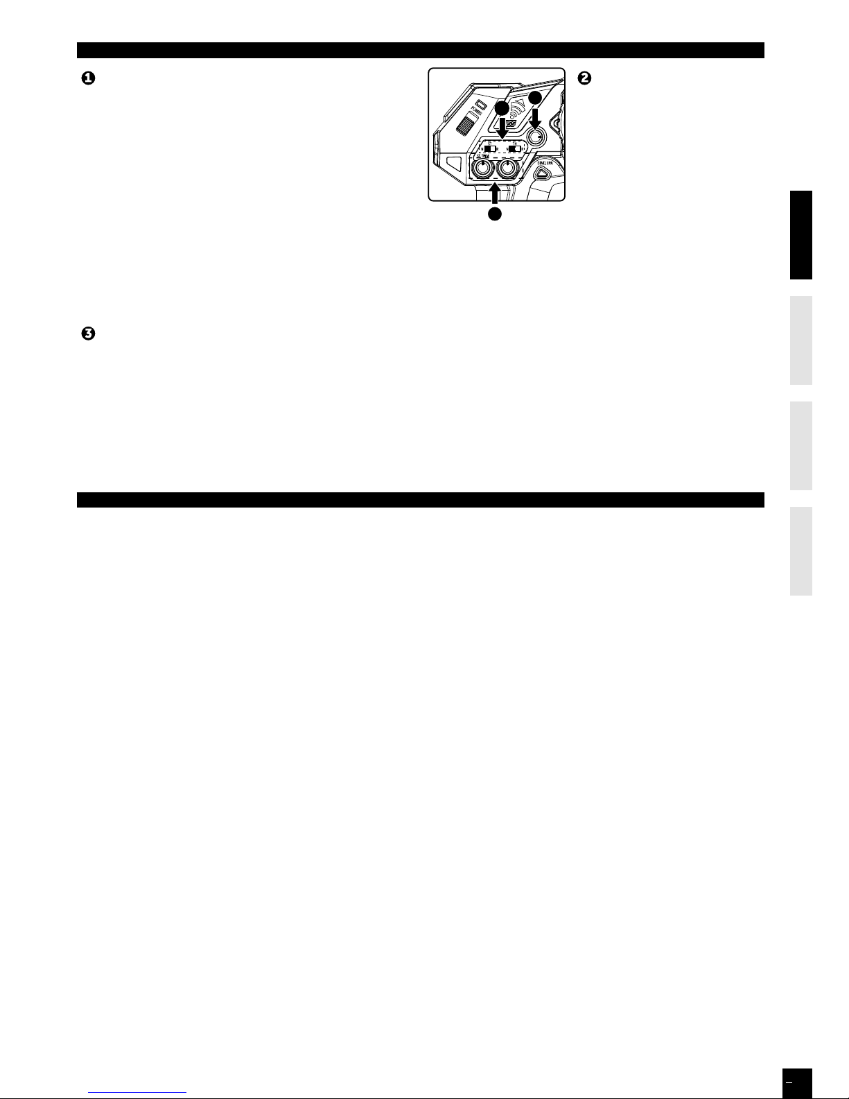
ABOUT THE RADIO SYSTEM
Reversing is used to change the response direction of steering
wheel and throttle trigger.
KT2S+ Transmitter features 2 reversing functions: Steering Reverse
and Throttle Reverse.
Steering Reverse: Reverse the response direction when operating
steering wheel.
Turning left steering wheel, the model turns right while turning
right the model turns left.
Throttle Reverse: Reverse the response direction when operating
throttle trigger.
Pushing forward throttle trigger the model moves backward while
pulling back, the model moves forward.
Adjustable Steering Rate enables to adjust the same maximum steering angle of servo on both sides (Left and Right) when
model makes steering. The Adjustable Steering Rate aects the sensitivity of servo. Reducing dual rate value can lower the
sensitivity of servo and reduce the same maximum steering angle on both sides. Remember to adjust the dual rate value within
the adjustment range: rotate clockwise = increase maximum steering angle; rotate counterclockwise = reduce maximum
steering angle.
The minimum adjustment of ATV (counterclockwise to the max) makes a zero steering angle.
KT2S+ features two trimming
functions:
Steering Trim and Throttle Trim.
Steering Trim Dial: Adjust the
neutral position of steering servo
when the wheels are straight
ahead.
Normally steering trim is adjusted
until the model can keep straight
tracks.
Throttle Trim Dial:
Adjust neutral position of throttle servo. Make sure the model
stays still when releasing the throttle trigger.
Reversing
Adjustable Steering Rate (ATV)
Trimming
PROGRAMMING THE END-POINTS
In order to avoid mechanical strain when steering to the maximum and/or accelerating and braking (nitro), an EPA function
(End Point Adjusment) can be digitally set. However ATV function can be used for steering end points, but on the left & right
together.
If you really want to use EPA function, please read the following instructions carefully:
1. Steering servo
a) Transmitter and receiver powered on (green LED on), turn the steering wheel to the maximum (on the side you want to set),
then hold down for 2 seconds the «BIND/EPA» button: LED turns solid red.
b) As long as LED is red, you can set the exact maximum turning angle of the wheels on the side you choose.
Once the angle is chosen, hold down again for 2 seconds the «BIND/EPA» button. LED flashes twice (light green/dark green)
then turns solid green.
IMPORTANT: Switch OFF and ON the transmitter to confirm the adjustment.
c) To reset the default value, follow a) step, then b) step, hold the steering wheel to the maximum and hold down for 2 seconds
the «BIND/EPA» button. LED flashes twice (light green/dark green) then turns solid green. IMPORTANT: Switch OFF and ON the
transmitter to confirm the adjustment.
To set the opposite side, follow a) and b) steps in the opposite side.
It is very important to perform these operations one by one.
2. Throttle servo (EPA is recommended only for nitro vehicles)
a) Transmitter and receiver powered on (green LED on), hold the throttle at forward-most position, then hold down for 2
seconds the «BIND/EPA» button: LED turns solid red.
b) As long as LED is red, you can set the exact your max throttle end-point.
Once the end-point is chosen, hold down again for 2 seconds the «BIND/EPA» button. LED flashes twice (light green/dark
green) then turns solid green.
IMPORTANT: Switch OFF and ON the transmitter to confirm the adjustment.
c) To reset the default value, follow a) step, then in b) step, hold the throttle at forward-most position, then hold down for 2
seconds the «BIND/EPA». LED flashes twice (light green/dark green) then turns solid green.
IMPORTANT: Switch OFF and ON the transmitter to confirm the adjustment.
To set the brake, follow a) step, then b) step braking to the maximum. You can now set your maximum brake end-point.
It is very important to perform these operations one by one.
3
2
4
Page 8
ENGLISHFRAN
Ç
AISDEUTSCHESPAÑ OL
8
High power system for RC model can be very dangerous, so we strongly suggest you read this manual carefully. In that
KONECT have no control over the correct use, installation, application, or maintenance of our products, no liability shall be
assumed nor accepted for any damages, losses or costs resulting from the use of the product.
ANY CLAIMS ARISING FROM THE OPERATING, FAILURE OF MALFUNCTIONING ETC. WILL BE DENIED. WE ASSUME NO LIABILITY FOR
PERSONAL INJURY, CONSEQUENTIAL DAMAGES RESULTING FROM OUR PRODUCT OR OUR WORKMANSHIP. AS FAR AS IS LEGALLY
PERMITTED, THE OBLIGATION TO COMPENSATION IS LIMITED TO THE INVOICE AMOUNT OF THE AFFECTED PRODUCT.
FEATURES
1. Specially designed for RC car and truck, with excellent start-up, acceleration and linearity features.
2. Compatible with sensorless brushless motor.
3. 2 running modes suitable for dierent applications (“Racing” mode, “General”).
4. Proportional ABS brake function with 4 steps of maximum brake force adjustment, 8 steps of drag-brake force adjustment
and 4 steps of initial brake force adjustment.
5. 4 start modes (“Punch”) from “Soft” to “Very aggressive” to be suitable for dierent chassis, tires and tracks.
6. Multiple protection features: Low voltage cut-o protection for lithium or nickel battery / Over-heat protection / Throttle
signal loss protection / Motor blocked protection.
7. User programmable. Two program methods are supported: The “SET” button on the ESC, the digital LED program card.
The program card is pocket-sized and has friendly user interface to be easily used.
8. Waterproof and Dustproof.
SPECIFICATIONS
Model KONECT 50AMP WP “by HOBBYWING”
Cont. / Burst Current 50A / 300A
Resistance 0.0010ohm
Suitable Car 1/10 scale on-road / o-road
Motor Limit
2S LiPo 6 cells NiMH
On-road ≥ 8T
O-road ≤ 11T
3650 size motor
3S LiPo 9 cells NiMH
On-road ≥ 11T
O-road ≤ 14T
3650 size motor
Battery
4-9 cells NiMH
2-3 cells Li-Po
BEC Output 6V/2A
Motor Type Sensorless brushless motor
Dimension & weight 48.5*38*32 & 90g
BEGIN TO USE THE NEW ESC
WARNING! THIS BRUSHLESS SYSTEM IS VERY POWERFUL!
FOR SAFETY, PLEASE ALWAYS KEEP THE WHEELS AWAY FROM
THE TRACK WHEN YOU BEGIN TO SWITCH ON THE ESC.
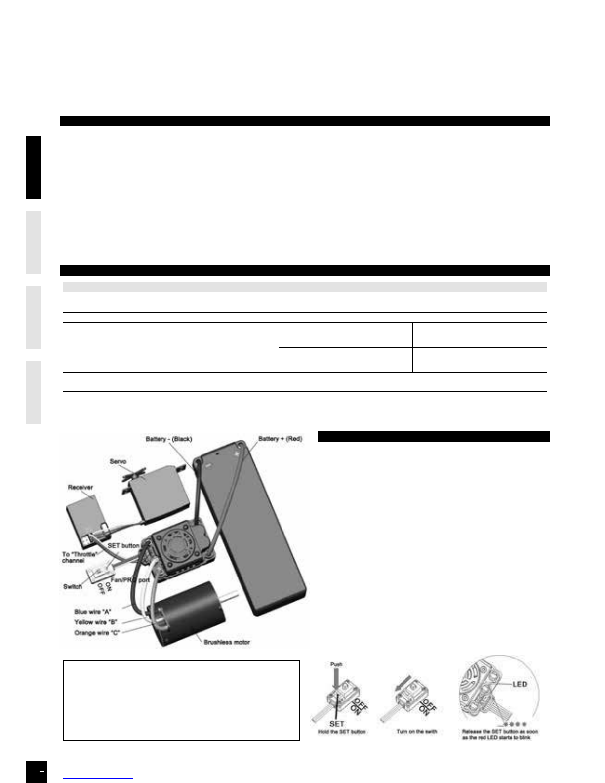
1. Connect the ESC, motor, receiver, battery and servo
according to the following diagram
The #A, #B, #C wires of the ESC can be connected with
the motor wires freely (without any order). If the motor
runs in the opposite direction, please swap any two wire
connections.
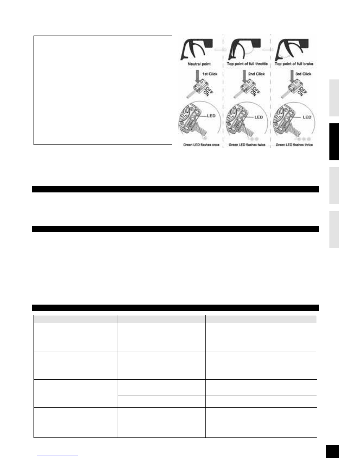
2. Throttle Range Setting (Throttle Range Calibration)
In order to make the ESC fit the throttle range, you must
calibrate it when you begin to use a new ESC, or a new
transmitter, or change the settings of neutral position of the
throttle stick, ATV or EPA parameters, etc. Otherwise the
ESC cannot work properly.
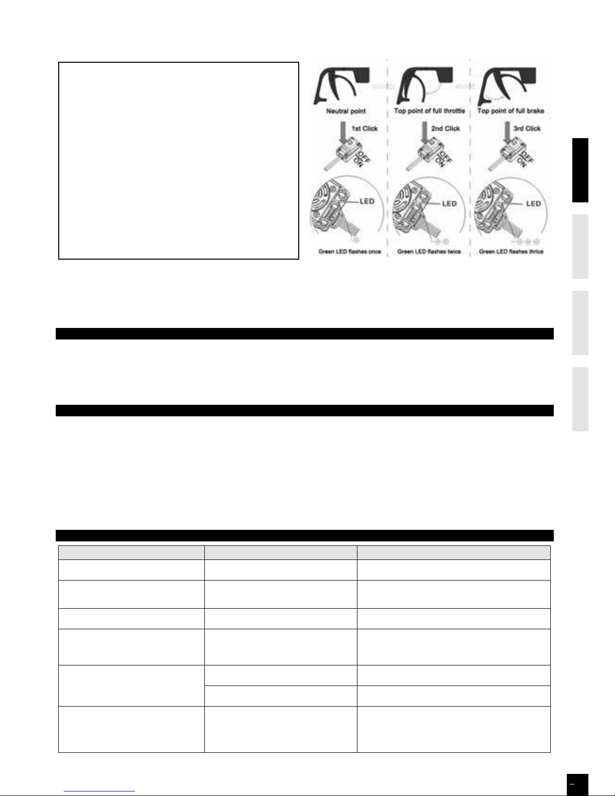
There are 3 points need to be set, they are the top point of
“forward”,” backward” and the neutral point.
The following pictures show how to set the throttle range
with a Futaba
TM
transmitter.
A) Switch o the ESC, turn on the transmitter”, set the
“EPA/ATV” value of throttle channel to “100%”, and
disable the ABS function of your transmitter.
B) Hold the “SET” key and then switch on the ESC, and
release the “SET” key as soon as possible when the red
LED begins to flash. (Note 4)
50
amp
BRUSHLESS WATERPROOF ESC - INSTRUCTION MANUAL
Page 9
ENGLISHFRAN
Ç
AISDEUTSCHESPAÑ OL
9
Note4: If you don’t release the “SET” key after the red LED begins to flash, the ESC will enter the program mode, in such a case,
please switch o the ESC and re-calibrate the throttle range again from step A.
C) Set the 3 points according to the steps shown as the
pictures on the right side.
1) The neutral point
Move the throttle stick at the neutral point, and then
click the SET key, the green LED flashes 1 time.
2) The end point of forward direction
Move the throttle stick at the end point of forward
direction, and then click the SET key, the green LED
flashes 2 times.
3) The end point of backward direction
Move the throttle stick at the end point of backward
direction, and then click the SET key, the green LED
flashes 3 times.
D) Throttle range is calibrated; motor can be started after
3 seconds.
3. Check the LED Status in Normal Running
1) Normally, if the throttle stick is in the neutral range, neither the red LED nor the green LED lights.
2) The red LED lights when the car is running forward or backward.
3) The green LED lights when the throttle stick is moved to the top point (end point) of the forward zone.
ALERT TONES
1. Input voltage abnormal alert tone: The ESC begins to check the input voltage when power on, if the voltage is out of the
normal range, such an alert tone will be emitted: “beep-beep-, beep-beep-, beep-beep-” (There is 1 second interval between
every “beep-beep-” tone).
2. Throttle signal abnormal alert tone: When the ESC can’t detect the normal throttle signal, such an alert tone will be emitted:
“beep-, beep-, beep-” (There is 2 seconds interval between every “beep-” tone).
PROTECTION FUNCTION
1. Low voltage cut-o protection: if the voltage of a LiPo battery pack is lower than the threshold for 2 seconds, the ESC will
cut o the output power. Please note that the ESC cannot be restarted if the voltage of each LiPo cell is lower than 3,5V.
For NiMH battery packs, if the voltage of the whole NiMH battery pack is higher than 9.0V but lower than 12V, it will be
considered as a 3S LiPo; if it is lower than 9.0V, it will be considered as a 2S LiPo. For example, if the NiMH battery pack is 8.OV,
and the threshold is set to 2,6V/cell, it is considered as a 2S LiPo, and the low-voltage cut-o threshold for this NiMH battery
pack is 2.6 x 2 = 5.2V.
2. Over-heat protection: when the temperature of the ESC is over a factory preset threshold for 5 seconds, the ESC will cut o
the output power. You can disable the over-heat protection function for competition race.
3. Throttle signal loss protection: the ESC will cut o the output power if the throttle signal is lost for 0.2 second.
TROUBLE SHOOTING
TROUBLE POSSIBLE REASON SOLUTION
After power on, motor doesn’t work, and the
cooling fan doesn’t work
The connections between battery pack and ESC
are not correct
Check the power connections
After power on, motor can’t work, but emits
“beep-beep-, beep-beep-” alert tone. (Every
“beep-beep-” has a time interval of 1 second )
Input voltage is abnormal, too high or too low Check the voltage of the battery pack
After power on, red LED always lights, the
motor doesn’t work
Throttle signal is abnormal
Plug the control wire into the throttle channel of the receiver
correctly.
The motor runs in the opposite direction
when it is accelerated
1) The wire connections between ESC and the
motor are not correct
2) The chassis is dierent from the popular
design
Method #1: Swap any two wire connections between the
ESC and the motor
Method #2: Change the “Motor Rotation” programmable
item to “CW(Clockwise)”
The motor suddenly stops running while in
working state
The throttle signal is lost
Check the transmitter and the receiver
Check the signal wire from the throttle channel of your receiver
The ESC has entered the Low Voltage
Protection Mode or Over-heat Protection Mode
Red LED flashes means Low Voltage Green LED flashes
means Over-heat
Random stop or restart irregular working
state
1) Some connections are not reliable
2) Wrong charge of the battery pack
3) Gear ratio is too long
4) Start mode (punch) is too agressive
1) Check all the connections: battery pack connections,
throttle signal wire, and motor connections, etc.
2) Replace the battery pack
3) Change the gear ratio
4) Go down the Start Mode to a softer value
Page 10
ENGLISHFRAN
Ç
AISDEUTSCHESPAÑ OL
10
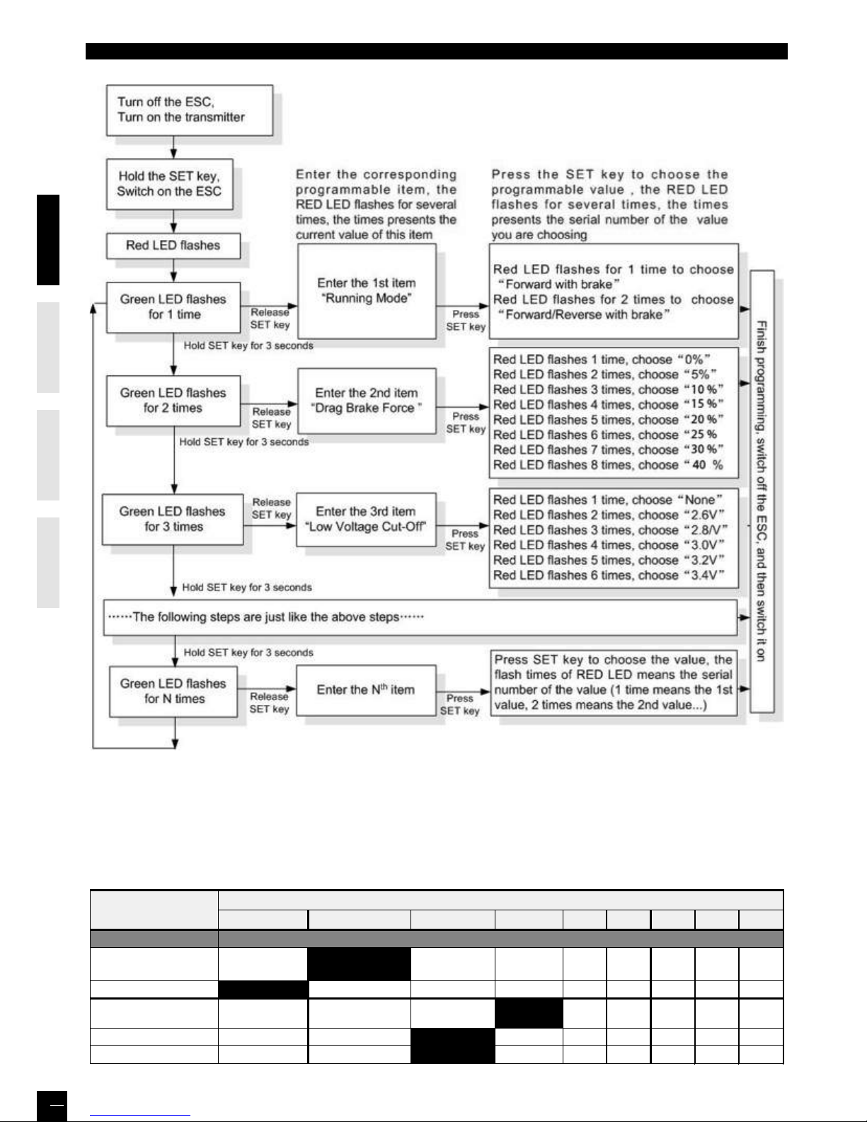
PROGRAM THE ESC
1. Program Method
Note5: • In the program process, the motor will emit “Beep” tone at the same time when the LED is flashing.
• If the “N” is bigger than the number “5”, we use a long time flash and long “Beep---” tone to represent “5”, so it is
easy to identify the items of the big number.
For example, if the LED flashes as the following:
“A long time flash + a short time flash” (Motor sounds “Beep---Beep”) = the No. 6 item
“A long time flash + 2 short time flash” (Motor sounds “Beep---BeepBeep”) = the No. 7 item
“A long time flash + 3 short time flash” (Motor sounds “Beep---BeepBeepBeep”) = the No. 8 item …… And so on.
Programmable Items List
(Italic texts in the above form are the default settings)
1 2 3 4 5 6 7 8
1. Running Mode
Forward Only
with Brake
Forward/Reverse
with Brake
2. Drag Brake Force
3. Low Voltage
Cut-Off Threshold
Non-Protection 2.6V/Cell 2.8V/Cell
3.2V
/Cell
3.4V
/Cell
4. Start Mode (Punch) Level1 Level2
5. Max Brake Force 25%
9
Programmable
Items
Basic Items
Programmable Value
3.0V
/Cell
10% 20% 40% 60% 80% 100%
100%
5%
Level4
Level3
75%
0%
50%
Page 11
ENGLISHFRAN
Ç
AISDEUTSCHESPAÑ OL
11
2. Programmable Values
2.1. Running Mode: With “Forward Only with Brake” mode, the car can go forward and brake, but cannot go backward, this mode
is suitable for competition; “Forward/Reverse with Brake” mode provides backward function, which is suitable for daily training.
Note: “Forward/Reverse with Brake” mode uses “Double-click” method to make the car go backward. When you move the
throttle stick from forward zone to backward zone for the first time (The 1st “click”), the ESC begins to brake the motor, the motor
speeds down but it is still running, not completely stopped, so the backward action is NOT happened immediately. When the
throttle stick is moved to the backward zone again (The 2nd “click”), if the motor speed is slowed down to zero (i.e. stopped),
the backward action will happen. The “Double-Click” method can prevent mistakenly reversing action when the brake function
is frequently used in steering.
2.2. Drag Brake Force: Set the amount of drag brake applied at neutral throttle to simulate the slight braking eect of a neutral
brushed motor while coasting.
2.3. Low Voltage Cut-O: The function prevents the lithium battery pack from over discharging. The ESC detects the
battery’s voltage at any time, if the voltage is lower than the threshold for 2 seconds, the output power will be cut o, and the red
LED flashes in such a way: “❏-❏-, ❏-❏-, ❏-❏-”.
There are 6 preset options for this item. You can customize the cuto threshold by using a LCD program box (optional equipment)
to trim it with a step of 0.1V, so it will be more suitable for all kinds of batteries (NiMH, NiCd, Li-ion, Lipo, LFP,etc). Please always
keep in mind that the customized value is not for each cell, it is for the WHOLE battery pack.
2.4. Start Mode (Also called “Punch”): Select from “Level1” to “Level4” as your like, Level1 has a very soft start eect, while level4
has a very aggressive start eect. From Level1 to Level4, the start force is increasing.
2.5. Maximum Brake Force: The ESC provides proportional brake function. The brake force is related to the position of the
throttle stick. Maximum brake force refers to the force when the throttle stick is located at the top point of the backward zone.
A very large brake force can shorten the brake time, but it may damage the gears.
3. Reset All Items To Default Values
At any time when the throttle is located in neutral zone (except in the throttle calibration or parameters program process), hold
the “SET” key for over 3 seconds, the red LED and green LED will flash at the same time , which means each programmable item
has be reset to its default value.
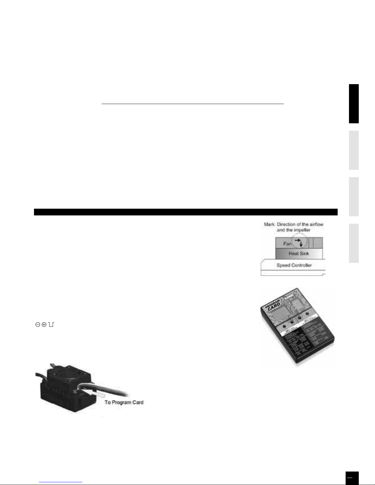
OPTIONAL ACCESSORIES
1. Cooling fan (12V)
The high voltage fan is necessary when you use 3S LiPo or Ni-MH battery more than 6
cells.
WARNING! Please note the original cooling fan (5V) is only recommended to work with
2S LiPo or 4-6 cells Ni-MH battery. Please DON’T use it with a 3S LiPo or Ni-MH battery
more than 6 cells.
Please check the label of the cooling fan carefully to confirm its working voltage
before using it.
2. LED Program Card
Program card is an optional equipment which needs to be purchased separately. It has
a friendly user interface. The process of programming the ESC becomes quite easy and
fast with this pocket sized device. When the programmable value needs to be changed,
please just plug the control wires of the ESC (trio wires with black, red and white color)
into the socket of the program card (The socket is on the right corner, and marked with
), and then connect the main battery pack to the ESC. After several seconds,
each item’s value will be shown on the program card. Use “ITEM” and “VALUE” buttons
to select the programmable items and new values, and then press “OK” button to store
the new settings into the ESC.
• The program port is multiplexed with the cooling fan port, please disconnect the cooling fan, and then use program cable to
connect the fan port of the ESC to the LED program card.
Item # KN-PROGRAM-CARD
Page 12
ENGLISHFRAN
Ç
AISDEUTSCHESPAÑ OL
12
GARANTIE DE 90 JOURS
MERCI DE LIRE ATTENTIVEMENT LES LIGNES CIDESSOUS :
A partir de la date d’achat, le produit est couvert par une garantie de 90 jours couvrant les composants. Si durant cette période, une des pièces composant votre
produit (hormis les pièces de transmission) possède un défaut de fabrication réellement constaté par notre service technique, la pièce sera réparée ou échangée.
Une fois cette nouvelle pièce utilisée, elle ne sera plus garantie.
Il est important de savoir que ce produite n’est en aucun cas un jouet, il est recommandé aux moins de 14 ans uniquement sous la surveillance d’un adulte. Il est de
la responsabilité des parents ou du tuteur de garantir que les moins de 14 ans ont une supervision nécessaire.
Lors de l’utilisation, si vous vous apercevez qu’il existe un problème avec le produit, il est de la responsabilité de l’acquéreur de rechercher et de corriger le
problème avant de causer des dommages plus importants.
NON GARANTIE
Ce produit est un modèle de haute performance et sophistiqué, il sera dans tous les cas traité avec soins et respect. Au niveau conception et choix des matières,
tout a été fait pour vous apporter un produit endurant et robuste. Toutefois, lors d’utilisation sévère et anormale, il est possible de casser et d’endommager les
pièces composantes le modèle.
La garantie ne couvre pas l’usure normale d’un produit ni la casse résultant de son utilisation. Elle ne s’applique pas non plus à la réparation de dommages
résultant d’une cause externe à l’appareil (par exemple d’un accident, d’un choc, de la foudre, de la tempête, de la présence d’eau (et plus généralement tous corps
étrangers à l’appareil, d’une fluctuation de courant, d’une oxydation…), d’une installation ou d’un branchement non conformes aux spécifications ou prescriptions
du constructeur, d’une utilisation nuisible à la bonne conservation de l’appareil, d’une utilisation à caractère professionnel, de l’utilisation de périphériques,
d’accessoires ou de consommables inadaptés, ou encore aux appareils démontés ou modifiés.
MISE EN PLACE DE LA GARANTIE
Dans un premier temps, veuillez retourner le produit chez votre revendeur, en tant que professionnel il vous conseillera sur la possibilité ou pas de la prise en
garantie.
Surtout, n’envoyez pas le produit directement chez le distributeur avant d’avoir vu votre revendeur et/ou sans l’accord du distributeur.
Vous n’avez pas à envoyer le produit en entier, seulement l’élément défectueux avec le formulaire qui vous sera transmis en amont. Dans tous les cas, ces frais
d’expédition sont à votre charge. Dans beaucoup de cas, il est plus rapide et rentable pour l’utilisateur de remplacer directement la pièce.
Attention, toute pièce retournée et inspectée par le service technique du distributeur qui ne s’avère pas prise en garantie, peut être sujette à des frais d’inspection,
de manipulation et de retour à votre charge. Si le produit défectueux demande une réparation et ne rentre pas dans les conditions couvertes par la garantie, ces
réparations vous seront facturées au prix horaire en cours applicable par le service technique du distributeur.
Si vous décidez de ne réaliser aucun travail de réparation, le distributeur se réserve le droit de facturer les frais d’inspection, de manipulation et d’expédition.
Nous vous conseillons de garder précieusement votre preuve d’achat, elle pourrait vous être utile.
ÉMETTEUR ET RÉCEPTEUR KONECT KT2S+
FCC ID: YDTHBT1000
FCC Statement : Cet équipement a été testé et déclaré conforme aux limites pour appareils numériques de section 15 des règlements de la FCC. Ces limites sont destinées à assurer une
protection raisonnable contre les interférences nuisibles dans une installation résidentielle.
Cet équipement produit, utilise et peut émettre de l’énergie radio électrique et, s’il n’est pas installé et utilisé conformément aux présentes instructions, peut causer des interférences nuisibles
aux communications radio.
Quoi qu’il en soit, on ne peut pas garantir que des interférences ne se produiront pas dans certaines installations. Si cet appareil cause des interférences nuisibles à la réception des signaux de
radio ou de télévision, ce qui peut être déterminé en allumant et en éteignant l’appareil, on encourage l’utilisateur d’essayer de corriger ces interférences par l’un des moyens suivants :
• Réorienter ou repositionner l’antenne de réception. • Augmenter la distance séparant l’équipement du récepteur.
• Branchez l’appareil sur un circuit électrique diérent de celui où le récepteur est branché.
Ce dispositif est conforme à la section 15 des réglementations de la FCC. Son fonctionnement est soumis aux deux conditions suivantes :
(1) Cet appareil ne doit pas causer d’interférences nuisibles,
(2) Cet appareil doit accepter toute autre interférence reçue, y compris les interférences pouvant entraîner un fonctionnement non désiré.
Note : Toute modification du dispositif peut annuler la capacité de l’acheteur à utiliser l’appareil.
DÉCLARATION DE CONFORMITÉ SELON LA DIRECTIVE R&TTE 1999/05/CE
Sarl Imodel
5 place de Rome
13006 Marseille
France
Declare que le produit suivant : BXRS1
w/ KONECT KT2S+ Émetteur & récepteur
Référence article: 1.BXR.S1.RTR
Catégorie d’équipement : 1
Correspond aux exigencies essenttieles de la directive FTEG (Article 3 de la directive
R&TTE)
• Protection de la santé et de la sécurité de l’utilisateur et de toute autre personne
conformément à l’article 3.1.a
Norme appliqué : EN 62311:2008
• Exigence en matière de protection en rapport à la compatibilité électromagnétique
(article 3.1b)
Normes appliquées : EN 301 489-1 V1.9.2 (2011-09)
EN 301 489-3 V1.4.1 (2002-08)
• Utilisation ecace du spectre attribué aux communications radio terrestres ou spatiales
ainsi que les ressources orbitales pour éviter les interférences dommageables (article 3.2).
Normes appliquées: EN 300 440-1 V1.6.1 (2010-08)
EN 300 440-1 V1.4.1 (2010-08)
Adresse du fabricant : Sarl Imodel
5 place de Rome
13006 Marseille
France
Date de délivrance : 27 septembre 2012
Ce pictogramme indique que le produit ne doit pas être traité
comme déchet ménager. Vous devez veiller à éliminer ce produit
correctement afin d’éviter toute atteinte à l’environnement
et à la santé humaine. Un traitement ou une mise au rebut
inappropriés de ce produit pourraient avoir des conséquences
négatives sur l’environnement et la santé humaine. Aidez-nous
à respecter l’environnement !
i.A.
Page 13

ENGLISHFRAN
Ç
AISDEUTSCHESPAÑ OL
13
IMPORTANT LIRE AVANT DE DÉMARRER
LIRE CES INSTRUCTIONS ET SE FAMILIARISER AVEC LE PRODUIT AVANT DE S’EN SERVIR.
Ce produit n’est pas un jouet. C’est un modèle réduit de haute performance. Il est important de se familiariser avec le modèle,
son manuel et sa construction avant l’assemblage et le fonctionnement. La surveillance d’un adulte est nécessaire.
ATTENTION
Afin d’éviter tout dommage à des personnes ou à des biens, utiliser le modèle radio-commandé de manière responsable
comme décrit ci-après. Les modèles radio commandés peuvent atteindre des vitesses supérieures à 40km/h (25mph) et ne
peuvent s’arrêter instantanément.
❶ Ne jamais conduire le modèle radio-commandé sur les routes et dans les rues car il pourrait provoquer des accidents qui
causeraient de graves dommages.
❷ Ne pas rouler près de personnes ou d’animaux. Ne pas utiliser les personnes ou animaux comme obstacles.
❸ Pour éviter tout dommage aux personnes et animaux, ne pas conduire dans un endroit bruyant ou trop exigu.
❹ Piloter le modèle radio-commandé à l’intérieur entre des objets statiques peut causer des dommages aux objets et au
modèle radio-commandé.
PRÉCAUTIONS À OBSERVER PENDANT L’UTILISATION
Lorsque le modèle R/C est en marche, ne jamais toucher les parties en mouvement (transmission, roues, engrenages…)
❶ Quand le modèle roule, son moteur fonctionne continuellement et il chaue. Il peut atteindre une température élevée.
Ne pas le toucher, risque de brûlures. Faire Attention !
❷ S’assurer que personne n’utilise la même fréquence. Si c’est le cas, le contrôle du modèle risque d’être perdu et causer des
accidents.
❸ Préserver tous les fils des frottements et des pièces en rotation. Veiller à ce que les connecteurs soient bien enfichés et les
sécuriser avec la gaine thermorétractable ou de la bande adhésive d’isolation. Fixer les câbles au châssis avec des colliers en
nylon. Réparer immédiatement les fils et les connexions endommagés.
❹ Le moteur risque d’être endommagé si toutes les pièces en mouvement ne tournent pas librement : roues, axes de
transmission, pignonnerie…Le moteur risque de chauer plus que la normale, il consommera plus d’énergie et diminuera
l’autonomie de l’accu. Il est important de vérifier régulièrement que toutes ces pièces et le moteur sont en bon état.
Dans le cas contraire, les changer immédiatement.
❺ Si l’accu devient trop faible pour alimenter le récepteur, le contrôle du modèle est perdu. Arrêter le modèle quand il
commence à ralentir pour éviter de perdre le contrôle.
CONSIGNES DE SÉCURITÉ
- Ne pas faire fonctionner le modèle au milieu d’enfants ou de la foule.
- Vérifier que personne d’autre n’utilise la même fréquence dans le même secteur car cela pourrait provoquer de sérieux incidents.
- Ne pas rouler dans l’eau ou sous la pluie. Si le moteur, le dispositif électrique ou l’accumulateur est mouillé, le sécher immédiatement.
Ordre de fonctionnement fondamental du modèle sans fil:
Allumer l’émetteur après avoir mis le trim de gaz à la position neutre.
❷ Brancher le contact du récepteur.
❸ Avant de faire fonctionner, s’assurer du bon fonctionnement des 2 voies de votre émetteur.
❹ Régler le trim du volant, agir sur le curseur pour que le modèle puisse avancer droit.
❺ Après avoir arrêté de conduire, arrêter le récepteur et ensuite la radiocommande.
❻ Débrancher tous les accumulateurs.
❼ A la fin de chaque fonctionnement, nettoyer l’ensemble du modèle.
RÉGLAGES
Pour augmenter les performances du modèle, il est nécessaire de le régler en fonction de la surface et du tracé du circuit sur lequel il
roulera. Faire les réglages en se référant aux instructions de ce manuel.
Garder à l’esprit que « l’équilibre » est le maître mot.
❶ Pneus - Le pneu a une grande influence sur les performances de la voiture et sont normalement les premiers composants qu’il faut
modifier en fonction du circuit. Sélectionner les bons pneus pour le circuit où le modèle roulera en fonction de la surface et/ou des
conditions atmosphériques.
❷ Pincement et ouverture - Régler le modèle avec un peu de pincement procure un meilleur maintien du cap en ligne droite mais
diminue le rayon de braquage. L’ouverture procure une direction plus marquée et plus incisive, elle permet de tourner plus court.
Exagérer les modifications réduira les facultés du modèle.
❸ Carrossage positif & négatif - Lorsque le modèle tourne dans un virage, il subit la force centrifuge qui le pousse à l’extérieur du
virage, cela provoque une perte d’adhérence et de stabilité. La surface de contact de chaque pneu avec le sol est déterminée par l’angle
de carrossage. La traction des pneus peut être augmentée ou diminuée en modifiant le carrossage.
Pour augmenter l’adhérence dans les virages il faut augmenter le carrossage négatif. Pour réduire l’adhérence, augmenter le carrossage
positif.
❹ Garde au sol & débattement de la suspension - La garde au sol et le débattement des suspensions ont un eet direct sur la stabilité
en virage, accélération, freinage. La garde au sol peut être ajustée en modifiant la tension des ressorts des amortisseurs.
❺ Rapport de transmission - Le bon rapport de transmission est déterminé par la puissance du moteur + le type d’accu + les
conditions du circuit. Il est à noter que rouler sur un circuit avec une bonne adhérence suggère d’utiliser un pignon d’1 dent plus petite
afin d’utiliser toute la capacité de l’accu.
Page 14
CHÂSSIS
ENGLISHFRAN
Ç
AISDEUTSCHESPAÑ OL
14
Ciseaux a lexan courbes
EX 421200
4 piles Alkaline R6
OUTILLAGE REQUIS NON INCLUS DANS LE KIT
Gamme multifonction de pinces
Cutter
HT 421910
Gamme d’outils complète 1/10
Clé allen 1,5-2mm
Tournevis cruciforme 1.5mm
Clé à douille 5.5mm
EX 421932
Clé à douille 7mm
Batterie
Boîte
récepteur
Servo de
direction
Contrôleur
Moteur
Pneu arrière
Pneu avant
Pare-chocs
Page 15
ENGLISHFRAN
Ç
AISDEUTSCHESPAÑ OL
15
F
onctions
Indicateur LED de batterie
Compartiment
porte-piles
ST.TRIM :
Trim de direction
Volant de
direction
Gâchette des gaz
TH.TRIM :
Trim gaz/frein
BIND (Synchronisation) /
EPA (Ajustement fin de course)
Antenne
Indicateur
de marche
ATV
POWER
ON / OFF
TH N-R :
Inversion gaz/frein
ST N-R :
Inversion de direction
Mise en place des piles
A
TTENTION
: Ne jamais essayer de démonter les piles ou de les jeter dans le
feu ou agents chimiques, ce qui pourrait provoquer des dommages
corporels ou des dégâts matériels.
Piles usagées:
Respecter la réglementation en vigueur sur le traitement
des batteries usagées.
1. Après être tombées en panne, se débarasser des batteries usagées dans
les zones désignées loin de tout point d’eau, zone domestique et agricole.
2. Déposer les batteries usagées dans les points prévus à cet effet.
L’émetteur KT2S
Volant de direction : Contrôle de la direction (Gauche/Droite) du
modèle
Gâchette des gaz :
Contrôle de la vitesse
(Marche avant / Frein / Marche arrière)
Compartiment porte-piles :
Maintient et couvre les piles qui
alimentent l’émetteur
Antenne : Transmet le signal au modèle
Power ON / OFF : Allume / Eteint l’émetteur
SYNC & indicateur de batterie :
La LED verte du haut indique le statut de
synchronisation et/ou l’alimentation
adéquate de la batterie
A
TV : Potentiomètre réglage fin de course
direction
S
T. Trim : Ajuste la position neutre du servo de
direction lorsque les roues du modèle sont
droites
TH.
Trim : Pour s’assurer que le modèle reste
immobile lorsque la gâchette des gaz est
relâchée
EPA électronique :
(End Point Adjusment = Ajustement des
fins de course)
Ajuste le débattement maximal des servos
de direction et de gaz/frein.
ATTENTION
: toute manipulation involontaire ou intentionnelle de
la fonction EPA peut entraîner des dysfonctionnements des
servos (débattement réduit ou nul dans certaines positions).
Merci de réinitialiser les valeurs maximales par défaut avant de
contacter votre revendeur. (voir «EPA», page 17)
Fonctionne avec 4 piles
1.5V AA ou batteries
rechargeables 1,2V AA (non
fournies), le KT2S+ peut
fonctionner plusieurs
heures.
Installation : Retirer le cache
du compartiment à piles
comme ci-dessous
Insérer les piles en
respectant les polarités
indiquées dans le
compartiment à piles
Remettre en place
le cache du
compartiment à
piles comme
indiqué ci-dessous
- Pendant une opération normale, la LED verte est allumée.
- Lorsque la tension descend sous 3.8V, la LED clignotera alternativement
Vert/Orange, pour indiquer que la batterie est faible. Remplacer les piles dès
que possible. ATTENTION : une batterie faible peut entraîner un dysfonctionnement du véhicule.
* Toujours allumer l’émetteur d’abord en faisant glisser l’interrupteur de bas
en haut. La lumière verte au-dessous de l’interrupteur doit s’allumer. Si ce
n’est pas le cas, vérifier que les piles ne soient pas usées, mal installées, ou
que la batterie ne soit pas déchargée.
1. Direction : Ajuster le Trim de direction
pour garder les roues avant en ligne
droite lorsque le volant de direction reste
en position neutre.
2. Gaz / Frein : Ajuster le Trim des gaz
pour s’assurer que les roues arrêtent de
tourner lorsque la gâchette des gaz reste
en position neutre (uniquement
thermique). Pour les véhicules
électriques, la position de la molette doit
être au neutre (voir «1-La position
neutre», page 19).
Vérification avant la mise en route
LED
indicator
LED
indicateur
ÉMETTEUR
MANUEL D’UTILISATION
distribué par
MÊME SI CE MODÈLE EST LIVRÉ PRÊTÀROULER, IL RESTE TOUT DE MÊME CERTAINES OPÉRATIONS À EFFECTUER, EN
PROFITER POUR SE FAMILIARISER AVEC VOTRE MODÈLE. SUIVRE LES ÉTAPES PAS À PAS.
Page 16

ENGLISHFRAN
Ç
AISDEUTSCHESPAÑ OL
16
Poser le véhicule sur un bloc pour éviter que les roues ne
touchent le sol.
A
Brancher la batterie au contrôleur à l’aide des connecteurs.
Vérifier que tous les composants câbles et électroniques
sont correctement installés.
Il est impératif de contrôler la correcte synchronisation entre
l’émetteur et le récepteur avant leur 1ère utilisation.
S’assurer que le Trim TH est au neutre.
ÉTEINDRE ÉMETTEUR ET VARIATEUR
B
Rester appuyé sur le bouton «BIND» du récepteur tout en
l’alimentant
C
.
Relâcher le bouton «BIND» lorsque la LED clignote en rouge.
Lorsque la LED rouge clignote, appuyer sur le bouton «BIND»
pour choisir sa fréquence de traitement. Si vous ne savez pas quel
type de servo vous utilisez, optez pour le clignotement lent.
ATTENTION : Ne pas sélectionner clignotement rapide pour
un servo analogique, il risquerait d’être endommagé.
- Clignotement rapide = fréquence rapide (7ms), pour le servo
digital
- Clignotement lent = fréquence lente (15ms), pour le servo
analogique
D
Rester appuyé sur le «BIND/EPA» de l’émetteur (1), puis
allumer l’émetteur (2), la LED clignote en vert : il communique
alors avec le récepteur. Relâcher le «BIND/EPA», lorsque la LED
du récepteur est rouge fixe, et celle de l’émetteur verte fixe,
l’appairage du récepteur avec l’émetteur est alors terminé.
CONTRÔLE ET APPAIRAGE DE LA RADIO (BIND)
COMMENT PILOTER VOTRE VÉHICULE
NEUTRE
1. Pousser la gâchette en arrière pour freiner le
véhicule ou partir en marche arrière
2. Appuyer sur la gâchette pour partir en marche avant
et accélérer
FREINS / DÉCÉLÉRATION /
MARCHE ARRIÈRE
ACCÉLÉRATION /
MARCHE AVANT
A
C
B
D
(1)
(2)
NEUTRE
Si les roues ne tournent pas dans le sens indiqué sur ce
schéma, changer la position du bouton de l’inversion de
servo (ST en postion NOR).
GAUCHE DROITE
Page 17

ENGLISHFRAN
Ç
AISDEUTSCHESPAÑ OL
17
AU SUJET DU SYSTÈME RADIO
L’inversion est utilisée pour inverser la commande du volant
de direction et de la gâchette des gaz.
L’émetteur KT2S+ possède deux fonctions d’inversion :
Inversion du sens du servo de direction et inversion du sens
du servo gaz/frein.
Inversion de direction : Inverse la réponse du volant de
direction.
En tournant le volant de direction vers la gauche, le modèle
tourne à droite, ou inversement.
Inversion des gaz/frein : Inverse la réponse de la commande
de la gâchette des gaz.
En accélérant avec la gachette des gaz, le modèle part en
marche arrière, ou inversement.
Le taux d’ajustement de direction permet d’ajuster le même angle maximum de direction des deux côtés (Gauche et Droite).
Il touche à la sensibilité du servo. Réduire la valeur de l’ATV peut baisser la sensibilité du servo et réduire l’angle maximum
de direction des deux côtés. Ne pas oublier d’ajuster la valeur de l’ATV dans la plage de réglage, rotation dans le sens horaire
augmente le pourcentage de braquage maximum. Rotation dans le sens inverse, diminue l’angle de braquage.
Le réglage minimum de l’ATV (en butée dans le sens anti-horaire) a pour eet un braquage nul à droite comme à gauche.
L’émetteur KT2S+ possède deux
fonctions de Trim :
Trim de direction et Trim des gaz.
Trim de direction : Ajuste la
position neutre du servo de
direction lorsque les roues sont
droites.
Normalement le Trim de direction
est ajusté jusqu’à ce que le
modèle puisse rouler droit.
Trim des gaz (modèle électrique = toujours au neutre) :
Ajuste la position neutre du servo des gaz. S’assurer que
le modèle reste immobile lorsque la gâchette des gaz est
relâchée (modèle thermique uniquement)
Inversion
Ajustement fin de course de direction
PROGRAMMATION ÉLECTRONIQUE DES FINS DE COURSE (EPA)
Pour éviter toute contrainte mécanique en butée de direction et/ou accélérateur et frein (pour le thermique), une fonction EPA
(End Point Adjusment = Ajustement des fins de course) est réglable électroniquement sur l’émetteur KT2S+. Pour la direction, il
est néanmoins possible d’éviter cette butée mécanique en utilisant la fonction ATV, laquelle diminuera la plage d’utilisation du
servo de direction, à gauche et à droite identiquement.
Si vous souhaitez réellement utiliser la fonction EPA, il est indispensable de lire attentivement et de bien comprendre son
fonctionnement décrit ci-dessous :
1. Servo de direction
a) Émetteur et récepteur sous tension (LED émetteur verte fixe), tournez et maintenez le volant en butée dans le sens dont
vous souhaitez régler la fin de course, puis restez appuyé 2 secondes sur «BIND/EPA» : la LED passe au rouge fixe.
b) Tant qu’elle reste rouge fixe, vous pouvez alors définir avec précision l’angle maximal de direction des roues du côté choisi.
Une fois l’angle du volant défini, appuyez de nouveau plus de 2 secondes sur «BIND/EPA». La LED clignote 2 fois vert clair/vert
foncé puis reste vert fixe.
Pour valider le réglage, éteignez et rallumez l’émetteur.
c) Pour réinitialiser la valeur maximale (par défaut), suivre l’opération a), puis dans l’opération b), maintenir le volant en butée
maximale et restez appuyé 2 secondes sur «BIND/EPA». La LED clignote 2 fois vert clair/vert foncé puis reste vert fixe.
Pour valider le réglage, éteignez et rallumez l’émetteur.
Pour le réglage du sens opposé, suivre les opérations a) et b) dans le sens opposé.
Il est très important d’eectuer ces opérations un côté après l’autre et de bien faire les 2 côtés.
2. Servo gaz/frein (l’EPA est conseillé uniquement pour les véhicules thermiques)
a) Émetteur et récepteur sous tension (LED émetteur verte fixe), accélérez en butée, puis restez appuyé 2 secondes sur «BIND/
EPA» : la LED passe au rouge fixe.
b) Tant qu’elle reste rouge fixe, vous pouvez alors définir avec précision la course maximale de la gâchette d’accélérateur.
Une fois la course définie, appuyez de nouveau plus de 2 secondes sur «BIND/EPA». La LED clignote 2 fois vert clair/vert foncé
puis reste vert fixe.
Pour valider le réglage, éteignez et rallumez l’émetteur.
c) Pour réinitialiser la valeur maximale (par défaut), suivre l’opération a), puis dans l’opération b), accélérez en butée et restez
appuyé 2 secondes sur «BIND/EPA». La LED clignote 2 fois vert clair/vert foncé puis reste vert fixe.
Pour valider le réglage, éteignez et rallumez l’émetteur.
Pour le réglage du frein, suivre les opérations a) et b) en freinant en butée et ajustez alors la course maximale de freinage.
Il est très important d’eectuer ces opérations un côté après l’autre et de bien faire les 2 côtés.
3
2
4
Réglages du neutre (Trim)
Page 18

ENGLISHFRAN
Ç
AISDEUTSCHESPAÑ OL
18
Ces contrôleurs haut de gamme spécifiques à la RC peuvent être très dangereux, nous vous recommandons de lire attentivement
la notice. KONECT ne possède aucun contrôle sur l’utilisation, l’installation ou la maintenance de ses produits et ne couvre pas
en garantie les dommages, les pertes et la mauvaise utilisation de celui-ci.
ATTENTION, TOUTE MODIFICATION DU PRODUIT EX : SOUDURE, CHANGEMENT DE FILS, CHANGEMENT DU VENTILATEUR,
CHANGEMENT DE CONNECTEUR, ENTRAINERA UNE ANNULATION FERME ET IMMÉDIATE DE TOUTE PRISE EN CHARGE DE NOTRE
SERVICE APRÈSVENTE.
CARACTÉRISTIQUES
1. Compatible avec tous les moteurs brushless, sensored, ou sensorless
2. Excellent démarrage, accélération et linéarité
3. 2 modes de fonctionnement (marche avant avec frein, avant/arrière avec frein)
4. Frein ABS proportionnel possédant 4 niveaux de puissance de freinage maximum, 8 niveaux de frein moteur (drag- brake force)
5. 4 modes de démarrage (appelé aussi “Punch”) allant de “soft” à “very aggressive”
6. Diérentes protections : coupure de protection basse tension, protection contre la surchaue, contre les pertes radio et
contre les blocages moteur
7. Programmation rapide et facile avec seulement un bouton et compatible avec un LCD program box (en option)
8. Ne craint ni les éclaboussures ni la poussière
SPÉCIFICATIONS TECHNIQUES
Model KONECT 50AMP WP “by HOBBYWING”
Courant continu 50A / 300A
Résistance 0.0010ohm
Type de voiture 1/10ème Piste et tout-terrain
Limite du moteur
2S LiPo 6 cells NiMH
On-road ≥ 8T
O-road ≤ 11T
Moteur taille 3650
3S LiPo 9 cells NiMH
On-road ≥ 11T
O-road ≤ 14T
Moteur taille 3650
Batterie
4-9 cellules NiMH
2-3 cellules Li-Po
Sortie BEC 6V / 2A
Type de moteur Moteur brushless sensorless
Dimensions & Poids 48.5*38*32 & 90g
PREMIÈRE UTILISATION DU CONTRÔLEUR
ATTENTION ! CE SYSTÈME BRUSHLESS EST TRÈS
PUISSANT ! POUR VOTRE SÉCURITÉ, N’ALLUMEZ PAS POUR
LA PREMIÈRE FOIS VOTRE CONTRÔLEUR SUR LA PISTE.
1. Branchez le variateur, le moteur, le récepteur et la
batterie selon le schéma ci-contre
Les fils A, B et C du contrôleur peuvent être branchés
librement (pas de sens). Si le moteur tourne dans le sens
contraire, il sut d’échanger les deux connecteurs.
2. Calibrage du contrôleur (calibrage des courses de gaz)
Le calibrage des courses de gaz s’eectue lors de la première
utilisation du contrôleur, d’un nouvel émetteur ou lors d’un
changement de réglages du neutre, paramètres ATV et EPA.
Sinon, le contrôleur ne peut fonctionner correctement.
3 points essentiels sont à régler : le neutre, la marche avant
et la marche arrière.
Les schémas suivants vous expliqueront comment eectuer
le calibrage avec votre émetteur.
A) Eteignez votre contrôleur, branchez votre émetteur,
mettre à 100% “EPA/ATV”, et désactivez la fonction
ABS.
B) Maintenez enfoncé le bouton “SET” puis allumez votre
contrôleur, relâchez le bouton “SET” aussitôt que la
LED rouge commence à clignoter (Note 4).
VARIATEUR 50
amp
BRUSHLESS WATERPROOF ESC - MANUEL D’UTILISATION
Page 19
ENGLISHFRAN
Ç
AISDEUTSCHESPAÑ OL
19
Note4 : Si le bouton “SET” n’est pas relâché lorsque la LED rouge commence à clignoter, le contrôleur entrera en mode
programme, dans ce cas, éteignez le contrôleur et recalibrez les courses de gaz en reprenant l’étape A.
C) 3 points de réglages sont à eectuer comme sur le
schéma de droite.
1) La position neutre
Mettre la gachette des gaz en position neutre et
appuyez sur le bouton “SET”, la LED verte s’allumera
une fois.
2) La marche avant maximum
Accélérez avec la gachette des gaz à fond et appuyez
sur le bouton “SET”, la LED verte clignotera 2 fois.
3) La marche arrière minimum
Freinez à fond avec la gachette et appuyez sur le
bouton “SET”, la LED verte clignotera 3 fois.
D) Le calibrage des courses de gaz est eectué, le moteur
peut être allumé après 3 secondes.
3. Vérifications des LED en fonctionnement normal
1) Normalement, si la commande des gaz est au neutre, les LED rouge et verte ne s’allument pas.
2) La LED rouge s’allume lorsque la voiture est en marche avant ou arrière
3) La LED verte s’allume lorsque la gâchette est en marche avant maximum.
ALERTES SONORES
1. Signal de tension d’entrée anormale : le contrôleur vérifie la tension d’entrée lorsque vous l’allumez, si la tension est anormale,
un signal sonore sera émit : “Bip-Bip, Bip-Bip, Bip-Bip” (une seconde d’intervalle entre chaque “bip-bip”)
2. Signal d’accélération anormale : lorsque le contrôleur ne peut détecter le signal normal des gaz, un signal sonore sera émit :
“bip-, bip-, bip-” (2 secondes d’intervalles entre chaque “bip”).
FONCTIONS DE PROTECTION
1. Protection coupure basse tension : si le voltage de la batterie LiPo est plus basse que le réglage prédéfini durant 2 secondes,
le contrôleur coupe. Notez que le contrôleur ne redémarrera pas si une des cellules du pack LiPo est inférieure à 3,5V.
Pour les batteries NiMh, si le voltage de la batterie est compris entre 9 et 12V, elle sera considérée comme une batterie LiPo 3S.
Si le voltage est inférieur à 9V, elle sera considérée comme batterie 2S.
Par exemple, si la tension de la batterie NiMh est de 8V, et que la valeur du réglage est à 2,6V/cellule, elle sera considérée comme
un 2S LiPo, de ce fait la coupure basse tension sera de 2,6 x 2 = 5,2V
2. Protection thermique : lorsque la température du contrôleur est supérieure pendant 5s à la valeur de température maximale
définie en usine, le contrôleur coupe. Il est impossible d’agir sur ce réglage.
3. Protection contre la perte du signal : le contrôleur coupera dès lors que le signal sera perdu pendant plus de 0,2s.
RÉSOLUTION DES PROBLÈMES
PROBLÈME SOURCE DU PROBLÈME SOLUTION
Après mise sous tension du contrôleur, le moteur
ne fonctionne pas, le ventilateur non plus
.
Les connexions entre le pack d’accus et le
contrôleur ne sont pas correctes.
Vérifiez les connexions d’alimentation.
Remplacez les prises.
Après mise sous tension, le moteur ne
fonctionne pas mais émet un signal d’alerte
“bip-bip, bip-bip” (à 1sec d’intervalle).
La tension du pack d’accus est anormale, trop
élevée ou trop faible.
Vérifiez la tension de votre pack d’accus.
Après mise sous tension, la LED rouge reste
allumée et le moteur ne fonctionne pas.
Le signal de la commande des gaz est anormal.
Branchez correctement le fil de la commande des gaz dans
le récepteur.
Le moteur tourne en sens inverse.
1) Les branchements entre le contrôleur et le
moteur ne sont pas corrects.
2) Le châssis est diérent des modèles habituels.
Solution #1 : Inversez les fils du moteur entre le contrôleur et
le moteur.
Solution #2 : Inversez la voie des gaz sur votre emetteur.
Le moteur s’arrête subitement en plein roulage.
Le signal de réception est perdu (top radio).
Vérifiez votre emetteur et votre récepteur.
Vérifiez les branchements de vôtre contrôleur sur la voie 2 de
votre recepteur.
Le contrôleur a détecté la tension minimale ou
maximale de coupure.
LED rouge allumée : basse tension
LED verte allumée : surchaue
Lors d’une accélération rapide, le moteur
s’arrête ou coupe.
1) Des connections ne sont pas fiables
2) Mauvaise charge du pack d’accus
3) Le rapport de transmission est trop long
4) Le “Start Mode (Punch)”, mode
d’accélération, est trop agressif
1) Vérifiez toutes les connections : pack d’accus, commende
des gaz, moteur, etc
2) Remplacez votre pack d’accus
3) Changez votre rapport de transmission
4) Descendre le “Start Mode (Punch)”, mode d’accélération, à
une valeur plus souple
Page 20

ENGLISHFRAN
Ç
AISDEUTSCHESPAÑ OL
20
PROGRAMMER LE CONTRÔLEUR
1. Méthode de programme
Note5 : • Durant la procédure de programmation, le contrôleur émet des “bip” en même temps que la LED clignote.
• Si le “N”est plus gros que le chire “5”, le contrôleur émet un long bip et un long clignotement qui représente le
paramètre n°5.
Par exemple, si la LED clignote ainsi :
“Un clignotement long + un clignotement court”(le moteur émet 2 bip) = paramètre n°6
“Un clignotement long + 2 clignotements courts”(1 bip long + 2 bips brefs) = paramètre n°7
“Un clignotement long + 3 clignotements courts (1 bip long 3 bips brefs) = paramètre n°8, etc...
Tableau des programmes
(Les mots en italiques correspondent aux valeurs par défaut)
1 2 3 4 5 6 7 8
1. Mode de
fonctionnement
Marche avant
avec frein
Avant / Arrière
avec frein
2. Puissance frein moteur
0%
3. Coupure de tension
minimale par cellule
Non-Protection 2.6V/Cell 2.8V/Cell
3.2V
/Cell
3.4V
/Cell
4. Mode d’accélération Niveau1 Niveau2 Niveau4
5. Puissance du freinage 25%
9
Programmable
Items
Basic Items
Programmable Value
3.0V
/Cell
10% 20% 40% 60% 80% 100%
100%
5%
75%
Niveau3
50%
Page 21

ENGLISHFRAN
Ç
AISDEUTSCHESPAÑ OL
21
2. Paramètres programmables
2.1. Mode de fonctionnement : Avec le mode marche avant uniquement (running mode 1), la voiture peut aller en marche avant et
freiner, mais ne peut aller en marche arrière, ce mode est destiné à la compétition; le mode réversible permet d’obtenir la marche
arrière, mode adapté à l’entrainement.
Note : Le mode réversible (marche avant + marche arrière avec frein) exige la méthode “double clic” pour enclencher la marche
arrière (running mode 2). Quand vous actionnez la gâchette de la marche avant à la marche arrière pour la première fois (le premier
“clic”), le contrôleur commence à freiner le moteur, ce dernier ralenti mais tourne encore, pas complètement à l’arrêt, la marche
arrière n’est donc pas immédiate. Quand la gâchette est actionnée une seconde fois vers la marche arrière (second “clic”), si le
moteur est au ralentit jusqu’à l’arrêt, la marche arrière est actionnée. La méthode du “double clic” permet d’éviter une marche arrière
involontaire lors d’un freinage, fréquemment utilisé lors du pilotage.
2.2. Frein moteur (Drag Brake Force) : Permet de régler le frein moteur lorsque l’on relâche les gaz afin de simuler un eet de léger
freinage ou de roue libre.
2.3. Coupure de tension minimale par cellule (Low Voltage Cut-O) : Cette fonction permet de prévenir d’une décharge
excessive de l’accu LiPo. Le contrôleur détecte la tension de la batterie à tout moment, si la tension est plus faible sous un seuil de
2 secondes, la tension de sortie pourra être coupée, et la LED rouge clignotera de cette manière : “❏-❏-, ❏-❏-, ❏-❏-”.
Il y a 6 options pour ce paramétrage. Vous pouvez personnaliser le seuil de coupure en utilisant un LCD program box (en option)
pour le régler à un seuil de 0,1V, il sera donc plus approprié à tous les types de batterie (NiMH, NiCd, Li-ion, Lipo, LFP, etc.). Attention,
la valeur n’est pas adaptée pour chaque cellule, elle l’est pour l’ensemble du pack.
2.4. Mode d’accélération (Start Mode (aussi appelé “Punch”) : Choisissez du “niveau 1” au “niveau 4” comme désiré, le niveau 1 pour
un démarrage en douceur, tandis que le niveau 4 est plus agressif. Du niveau 1 au niveau 4, la force du démarrage est croissante.
2.5. Puissance du freinage (Maximum Brake Force) : Le contrôleur possède un système de freinage proportionnel. La force de
freinage est liée à la position de la gâchette des gaz. Plus la gâchette est poussée vers l’extérieur, plus le frein sera puissant. Une très
grande force de freinage peut réduire le temps de celui-ci, mais peut évidemment endommager la transmission.
3. Rétablissement des réglages par défaut
A tout moment, lorsque la gâchette est au neutre (excepté lors du calibrage ou de la programmation), appuyez sur “SET” pendant 3
secondes, les LED rouge et verte clignoteront alors en même temps, cela signifiera que les programmes ont été réinitialisés.
ACCESSOIRES EN OPTION
1. Ventilateur (12V)
Le ventilateur « haut voltage » est nécessaire lorsque vous utilisez une batterie 3S LiPo ou
Ni-MH de plus de 6 cellules.
ATTENTION ! Veuillez noter que le ventilateur d’origine (5V) est uniquement recommandé
en association avec une batterie 2S LiPo ou Ni-MH de 4-6 cellules.
NE PAS UTILISER avec une batterie 3S LiPo ou Ni-MH de plus de 6 cellules.
Verifiez l’étiquetage du ventilateur avant tout usage.
2. Carte de programmation LED
Le boitier est un équipement optionnel vendu séparément. Il possède une interface
conviviale. La procédure de programmation du contrôleur devient plus simple et rapide
avec ce dispositif de poche. Quand les valeurs doivent être modifiées, il sut de brancher
les fils du contrôleur (trois fils, noir, rouge et blanc) dans le boitier (la prise se situe sur
le côté, et marquée par
) puis connectez la batterie principale au contrôleur.
Après plusieurs secondes, les valeurs et programmes s’acheront sur le boitier. Utilisez
les boutons “ITEM” et “VALUE” pour sélectionner les éléments du programmes et leurs
nouvelles valeurs, puis appuyez sur “OK” pour valider les nouveaux réglages du contrôleur.
• La prise de la carte de programmation est la même que celle du ventilateur. Veuillez déconnecter le câble du ventilateur, puis
connectez au même emplacement celui de la carte de programmation afin de le relier au contrôleur.
Item # KN-PROGRAM-CARD
Page 22
ENGLISHFRAN
Ç
AISDEUTSCHESPAÑ OL
22
GARANTIE UND SERVICE INFORMATIONEN
GARANTIEZEITRAUM DER KOMPONENTEN
BITTE LESEN SIE ERST DIE FOLGENDEN AUSFÜHRUNGEN !
Dies ist ein hochwertiges Hobby Produkt und kein Spielzeug. Daher ist es notwendig, daß Kinder unter 14 Jahren bei den
Gebrauch von einem Erziehungsberechtigten beaufsichtigt werden. Die Aufsichtspersonen und / oder Eltern haben die Pflicht
und Verantwortung die entsprechende Anleitung und Aufsicht an die minderjährige Person zu gewährleisten.
Diese Produkt hat eine 90 Tage Garantie, die nur dem Erstkäufer gewährleistet wird. Die Garantie gilt nur für die Produkte die
bei einem autorisierten Hobbytech Händler erworben wurden. Garantieansprüche werden nur mit einem gültigen Kaufbeleg
bearbeitet. Sollte innerhalb des Garantiezeitraumes ein Teil des Produktes infolge von Fabrikationsmängel ausfallen, dann liegt
es im ermessen von Hobbytech dies zu reparieren oder gegebenenfalls auszutauschen. Die Entscheidung zur Reparatur oder
zum Austausch liegt nur bei Hobbytech. Nach Benutzung bieten wir keine Neu für Alt Garantie.
GARANTIEAUSSCHLUSS
Dieses Hochleistungs-Modell wurde unter höchster Sorgfalt gefertigt und sollte mit Respekt behandelt werden. Von der
Garantie ausgeschlossen sind Komponenten die durch falschen Einbau, falsche Handhabung, Unfälle, Betrieb, Service,
mangelnde Wartung und Pflege, sowie Mißbrauch und / oder Reperaturversuche beschädigt wurden. Desweiteren sind auch
Verschleißteile wie etwa Sicherungen und Batterien, optische Beeinträchtigungen, Versand-, Transportkosten von der Garantie
ausgeschlossen.
GARANTIEANSPRUCH
Mit einem Garantieanspruch -, Reparaturen wenden Sie sich bitte an Ihren Fachhändler. Dieser wird sich mit Hobbytech
kurzschließen, um eine sachgerechte Entscheidung zu fällen, die Ihnen schnellst möglich hilft. Für ungültige
Garantieansprüche werden Ihnen vor der Rücksendung möglicherweise Bearbeitungskosten in Rechnung gestellt. Vorab
berechnet werden notwendige Reparaturen die durch Nachlässigkeit oder Mißbrauch erforderlich sind. Sollten Sie sich
entscheiden das keine Arbeiten ausgeführt werden sollen, behält sich Hobbytech das Recht Bearbeitungs und Versandkosten in
Rechnung zu stellen.
KONECT KT2S+
FCC ID: YDTHBT1000
FCC Statement: Dieses Gerät wurde getestet und entspricht den Grenzwerten für Teil 15 der FCC-Bestimmungen.
Diese Grenzwerte wurden entwickelt, zum angemessenen Schutz vor schädlichen Störungen bei einer Installation im Wohnbereich .
Dieses Gerät erzeugt und verwendet Hochfrequenzenergie und kann, wenn es nicht in Übereinstimmung mit den Anweisungen verwendet wird, Störungen im
Funkverkehr verursachen.
Es gibt jedoch keine Garantie, dass Störungen bei einer bestimmten Installation auftreten.
Wenn dieses Gerät schädliche Störungen bei Radio oder Fernsehempfang verursacht, das durch das Aus - Anschalten des Geräts festgestellt werden kann, dann
wird der Benutzer aufgefordert die Störungen durch eine oder mehrere der folgenden Maßnahmen zu korrigieren:
• Richten Sie die Empfangsantenne neu aus oder wechseln Sie den Standort.
• Erhöhen Sie den Abstand zwischen dem Gerät und dem Empfänger.
• Schließen Sie das Gerät an eine andere Steckdose als an dem der Empfänger angeschlossen ist.
Dieses Gerät entspricht Teil 15 der FCC-Bestimmungen. Der Betrieb unterliegt den folgenden zwei Bedingungen:
(1) Dieses Gerät darf keine Störungen verursachen, und
(2) Dieses Gerät muss jede empfangene Störung akzeptieren, einschließlich Störungen, die einen unerwünschten Betrieb verursachen können.
Hinweis: Änderungen an diesem Produkt wird die Berechtigung des Benutzers zum Betrieb dieses Geräts aufheben.
FCC-Erklärung:.
Konformitätserklärung gemäß dem Gesetz über Funkanlagen und
Telekommunikationsendeinrichtungen (R & TTE) Richtlinie 1999/5EC
sarl IModel
5 place de Rome
13006 Marseille
Frankreich
Erklärt das Produkt: BXRS1
w/ KONECT KT2S+
Artikel-Nr: 1.BXR.S1.RTR
Geräteklasse: 1
Entspricht den grundlegenden Anforderungen und den übrigen einschlägigen Bestimmungen des FTEG (Artikel 3
der R & TTE -Richtlinie)
• Schutz der Gesundheit und Sicherheit des Benutzers und jede andere Person, auf den
Schutz Anforderungen der Niederspannungsrichtlinie 73/23/EWG
(Artikel 3.1a der Richtlinie) basiert
Normen: EN 62311:2008
• Die grundlegenden Anforderungen der Richtlinie für elektromagnetische Verträglichkeit
(Artikel 3.1b )
Normen: EN 301 489-1 V1.9.2 (2011-09)
EN 301 489-3 V1.4.1 (2002-08)
• Eektive Nutzung des Frequenzspektrums / Orbital Ressource,
um Störungen zu vermeiden (Artikel 3.2).
Normen: EN 300 440-1 V1.6.1 (2010-08)
EN 300 440-1 V1.4.1 (2010-08)
Hersteller Adresse: Sarl Imodel
5 place de Rome
13006 Marseille
Frankreich
Datum der Ausstellung: Semptember 27, 2012
Dieses Produkt darf nicht über den Hausmüll
entsorgt werden.
Es ist die Verantwortung des Benutzers, die
Elektrogeräte am Ende der Laufzeit an einer
registrierten Rücknahmestelle für Elektroschrott
abzugeben.
Dies gewährleistet das die Umwelt und
natürliche Ressourcen geschont werden.
Für Fragen bezüglich der Müll Entsorgung
können Sie die zuständige Organisation oder
Ihren Fachhandel kontaktieren.
i.A.
Page 23

ENGLISHFRAN
Ç
AISDEUTSCHESPAÑ OL
23
WICHTIG LESEN SIE DIESE ANLEITUNG VOR DER VERWENDUNG DURCH !
BITTE LESEN SIE ALLE ANWEISUNGEN UND MACHEN SIE SICH MIT DEN PRODUKTEN VOR DER INBETRIEBNAHME VERTRAUT.
Dieses Produkt ist kein Spielzeug. Es ist ein hochentwickeltes Hobby Produkt. Es ist wichtig, sich mit dem Modell, dem Handbuch und
seiner Konstruktion vor der Montage und dem Betrieb vertraut zu machen. Die Beaufsichtigung durch Erwachsene ist erforderlich.
VORSICHT
Um ernsthafte Verletzungen und Sachschäden zu vermeiden, betreiben Sie alle ferngesteuerten Modelle in einer
ansprechenden Art und Weise wie nachfolgend beschrieben.
R/C Auto Modelle können Geschwindigkeiten von mehr als 40km/h (25mph) überschreiten und nicht schnell gestoppt werden.
❶
Niemals die R/C Modelle auf der Straße oder Autobahn fahren, da dies zu schweren Verkehrsunfällen beitragen und / oder führen könnte.
❷ Niemals ein R/C Modell in der Nähe von Menschen oder Tieren verwenden. Und / oder diese als Hindernisse verwenden,
wenn R/C Fahrzeuge betrieben werden.
❸ Um Verletzungen an Personen und / oder Tiere, sowie Schäden an Eigentum zu vermeiden, niemals ein R/C Modell in einem
begrenzten oder überfüllten Bereich betreiben.
❹
Bedienung von R/C Modelle auf Möbel oder andere leblose Gegenstände verursachen Schäden an den Objekten und den R/C Modell.
VORSICHT WÄHREND DES BETRIEBES
Wenn das R/C Modell in Betrieb ist, berühren Sie keinesfalls einer seiner beweglichen Teile, wie z.Bsp. Antriebswellen, Räder.
❶ Der Motor des Fahrzeuges wird sehr heiß während des Laufes und könnte bei Berührung Verbrennungen verursachen.
❷ Stellen Sie sicher, dass niemand in Ihrem Fahrbereich die gleiche Frequenz benutzt. Die Benutzung gleicher Frequenzen zur
gleichen Zeit, kann zu einem Verlust der Kontrolle über die R/C Modelle und somit zu schweren Unfällen führen. Egal ob Sie
Auto fahren, Fliegen oder Segeln.
❸ Stecker richtig verbinden. Um einen durch Kurzschluss entstandenen elektrischen Schlag und / oder Schäden am Produkt zu
verhindern, isolieren Sie Verbindungen mit Schrumpfschlauch oder Isolierband.
Vor der Inbetriebnahme des Fahrzeuges kontrollieren Sie die Batterie Verkabelung und Stecker und stellen Sie sicher das diese
nicht locker sind oder auf dem Boden schleifen. Sichern Sie die Leitungen mit Isolierband oder Nylon Kabelbinder.
❹
Steife Drehung der Zahnräder, Wellen, Gelenke und Räder können den Motor beschädigen oder zerstören. Bei der Montage wird
empfohlen, um eine ordnungsgemäße Verbindung und Drehung der Welle mit einer 1,5 V Trockenbatterie des Modells zu überprüfen. Ein
verschlissener Motor führt zum überhitzen und resultiert in kurze Laufzeit. Ersetzen Sie den abgenutzten Motor so schnell wie möglich.
❺ R/C Modelle können außer Kontrolle geraten, wenn die Batteriespanne vom Empfänger oder Sender abfällt. Bei Anzeigen
hierfür halten Sie das Fahrzeug sofort an, bevor Ihr Auto außer Kontrolle gerät.
SICHERHEITSHINWEISE
- Befolgen Sie die beschriebenen Vorschriften für einen sicheren Funksteuerungsbetrieb.
- Betreiben Sie Ihr Modell stets auf oenen Gelände, weitab von Automobilien, Verkehr und der Nähe von kleinen Kindern.
- Stellen Sie sicher, dass niemand in Ihrem Fahrbereich die gleiche Frequenz benutzt. Die Benutzung gleicher Frequenzen zur
gleichen Zeit kann zu schweren Unfällen führen, egal ob beim Autofahren, Fliegen oder Segeln.
- Vermeiden Sie das Fahren durch Pfützen und Regen. Wenn die R/C Einheit, der Motor oder der Akku nass geworden sind,
dann trocknen und säubern Sie diese in einem trocknen Bereich.
R/C Betriebsverfahren
❶ Sicherstellen, dass Kontrollsender und Trimm in neutral eingestellt sind. Sender einschalten.
❷ Empfänger einschalten.
❸ Überprüfen Sie den Betrieb des Sender vor der Inbetriebnahme.
❹ Stellen Sie Lenkservo und Trimm so ein, dass das Modell gerade läuft wenn der Sender in Neutral ist.
❺ Rückwärts-Sequenz zum Abschluss nach dem Laufen.
❻ Achten Sie darauf, die Verbindungen zu trennen / entfernen Sie alle Batterien.
❼ Entfernen Sie Sand, Matsch, Schmutz usw.
❽ Lagern Sie das Auto und Akkus getrennt, wenn sie diese nicht benutzen
INBETRIEBNAHME DES MODELL
Zu Verbesserung der Gesamtleistung des Autos, ist es notwendig, das Fahrzeug auf die jeweilige Strecke (und deren
Oberflächenbeschaenheit) auf die Sie fahren, einzustellen. Nehmen Sie die Einstellung unter Bezugnahme der
Bedienungsanleitung vor. Beachten Sie das „Balance“ das Stichwort ist.
❶ Reifen - Reifen haben einen großen Einfluss auf die Leistung Ihres Autos, und sind in der Regel die ersten Komponenten die
abgestimmt werden. Wählen Sie jeweils die richtigen Reifen für die Rennstecke auf der Sie fahren.
❷ Vorspur und Nachspur - Das Einstellen der Vorspur (Toe-in), die Räder zeigen etwas nach innen, bietet dem Fahrzeug guten
Geradeauslauf und moderate Lenkeigenschaften. Nachspur (Toe-out), die Räder zeigen etwas nach außen, gibt scharfe und
klare Lenkung. Achten Sie darauf, nicht zu übertreiben.
❸ Sturzwinkel - Beim Nehmen der Kurve ist das Auto gezwungen nach außen zu gehen, was zu Instabilität führen kann. Die
Kontaktfläche eines jeden Reifens wird durch den Sturzwinkel bestimmt. Die Haftung der Reifen kann durch die Einstellung des
Sturzes beeinflusst werden. Um die Haftung bei Kurvenfahrt zu erhöhen, stellen Sie den Sturzwinkel negativ. Um die Haftung zu
reduzieren stellen Sie den Sturz positiv ein.
❹ Bodenfreiheit und Aufhängungsrückgang - Bodenfreiheit und / oder Rückfederungshub haben einen großen Einfluss auf die
Stabilität bei Kurvenfahrt, Beschleunigung und Bremsung. Bodenfreiheit kann durch Änderung der Dämpfer Federkraft und
Steifheit eingestellt werden.
❺ Getriebeübersetzung - Das richtige Übersetzungsverhältnis sollte durch die verfügbare Ausgangsleistung des Motors
bestimmt werden, die Art der Batterie, Streckenzustand und das Layout. Es sollte auch angemerkt werden, dass das Fahren des
Autos auf einer guten Grifläche, die Verwendung des Ritzel um einen Zahn kleiner nahe liegt, um so eektiv alle verfügbare
Batterieleistung zu nutzen.
Page 24
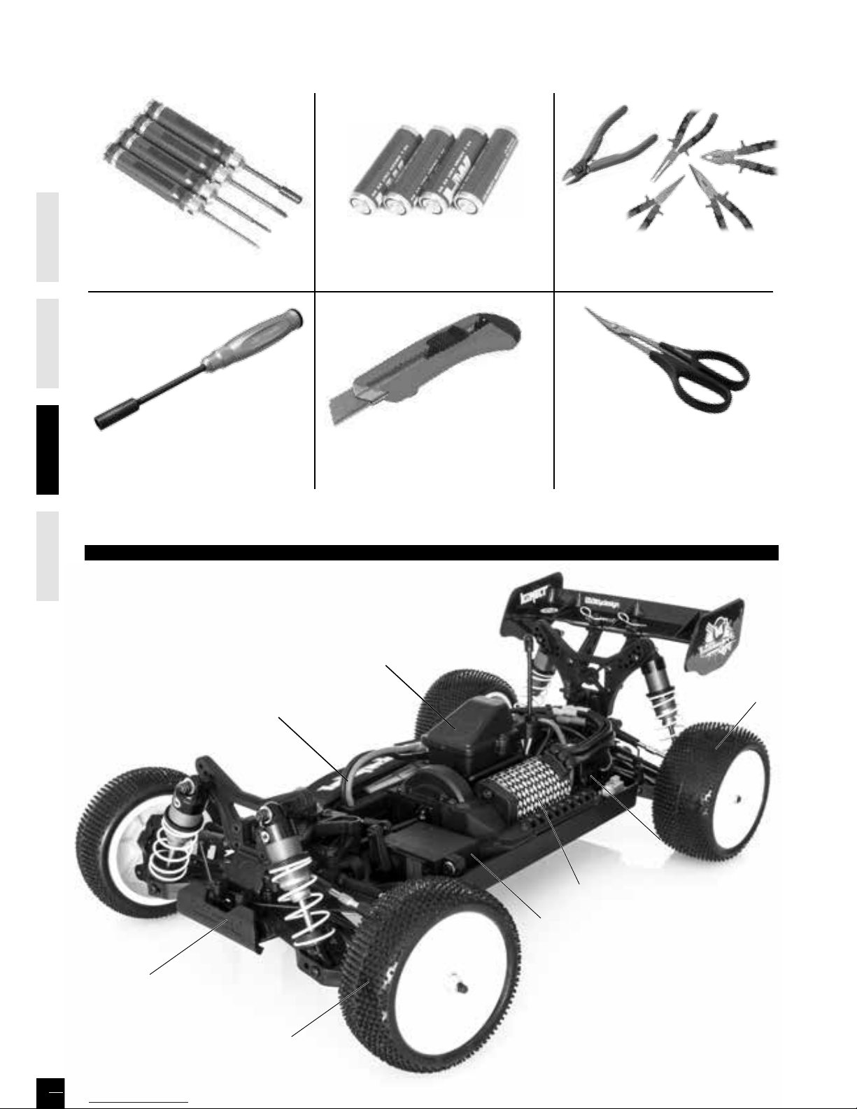
CHASSIS
ENGLISHFRAN
Ç
AISDEUTSCHESPAÑ OL
24
Gebogene Lexan Schere
EX 421200
4xAA Alkaline Batterien
BENÖTIGTE WERKZEUGE (NICHT IM LIEFERUMFANG ENTHALTEN!)
Multifunktions-Zangen Komplettset
Messer
HT 421910
1-10 Werkzeug-Set
1,5-2mm Inbusschlüssel
Philips 1.5mm
Steckschlüssel 5.5mm
EX 421932
Steckschlüssel 7mm
Akku
Box
Empfänger
Lenkservo
Geschwindig
-
keitsregler
Motor
Hinterreifen
Vorderreifen
Stoßstange
Funktionen
Batterie-LED-Anzeige
Batterieinstallation
Achtung: Zerlegen Sie niemals Batterien oder legen Sie diese ins Feuer
oder Chemikalien. Dies könnte zu Verletzungen oder Sachschäden führen.
Batterieentsorgung: Beachten Sie die entsprechenden Vorschriften zur
Behandlung und Entsorgung der verwendeten Batterien.
1. 1. Nachdem die Batterien leer sind, verwahren Sie diese korrekt auf, weit
weg von Wasserversorgung, Haushaltsbereichen und Pflanzflächen.
2. Bringen Sie die leere verwendeten Batterien zu spezifischen Recyclings-
tationen
Der Sender KT2S +
Lenkrad : Steuert die Lenkrichtung (links/rechts) des
RC-Modells
Gashebel : Regelt die Geschwindigkeit & Fahrtrichtung
(Vorwärts/Bremse/Rückwärts) des
RC-Modells
Antenne : Sendesignal zum RC-Modell
Power ON / OFF : Power AN / AUS des Senders
SYNC und Batterie-Anzeige : LED zeigt Synchonisationsstatus und / oder
den Status der Stromversorgung an
Betriebsanzeige : LED signalisiert Power "AN"
ATV : Zur Einstellung des max. Lenkweges
ST. Trim Einstellung : Zum justieren des Geradeauslauf bei
neutraler Lenkradstellung
TH. Trim Einstellung : Zum justieren der neutralen Gasstellung
Batteriefach : Abdeckung und Halterung der Batterien für
die Stromversorgung des Senders
BIND / EPA : Taste um Empfänger und Fernsteuerung zu
verbinden, sowie zum Einstellen der EPA
Funktion auf Kanal 1 & 2
WARNING: Versehentliches oder vorsätzliches falsches Einstellen der EPA
(End-Punkt-Einstellung) Funktion, kann zu einer Fehlfunktion oder
Beschädigung der Servos führen. Reduzieren Sie daher immer den
maximalen Ausschlag, um den nicht benötigten Servoweg. Bevor Sie sich
an den Fachhandel wenden, stellen Sie bitte wieder die maximalen
Standartwerte ein (Sieh Seite 27, «EPA»).
Arbeitet mit 4x 1,5V AA
Batterien oder Akkus (nicht
enthalten), die KT2S+ kann
damit mehrere Stunden
betrieben werden.
Installation: Entnehmen Sie die
Batteriefachabdeckung wie
unten dargestellt
Legen Sie die Batterien
oder Akkus ein, achten
Sie dabei auf die
richtige Polarität.
Dann installieren Sie
die Batteriefachab-
deckung wie im Bild
unten gezeigt.
- Im normalen Betrieb sollte die LED Anzeige grün leuchten
- Wenn die Batteriespannung unter 3.8V abfällt, leuchtet die LED rot und
blinkt sehr langsam. Dies zeigt an das die Batterien schwach sind und
umgehend durch neue ersetzt werden sollten.
Immer zuerst den Sender einschalten, indem Sie den Schalter von unten
nach oben schieben, die Leucht-Anzeige über dem Schalter ist jetzt grün.
Falls dies nicht der Fall ist, überprüfen Sie ob die Batterien entladen sind
oder falsch eingelegt wurden
1. Lenkung: Stellen Sie den Trimm so
ein, so dass die Vorderräder in einer
geraden Linie stehen und das Lenkrad
in NEUTRAL-Position ist.
2. Gas / Bremse: Stellen Sie die
Trimmung so ein, dass die Räder sich
nicht drehen wenn der Gashebel auf
Neutral steht (nur bei Verbrenner /
Nitro Fahrzeugen).
Bei Elektromodellen sollte die
Trimmung auf NEUTRAL stehen
(Sieh Seite 10, «1- Neutral-Punkt»).
Bevor Sie starten
LED
indicator
Indicator
LED
Batteriefach
ST. Trim Einstellung
Lenkrad
Gashebel
TH. Trim Einstellung
BIND/ EPA
Antenne
Betriebsanzeige
ATV
Power
ON / OFF
Umkehr Drehrichtung
Gas/Brems Servo
Umkehr Drehrichtung
Lenkservo
SENDER
BENUTZERHANDBUCH
Page 25

ENGLISHFRAN
Ç
AISDEUTSCHESPAÑ OL
25
Funktionen
Batterie-LED-Anzeige
Batterieinstallation
Achtung: Zerlegen Sie niemals Batterien oder legen Sie diese ins Feuer
oder Chemikalien. Dies könnte zu Verletzungen oder Sachschäden führen.
Batterieentsorgung: Beachten Sie die entsprechenden Vorschriften zur
Behandlung und Entsorgung der verwendeten Batterien.
1. 1. Nachdem die Batterien leer sind, verwahren Sie diese korrekt auf, weit
weg von Wasserversorgung, Haushaltsbereichen und Pflanzflächen.
2. Bringen Sie die leere verwendeten Batterien zu spezifischen Recyclings-
tationen
Der Sender KT2S +
Lenkrad : Steuert die Lenkrichtung (links/rechts) des
RC-Modells
Gashebel : Regelt die Geschwindigkeit & Fahrtrichtung
(Vorwärts/Bremse/Rückwärts) des
RC-Modells
Antenne : Sendesignal zum RC-Modell
Power ON / OFF : Power AN / AUS des Senders
SYNC und Batterie-Anzeige : LED zeigt Synchonisationsstatus und / oder
den Status der Stromversorgung an
Betriebsanzeige : LED signalisiert Power "AN"
ATV : Zur Einstellung des max. Lenkweges
ST. Trim Einstellung : Zum justieren des Geradeauslauf bei
neutraler Lenkradstellung
TH. Trim Einstellung : Zum justieren der neutralen Gasstellung
Batteriefach : Abdeckung und Halterung der Batterien für
die Stromversorgung des Senders
BIND / EPA : Taste um Empfänger und Fernsteuerung zu
verbinden, sowie zum Einstellen der EPA
Funktion auf Kanal 1 & 2
WARNING: Versehentliches oder vorsätzliches falsches Einstellen der EPA
(End-Punkt-Einstellung) Funktion, kann zu einer Fehlfunktion oder
Beschädigung der Servos führen. Reduzieren Sie daher immer den
maximalen Ausschlag, um den nicht benötigten Servoweg. Bevor Sie sich
an den Fachhandel wenden, stellen Sie bitte wieder die maximalen
Standartwerte ein (Sieh Seite 27, «EPA»).
Arbeitet mit 4x 1,5V AA
Batterien oder Akkus (nicht
enthalten), die KT2S+ kann
damit mehrere Stunden
betrieben werden.
Installation: Entnehmen Sie die
Batteriefachabdeckung wie
unten dargestellt
Legen Sie die Batterien
oder Akkus ein, achten
Sie dabei auf die
richtige Polarität.
Dann installieren Sie
die Batteriefachabdeckung wie im Bild
unten gezeigt.
- Im normalen Betrieb sollte die LED Anzeige grün leuchten
- Wenn die Batteriespannung unter 3.8V abfällt, leuchtet die LED rot und
blinkt sehr langsam. Dies zeigt an das die Batterien schwach sind und
umgehend durch neue ersetzt werden sollten.
Immer zuerst den Sender einschalten, indem Sie den Schalter von unten
nach oben schieben, die Leucht-Anzeige über dem Schalter ist jetzt grün.
Falls dies nicht der Fall ist, überprüfen Sie ob die Batterien entladen sind
oder falsch eingelegt wurden
1. Lenkung: Stellen Sie den Trimm so
ein, so dass die Vorderräder in einer
geraden Linie stehen und das Lenkrad
in NEUTRAL-Position ist.
2. Gas / Bremse: Stellen Sie die
Trimmung so ein, dass die Räder sich
nicht drehen wenn der Gashebel auf
Neutral steht (nur bei Verbrenner /
Nitro Fahrzeugen).
Bei Elektromodellen sollte die
Trimmung auf NEUTRAL stehen
(Sieh Seite 10, «1- Neutral-Punkt»).
Bevor Sie starten
LED
indicator
Indicator
LED
Batteriefach
ST. Trim Einstellung
Lenkrad
Gashebel
TH. Trim Einstellung
BIND/ EPA
Antenne
Betriebsanzeige
ATV
Power
ON / OFF
Umkehr Drehrichtung
Gas/Brems Servo
Umkehr Drehrichtung
Lenkservo
SENDER
BENUTZERHANDBUCH
Page 26

ENGLISHFRAN
Ç
AISDEUTSCHESPAÑ OL
26
Stellen Sie das Fahrzeug auf einen Block, so das die Räder den
Boden nicht berühren.
A
Verbinden Sie den Akku zum Regler. Fixieren Sie die Kabel
richtig mit dem kleinen vorgesehenen Nylon Wrap.
Vor der Inbetriebnahme überprüfen Sie das Signal von
Sender und Empfänger.
Stellen Sie sicher das der TH Trim auf neutral ist.
SCHALTEN SIE DEN SENDER UND EMPFÄNGER AUS
B
Drücken und halten Sie die Setup-Taste am Receiver beim
Einschalten des Receivers
C
.
Lassen Sie die Setup-Taste los, wenn das LED grün blinkt.
Während das LED grüne blinkt, drücken Sie die Setup-Taste, um
die Bildfrequenz zu wählen.
- Schnelles blinken = hohe Bildfrequenz (7 ms) für digital Servo
- Langsamere blinkt = niedriger Bildfrequenz (15 ms), für analog
Servo.
D
Drücken und halten Sie die Setup-Taste des Sender und
schalten Sie den Sender ein. Der Sender kommuniziert mit dem
RX. Wenn das RX-LED fest leuchtet, ist der Kopplungsprozess
ausgeführt, und das RX ist mit dem TX gekoppelt.
EINSCHALTEN DER STROMVERSORGUNG (BIND)
STEUERUNG IHRES MODELLS (1)
NEUTRAL POSITION
1. Drücken Sie den Gashebel nach vorne um zu bremsen/rückwärts zu fahren
2. Ziehen Sie den Gashebel nach hinten um Gas zu geben
BREMSE /
SENKGESCHWINDIGKEITSPOSITION
VORWÄRTS /
BESCHLEUNIGUNGSPOSITION
A
C
B
D
(1)
(2)
STEUERUNG IHRES MODELLS (2)
Wenn die Räder in die entgegengesetzten Richtung arbeiten, dann bedienen Sie den Servo- rückwärts-Schalter (ST in NOR Position).
NEUTRAL
LINKS RECHTS
Page 27

ENGLISHFRAN
Ç
AISDEUTSCHESPAÑ OL
27
Umkehr
DAS FUNKSYSTEM
1
2
4
5
3
Einschalten der Stromversorgung (BIND)
Trimmen
Einstellbarer max. Lenkausschlag (ATV)
Wird verwendet um die Bewegungsrichtung
der Lenkung oder von Gas & Bremse zu
ändern.
Die KT2S+ Fernsteuerung verfügt über 2
Umkehrfunktionen:
Lenkung und Gas /
Bremse / Rückwärts.
Umkehr Lenkung
: Sie lenken nach rechts
aber das Model fährt nach links - dann
stellen Sie diesen Schalter um.
Umkehr Gas / Bremse / Rückwärts
: Sie geben Gas aber das Model Bremst
oder fährt rückwärts - dann stellen Sie diesen Schalter um.
Deinen Empfänger mit der KT2S+ Fernsteuerung verbinden
1. Schalten Sie Fernsteuerung und Empfänger aus.
2. Drücken und halten Sie den BIND Knopf am Empfänger gedrückt und
schalten Sie diesen ein.
3. Lassen Sie den BIND Knopf los wen die LED rot blinkt.
4. Während die LED rot blinkt, können Sie die Frame Rate mit de
m BIND
Knopf verändern (kurzes drücken des Knopfes).
- Schnelleres blinken = höhere Frame Rate (7ms) / besser für di
gitale Servos
-
Langsameres blinken = niedrigere Frame rate (15ms) / besser für analoge Servos
5. Drücken und halten Sie anschließend den BIND/EPA Knopf an der
Fernsteuerung gedrückt. Schalten Sie dann parallel die Fernsteuerung an.
Die LED sollte nun grün blinken und die Fernsteuerung kommuniziert mit
dem Empfänger. Lassen Sie den BIND/EPA Knopf los wenn die LED des
Empfängers dauerhaft rot leuchtet und die LED der Fernsteuerung grün. Nun
ist der Empfänger mit der Fernsteuerung verbunden.
Mit dem einstellbaren Lenkausschlag können Sie den maximalen Lenkweg
nach Links und Rechts vorgeben den das Servo machen soll, wenn Sie das
Lenkrad der Fernsteuerung ganz einschlagen. Diese Funktion beeinflusst auch
die Empfindlichkeit des Servos, so kann ein reduzieren des max. Lenkweges
die Empfindlichkeit des Servos heruntersetzen. Mit der ATV Einstellung wird
der maximale Lenkausschlag nach links und rechts gleichermaßen verändert.
Beachten Sie den max. Lenkausschlag nur innerhalb des maximal möglichen
mechanischen Lenkweges einzustellen. Im Uhrzeigersinn = erhöhen des max.
Lenkweges; gegen den Uhrzeigersinn = reduzieren des max. Lenkweges.
Die minimale Einstellung = maximal gegen den Uhrzeigersinn bedeutet
NULL-Lenkwinkel.
Der KT2S verfügt über zwei Trimmfunktionen:
Lenktrimm und Gastrimm.
Lenktrimm Einstellung:
Steuert die Neutralstellung des Lenkservos. Bei
Neutraler Lenkradstellung sollen auch die Räder neutral (gerade
) stehen.
Im Betrieb sollte das RC-Modell bei neutraler Lenkradstellung g
eradeaus
fahren.
Normalerweise wird der Lenktrimm eingestellt, bis das Modell ge
rade
Strecken halten kann.
Lenktrimm Einstellung:
Steuert die Neutralstellung des Lenkservos. Bei
Neutraler Lenkradstellung sollen auch die Räder neutral (gerade
) stehen.
Im Betrieb sollte das RC-Modell bei neutraler Lenkradstellung g
eradeaus
fahren.
End Punkt Einstellung (EPA)
Um mechanischen Stress beim Lenken, Gas geben oder Bremsen (Nit
ro / Verbrenner) zu vermeiden, kann ein digitaler Endpunkt (EPA) für die Servos gesetzt
werden. Bei der ATV Funktion kann dies zwar auch für die Lenkun
g gemacht werden, aber nur Links & Rechts gleichermaßen. Mit der EPA Funktion können Sie
dies für Links & Rechts unabhängig voneinander einstellen.
Wenn Sie die EPA Funktion nutzen wollen lesen Sie die folgende Anleitung sorgfältig:
1. Lenkservo
a) Fernsteuerung und Empfänger einschalten (Grüne LED leuchtet)
, drehen Sie das Lenkrad maximal in die Richtung welche Sie einstellen wollen. Halten Sie nun
den BIND/EPA Knopf für 2 Sekunden gerückt, nun sollte die LED rot leuchten.
b) So lange die rote LED leuchtet, können Sie den maximalen Lenkweg auf der Seite wählen die Sie einstellen möchten.
Haben Sie den gewünschten Lenkwinkel ausgemacht, drücken Sie er
neut den BIND/EPA Knopf für 2 Sekunden. Die LED blinkt nun zwei Mal (hellgrün/dunkel
grün) und leuchtet anschließend dauerhaft grün
WICHTIG: Schalten Sie die Fernsteuerung Aus und wieder Ein, um die Einstellung zu bestätigen.
c) Um die Standardeinstellungen wiederherzustellen, folgen Sie
den Schritten a) und b). Drehen Sie das Lenkrad maximal nach Links bzw. Rechts und drücken
Sie dann für 2 Sekunden den BIND/EPA Knopf. Die LED blinkt nun
zwei Mal (hellgrün/dunkel grün) und leuchtet anschließend dauerhaft grün.
WICHTIG: Schalten Sie die Fernsteuerung Aus und wieder Ein, um die Einstellung zu bestätigen.
Um die andere Lenkrichtung einzustellen wiederholen Sie die Sch
ritte a) und b) nur eben in die gegengesetzte Richtung einlenken.
Es ist sehr wichtig, dass Sie diese Einstellung für beide Lenkrichtungen und nacheinander vornehmen, um Beschädigungen zu verme
iden.
2. Gas- & Bremsservo (EPA wird nur bei Verbrenner / Nitromodellen benötigt)
a) Fernsteuerung und Empfänger einschalten (Grüne LED leuchtet)
, halten Sie den Gashebel auf Vollgasstellung (max. gezogen). Halten Sie nun den BIND/EPA
Knopf für 2 Sekunden gerückt, nun sollte die LED rot leuchten.
b) So lange die rote LED leuchtet, können Sie den maximalen Gas
weg wählen den Sie benötigen bzw. einstellen möchten.
Haben Sie die gewünschte Position ausgemacht, drücken Sie erneu
t den BIND/EPA Knopf für 2 Sekunden. Die LED blinkt nun zwei Mal (hellgrün/dunkel grün) und
leuchtet anschließend dauerhaft grün
WICHTIG: Schalten Sie die Fernsteuerung Aus und wieder Ein, um die Einstellung zu bestätigen.
c) Um die Standardeinstellungen wiederherzustellen, folgen Sie
den Schritten a) und b). Bewegen Sie den Gashebel auf Vollgasstellung (max. gezogen) und
drücken Sie dann für 2 Sekunden den BIND/EPA Knopf. Die LED bli
nkt nun zwei Mal (hellgrün/dunkel grün) und leuchtet anschließend dauerhaft grün.
WICHTIG: Schalten Sie die Fernsteuerung Aus und wieder Ein, um die Einstellung zu bestätigen.
Um die maximale Bremskraft einzustellen wiederholen Sie die Sch
ritte a) und b) nur dieses Mal den Gashebel in die gegengesetzte Richtung bewegen (max. gedrückt).
Es ist sehr wichtig das Sie diese Einstellung für beide Richtungen und nacheinander vornehmen, um Beschädigungen zu vermeiden.
3
2
4
Page 28

ENGLISHFRAN
Ç
AISDEUTSCHESPAÑ OL
28
Hoch-Leistungssysteme für RC Modelle können sehr gefährlich sein, daher empfehlen wir Ihnen dringend diese Anleitung erst
sorgfältig durch zu lesen. Da wir keine Kontrolle über die korrekte Installation, Verwendung, Anwendung und / oder Wartung
unserer Produkte haben, übernehmen wir keine Haftung für Schäden, Verluste und / oder Kosten, die sich aus der fehlerhaften
Nutzung des Produktes ableiten. Etwaige Ansprüche von Versagen und Fehlfunktionen usw . des Betriebssystems werden
verweigert.
WIR ÜBERNEHMEN KEINE HAFTUNG FÜR PERSONENSCHÄDEN, SOWIE FOLGESCHÄDEN, DIE DURCH UNSER PRODUKT
ODER DEREN VERARBEITUNG ENTSTEHEN. SOWEIT GESETZLICH ZULÄSSIG, IST DIE PFLICHT DES WERTERSATZES AUF DEN
RECHNUNGSBETRAG DES BETROFFENEN PRODUKTS BEGRENZT.
EIGENSCHAFTEN
1. Kompatibel mit sensorlosen bürstenlosen Motor
2. Speziell für RC Auto und Truck entwickelt, mit ausgezeichneten Start-up-, Beschleunigungs- und Linearität Funktionen
3. 2 Betriebsarten für unterschiedliche Anwendungen («Racing»-Modus, «Allgemein»).
4. Proportionale ABS Bremsfunktion mit 4 Schritte der maximalen Leistungseinstellung, 8 Schritte der Bremskraftanpassung und 4
Schritte der anfänglichen Bremskrafteinstellung
5. 4 Start-Modi («Durchschlag») von «soft» bis «sehr aggressiv», die sich für die jeweilig verschiedene Chassis, Reifen und
Rennbahnen eignen
6. Mehrere Schutzfunktionen: Niederspannungsabschaltschutz für Lithium- oder Nickel Akku / Überhitzungsschutz / Gas
Signalverlust Schutz / Motor blockier Schutz
7. Einfache Programmierung durch Taster, alternativ kann der Regler über die Program Card oder die Program LCD Box
programmiert werden)
8. Staub- und spritzwassergeschützt.
TECHNISCHE DATEN
Modell KONECT 50AMP WP “by HOBBYWING”
Kont. / Burst Strom 50A / 300A
Widerstand 0.0010ohm
Verwendbare Autos
Verwendbarer bürstenloser Motor
Akku
4-9 Zellen Ni-xx (Ni-MH oder Ni-Cd)
2S LiPo 6 cells NiMH
On-road ≥ 8T O-road ≤ 11T
Motor 3650
On-road ≥ 11T O-road ≤ 14T
Motor 3650
3S LiPo 9 cells NiMH
2-3 Zellen Li-Po
BEC Ausgang 6V / 2A
Motor Typ Sensorloser bürstenloser Motor
Abmessung & Gewicht 48,5x38x32 & 90g
BEGINNEN, UM DEN NEUEN
GESCHWINDIGKEITSREGLER ZU VERWENDEN
WARNUNG! DIESES BÜRSTENLOSE SYSTEM IST SEHR
KRÄFTIG! AUS SICHERHEITSGRÜNDEN SOLLTEN SIE DIE
RÄDER IMMER ABSEITS DER STRECKE HALTEN, WENN SIE DEN
GESCHWINDIGKEITSREGLER KNOPF BETÄTIGEN H
1. Verbinden Sie den Regler, Motor, Empfänger, Akku und
Servo nach dem folgenden Schema
Die # A, # B, # C Drähte des Reglers können frei mit den
Motordrähten (ohne Reihenfolge) angeschlossen werden.
Wenn der Motor in die entgegen gesetzte Richtung läuft,
tauschen Sie bitte zwei Kabelanschlüsse.
2. Gasbereich Einstellung (Gasbereich Kalibrierung)
Bei der ersten Inbetriebnahme muss der Regler zunächst an den
Gasweg des Senders angepasst werden. Stellen Sie am Sender
die Trimmung auf neutral und setzen Sie alle Einstellungen
wie ATV oder EPA auf 100%. Bei der Kalibrierung müssen drei
Punkte bestimmt werden:
• Vollgas-Position für vorwärts
• Vollgas-Position für rückwärts
• Neutralpunkt für Leerlauf (Aus)
A) Regler ausschalten, Sender einschalten und die Laufrichtung
des Gas-Kanals am Sender auf Reverse stellen, die Werte für
EPA & ATV auf 100% setzen. Sollte der Sender über eine ABSFunktion verfügen, muss(!) diese ausgeschaltet sein.
B) SET-Taster am Regler drücken und gedrückt halten,
gleichzeitig den Regler einschalten. Danach den SET-Taster
SOFORT loslassen, sobald die rote LED blinkt (Hi
nweis 4):
BEDIENUNGSANLEITUNG KONECT 50A WASSERFEST
Hinweis 4: Wenn Sie die „SET“ Taste nicht loslassen, sobald das rote LED Licht anfängt zu blinken, wird der Regler den Programm
Modus eingeben. In diesen Fall schalten Sie den Geschwindigkeitsregler aus und kalibrieren Sie die Gaseinstellung erneut – Punkt A)
C) Nun werden die drei Punkte gespeichert:
1) Neutral-Punkt:
Gashebel in die Neutral-Position bewegen und
gleichzeitig einmal den SETTaster drücken, die grüne
LED blinkt einmal.
2) Vollgas-Vorwärts-Punkt:
Gashebel in die Vollgas-Vorwärts-Position bewegen
und gleichzeitig einmal den SET-Taster drücken, die
grüne LED blinkt zweimal.
3) Vollgas-Rückwärts-Punkt:
Gashebel in die Vollgas-Rückwärts-Position
bewegen und gleichzeitig einmal den SET-Taster
drücken, die grüne LED blinkt dreimal.
D) Der Gasweg ist nun kalibriert, nach drei Sekunden ist der
Regler jetzt scharf geschaltet!
3. Status der LED
1) Wenn der Gashebel in Leerlaufposition steht, sind beide LEDs aus
2) Die rote LED leuchtet, wenn der Motor sich vorwärts oder rückwärts dreht, während des Bremsens blinkt die LED
3) Die grüne LED leuchtet auf, wenn der Gashebel in die Vollgas-Position für vorwärts/rückwärts bewegt wird
SIGNAL TÖNE
1. Eingangsspannung abnormaler Alarm Ton: Der Regler überprüft die Eingangsspannung, sobald dieser an ist. Wenn die
Spannung außerhalb des normalen Bereichs liegt, wird ein Alarm Ton hörbar: «piep-piep-, piep-piep-, piep-piep-» (Es gibt
einen Intervall zwischen jeden «piep-piep-» Ton).
2. Gas-Signal abnormaler Warnton: Wenn der Regler das normale Gas Signal nicht erkennen kann, wird ein Alarmton erklingen :
«piep-, piep-, piep-» (Es ist ein 2 Sekunden Intervall zwischen jedem «beep-» Ton).
SCHUTZFUNKTIONEN
1. Niedrigspannungsabschaltungsschutz: Wenn die Spannung des LiPo Packs niedriger ist als der Schwellenwert für 2 Sekunden,
dann wird die Ausgangsleistung abgeschaltet. Bitte beachten Sie das der Regler nicht erneut starten kann, wenn die Spannung
jeder LiPo Zelle niedriger ist als 3.5V.
Für NiMH Akkus gilt; wenn die Spannung des gesamten NiMH Packs höher ist als 9.0V aber niedriger als 12V dann wird er erkannt
als 3S LiPo. Ist Die Spannung niedriger als 0.9V steht er gleich an ein 2S LiPo. Wenn Zum Beispiel der NiMH Akku 0.8V hat und
der Schwellenwert ist eingestellt auf 2.6V/Zelle, wird er als 2S LiPo erkannt und die Niedrigspannungsabschaltschwelle für diesen
NiMH Akkus ist 2.6 x 2 = 5.2V
2. Überhitzungsschutz: Wenn diese Funktion aktiviert ist, wird die Ausgangsleistung abgeschnitten, sobald die Temperatur des
Reglers höher ist, als der vorprogrammierte Werkseinstellungswert für 5 Sekunden. Sie können diese Schutzfunktion der
Überhitzung für Wettrennen deaktivieren.
3. Gas-Signal Verlust Schutz: Der Regler unterbricht die Ausgangsleistung, wenn das Gas-Signal für 0,2 Sekunden verloren ist.
FEHLERSUCHE
PROBLEM MÖGLICHE URSACHE LÖSUNG
Keine Reaktion nach dem Anschluss des Akkus.
Schlechter Kontakt der Steckerverbindungen. Steckerverbindungen prüfen und ggf. erneuern.
Nach dem Anschluss des Akkus sendet
der Motor ein Beep-Beep- Signal in einem
Intervall von einer Sekunde.
Die Akkuspannung ist zu hoch oder zu niedrig
Überprüfen Sie die Akkuspannung und verwenden Sie ggf.
einen zulässigen Akku.
Nach dem Anschluss des Akkus sendet der
Motor ein Beep-Signal in einem Intervall von
zwei Sekunden.
Der Regler erkennt kein Sendersignal.
Geringe Reichweite der RCAnlage, Empfängerkabel des
Reglers defekt.
Der Motor dreht sich in der falschen
Richtung.
Motor falsch mit dem Regler verbunden. Zwei beliebige Motorkabel am Regler umpolen
Der Motor bleibt im Betrieb einfach stehen.
Der Unterspannungsschutz oder der
Temperaturschutz im Regler ist aktiv oder es ist
kein Sendersignal vorhanden.
Betrieb einstellen und Akku erneut aufladen bzw. Temperatur
des Reglers / Motors prüfen. Reichweite der RC-Anlage prüfen.
Beim Gasgeben fängt der Motor an zu
ruckeln.
Falsche Getriebeübersetzung
Zu schwacher Akku
Zu hoher Level im Start Mode gewählt
Kleineres Ritzel verwenden.
Akku laden, bzw. austauschen.
Niedrigeren Level im Regler-Setup wählen.
Page 29

ENGLISHFRAN
Ç
AISDEUTSCHESPAÑ OL
29
Hinweis 4: Wenn Sie die „SET“ Taste nicht loslassen, sobald das rote LED Licht anfängt zu blinken, wird der Regler den Programm
Modus eingeben. In diesen Fall schalten Sie den Geschwindigkeitsregler aus und kalibrieren Sie die Gaseinstellung erneut – Punkt A)
C) Nun werden die drei Punkte gespeichert:
1) Neutral-Punkt:
Gashebel in die Neutral-Position bewegen und
gleichzeitig einmal den SETTaster drücken, die grüne
LED blinkt einmal.
2) Vollgas-Vorwärts-Punkt:
Gashebel in die Vollgas-Vorwärts-Position bewegen
und gleichzeitig einmal den SET-Taster drücken, die
grüne LED blinkt zweimal.
3) Vollgas-Rückwärts-Punkt:
Gashebel in die Vollgas-Rückwärts-Position
bewegen und gleichzeitig einmal den SET-Taster
drücken, die grüne LED blinkt dreimal.
D) Der Gasweg ist nun kalibriert, nach drei Sekunden ist der
Regler jetzt scharf geschaltet!
3. Status der LED
1) Wenn der Gashebel in Leerlaufposition steht, sind beide LEDs aus
2) Die rote LED leuchtet, wenn der Motor sich vorwärts oder rückwärts dreht, während des Bremsens blinkt die LED
3) Die grüne LED leuchtet auf, wenn der Gashebel in die Vollgas-Position für vorwärts/rückwärts bewegt wird
SIGNAL TÖNE
1. Eingangsspannung abnormaler Alarm Ton: Der Regler überprüft die Eingangsspannung, sobald dieser an ist. Wenn die
Spannung außerhalb des normalen Bereichs liegt, wird ein Alarm Ton hörbar: «piep-piep-, piep-piep-, piep-piep-» (Es gibt
einen Intervall zwischen jeden «piep-piep-» Ton).
2. Gas-Signal abnormaler Warnton: Wenn der Regler das normale Gas Signal nicht erkennen kann, wird ein Alarmton erklingen :
«piep-, piep-, piep-» (Es ist ein 2 Sekunden Intervall zwischen jedem «beep-» Ton).
SCHUTZFUNKTIONEN
1. Niedrigspannungsabschaltungsschutz: Wenn die Spannung des LiPo Packs niedriger ist als der Schwellenwert für 2 Sekunden,
dann wird die Ausgangsleistung abgeschaltet. Bitte beachten Sie das der Regler nicht erneut starten kann, wenn die Spannung
jeder LiPo Zelle niedriger ist als 3.5V.
Für NiMH Akkus gilt; wenn die Spannung des gesamten NiMH Packs höher ist als 9.0V aber niedriger als 12V dann wird er erkannt
als 3S LiPo. Ist Die Spannung niedriger als 0.9V steht er gleich an ein 2S LiPo. Wenn Zum Beispiel der NiMH Akku 0.8V hat und
der Schwellenwert ist eingestellt auf 2.6V/Zelle, wird er als 2S LiPo erkannt und die Niedrigspannungsabschaltschwelle für diesen
NiMH Akkus ist 2.6 x 2 = 5.2V
2. Überhitzungsschutz: Wenn diese Funktion aktiviert ist, wird die Ausgangsleistung abgeschnitten, sobald die Temperatur des
Reglers höher ist, als der vorprogrammierte Werkseinstellungswert für 5 Sekunden. Sie können diese Schutzfunktion der
Überhitzung für Wettrennen deaktivieren.
3. Gas-Signal Verlust Schutz: Der Regler unterbricht die Ausgangsleistung, wenn das Gas-Signal für 0,2 Sekunden verloren ist.
FEHLERSUCHE
PROBLEM MÖGLICHE URSACHE LÖSUNG
Keine Reaktion nach dem Anschluss des Akkus.
Schlechter Kontakt der Steckerverbindungen. Steckerverbindungen prüfen und ggf. erneuern.
Nach dem Anschluss des Akkus sendet
der Motor ein Beep-Beep- Signal in einem
Intervall von einer Sekunde.
Die Akkuspannung ist zu hoch oder zu niedrig
Überprüfen Sie die Akkuspannung und verwenden Sie ggf.
einen zulässigen Akku.
Nach dem Anschluss des Akkus sendet der
Motor ein Beep-Signal in einem Intervall von
zwei Sekunden.
Der Regler erkennt kein Sendersignal.
Geringe Reichweite der RCAnlage, Empfängerkabel des
Reglers defekt.
Der Motor dreht sich in der falschen
Richtung.
Motor falsch mit dem Regler verbunden. Zwei beliebige Motorkabel am Regler umpolen
Der Motor bleibt im Betrieb einfach stehen.
Der Unterspannungsschutz oder der
Temperaturschutz im Regler ist aktiv oder es ist
kein Sendersignal vorhanden.
Betrieb einstellen und Akku erneut aufladen bzw. Temperatur
des Reglers / Motors prüfen. Reichweite der RC-Anlage prüfen.
Beim Gasgeben fängt der Motor an zu
ruckeln.
Falsche Getriebeübersetzung
Zu schwacher Akku
Zu hoher Level im Start Mode gewählt
Kleineres Ritzel verwenden.
Akku laden, bzw. austauschen.
Niedrigeren Level im Regler-Setup wählen.
Page 30

ENGLISHFRAN
Ç
AISDEUTSCHESPAÑ OL
30
PROGRAMMIEREN DES GESCHWINDIGKEITSREGLERS
1. Programmier Methode
Hinweis 5: • Im Programmablauf wird der Motor «Piep»-Ton gleichzeitig emittiert, wenn das LED blinkt.
• Wenn das «N» größer ist als die Zahl «5», wird ein Langzeit Blinken und ein langer «Piep»-Ton verwendet. So ist es
einfach, die Positionen der großen Zahl zu identifizieren.
Zum Beispiel, wenn das LED wie folgt blinkt:
«Ein Langzeit Blinken + Kurzzeit Blinken « (Motor klingt «Piep---Piep») = die Nr. 6
«Ein Langzeit Blinken + 2 Kurzzeit Blinken» (Motor klingt «Piep --- PiepPiep») = die Nr. 7
«Ein Langzeit Blinken + 3 Kurzzeit Blinken» (Motor klingt «Piep --- PiepPiepPiep») = die Nr. 8 ... Und so weiter !
Programmierbare Positionen
(Der kursive Text in der Auflistung stellen die Standardeinstellungen dar)
1 2 3 4 5 6 7 8
1. Running Mode
Forward Only
with Brake
Forward/Reverse
with Brake
2. Drag Brake Force
3. Low Voltage
Cut-Off Threshold
Non-Protection 2.6V/Cell 2.8V/Cell
3.2V
/Cell
3.4V
/Cell
4. Start Mode (Punch) Level1 Level2
5. Max Brake Force 25%
9
Programmable
Items
Basic Items
Programmable Value
3.0V
/Cell
10% 20% 40% 60% 80% 100%
100%
5%
Level4
Level3
75%
0%
50%
Page 31

ENGLISHFRAN
Ç
AISDEUTSCHESPAÑ OL
31
2. Programmierbare Werte
2.1. Fahrmodus: Mit «Vorwärts mit Bremse» Modus, kann das Auto vorwärts fahren und bremsen. Es kann nicht rückwärts fahren,
dieser Modus eignet sich für den Wettbewerb. Der «Vorwärts / Rückwärts mit Bremse» Modus bietet auch die rückwärts Funktion
die sich für das tägliche Training eignet.
Hinweis: Der «Vorwärts / Rückwärts mit Bremse» Modus verwendet eine «Double-Click» Methode, um das Auto rückwärts zu
bewegen. Wenn Sie den Gashebel von der vorwärts Zone auf die rückwärts Zone bewegen (1.»Klick»), wird der Regler den Motor
abbremsen und die Beschleunigung abdrosseln, jedoch nicht vollständig stoppen. So passiert die Rückwärtsaktion nicht sofort.
Wenn der Gashebel erneut auf der rückwärtigen Zone bewegt wird (2. «Klick»), wird die Motordrehzahl wird auf Null gedrosselt (d.h.
gestoppt) . Die rückwärts Handhabung kann beginnen. Die «2-fach (Double-Click)» Methode kann eine fälschlicherweise rückwärts
Funktion verhindern, wenn die Bremsfunktion für das Fahren häufig verwendet wird.
2.2. Bremskraftverteilung:
Bürsten Motors im Freilauf zu simulieren.
2.3. Niedrigspannungsabschaltung: Die Funktion verhindert, dass die Lithium-Batterie zu niedrig entladen wird. Der
Geschwindigkeitsregler erfasst die Spannung der Batterie zu jedem Zeitpunkt. Wenn die Spannung niedriger ist als der Schwellenwert
für 2 Sekunden, dann wird die Ausgangsleistung abgeschaltet und das rote LED blinkt so: «❏-❏-,❏-❏-,❏-❏-».
Verwendung einer LCD Programmierkarte (als Option erhältlich) mit einem Schritt von 0.1V anpassen. So wird es besser geeignet
sein für alle Arten von Batterien (Ni-MH, Ni-Cd, Li-Ion, Lipo, LFP, etc). Bitte beachten Sie das die angepassten Werte nicht für eine
einzelne Zellen gelten, sondern für das GANZE AKKU PACK !
2.4. Start Modus («Punch»):
während «Niveau 4» eine sehr aggressive Start Wirkung aufweist. Die Start Kraft ist von «Niveau 1» bis hin zu «Niveau 4» zunehmend.
2.5. Maximale Bremskraftverteilung: Der Geschwindigkeitsregler bietet proportionale Bremsfunktion. Die Bremskraft ist mit der
Position des Gashebels verbunden. Die maximale Bremskraft bezieht sich auf die Kraft, wenn der Gashebel am Toppunkt der
rückwärts Zone liegt. Eine sehr große Bremskraft kann die Bremszeit verkürzen, aber auch die Zahnräder beschädigen.
3. Zurücksetzen aller Elemente auf die Standardwerte
Zu jeder Zeit, wenn die Drosselklappe sich in neutraler Zone befindet (außer in Gaskalibrierung oder Parameter Programm-Prozess).
Halten Sie die «SET» Taste länger als 3 Sekunden, sobald das rote und grüne LED gleichzeitig blinken, wurde jedes programmierbare
Element auf den Standardwert zurückgesetzt.
OPTIONALES ZUBEHÖR
1. Kühl Ventilator (12V)
Die Hochspannungs-Ventilator ist notwendig, wenn Sie 3S LiPo oder Ni-MH-Akku mit mehr als 6 Zellen verwenden.
WARNUNG! Bitte beachten Sie das ausschließlich nur der Original-Lüfter (5V) empfohlen wird, um mit 2S LiPo oder 4-6 Zellen NiMH-Batterie zu arbeiten. Bitte verwenden Sie diesen NICHT mit einem 3S LiPo oder Ni-MH-Akku mit mehr als 6 Zellen.
Bitte überprüfen Sie das Etikett des Lüfters sorgfältig auf seine Betriebsspannung, bevor Sie diesen bestätigen.
2. LED Programmierkarte
Die Programm Karte ist ein optionales Zubehör, das separat erworben werden kann. Es verfügt
üb
er eine benutzerfreundliche Oberfläche. Das Verfahren der Reglerprogrammierung wird ganz
einfach und schnell mit diesen Taschenformat Gerät. Wenn der programmierbare Wert geändert
werden muss, schließen Sie bitte einfach die Steuerleitungen des Geschwindigkeitsregler (3
Drähte mit schwarzer, roter und weißer Farbe) in die Buchse der Programm Karte. (Die Buchse
ist an der rechten Ecke und mit
markiert). Schließen Sie dann den Haupt-Akku an den
Regler an. Nach einigen Sekunden wird jeder einzelne Wert auf dem Programm Karte angezeigt.
Verwenden Sie die «ITEM» und «VALUE» Taste, um die programmierbaren Elemente und neuen
Werte zu selektieren. Drücken Sie dann die «OK» Taste, um die neuen Einstellungen in dem
Geschwindigkeitsregler zu speichern.
• Der Programmanschluss ist mit dem Lüfter Anschluss Multiplex, bitte trennen
Sie erst den Lüfter, und verwenden Sie dann das Programm-Kabel, um den
Lüfter-Anschluss des Reglers an die LED-Programm-Karte anzuschließen.
Item # KN-PROGRAM-CARD
Page 32
GARANTIA DE 90 DIAS
LEER CON MUCHA ATENCION LAS LINAS SIGUIENTES :
La garantia de 90 dias empieza el dia de la compra del producto Durante esta temporada de 90 dias la garantia cubre todos los
componentes (menos las pezas de transmicion)Si un componente no funciona despues de ser averiguade por nuestro servicio
tecnico sera cambiado.
Este producto no es un juguete los menores de 14 anos tienen que utilizarlo bajo la responsabilidad de adultos.
Cuando se utiliza el producto si hay un problema hay que areglarlo inmediatamente.
SIN GARANTIA
Este producto es un modelo de halta prestacion, y se tratara de utilizarlo con cuidado y respeto.Al nivel del concepto se
escojieron pructos robustos . Sin enbargo si se utiliza el pructo de una manera muy dura se pueden romper piezas.
La garantia no cubre piezas usadas o rotas por mal tratamiento La garantia tambien no cubre avarias por casos externos
al producto (por exemplo un accidente,golpes humedad ) y de una mala ulizacion (conectores enchufados al reves piezas
desmontadas por el utilizador o mal montadas .
COMO UTILIZAR LA GARANTIA
Si hay un problema tecnico la primera cosa es de consultar la persona que le vendio el producto por ejemplo su tienda habitual
de modelismo y le diran si su producto esta vajo garantia.
Nunca hay que mandar el producto al fabricante se tiene que presentar en primero a donde se compro.
De esta manera si se averigua que el producto tiene un problema tecnico y que la garantia lo cubre, el vendedor podra cambiar
la pieza defectuosa o mandar el producto directamente a nuestros amlmacenes..
Cuidado si no se respetan estas condiciones se facturara la mano de obra, las piezas defectuosas y los portes
Les aconsejamos guardar siempre las facturas de compras
ATENCION :
• Este coche no es un juguete. El comprador de este producto reconoce y comprende que asume la responsabilidad sobre los
danos personales o materiales que pueda causar por El uso de este producto.
• El usuario es el unico responsable del correcto uso de este producto. El fabricante o el vendedor no tienen ninguna
responsabilidad sobre los posibles danos producidos por su mal uso.
• No use el coche R/C en lugares peligrosos donde pueda causar danos a personas o propiedades.
• No deje su coche y emisora a la intemperie. La humedad de la noche puede causarles danos.
• No olvide retirar las pilas y/o emisora si no va a utilizarlos mas en el dia.
• No use pilas o baterias mezcladas de diferentes tipos o antiguedad.
• Asegurese de apagar la emisora cuando vaya a dejarla de sus manos. Si esta encendida, se pueden mover los controles
involuntariamente y causar un accidente.
• Mantenga el coche fuera del alcance de los ninos. Este aparato esta pensado para personas mayores de 14 anos. Los
menores de esta edad deberan usarlo siempre bajo la supervision de un adulto.
DECLARACION DE CONFORMIDAD SEGUN LA DIRECTIVA R&TTE 1999/05/CE
Sarl Imodel
5 place de Rome
13006 Marseille
France
Declara que el producto siguiente: BXRS1
w/ KONECT KT2S+ Transmitter & Receiver
Item Number: 1.BXR.S1.RTR
Catégoria de equipo : 1
Coresponde a las exigencias oficiales de la directiva FTEG (Articulo 3 de la directiva R&TTE)
• Proteccion de la salud y de la securidad del usuario o de toda otra personaen
conformidad con el articulo 3.1.a
Norma aplicada : EN 62311:2008
• Exigencias en materia de proteccion segun la compatibilidad electromanetica
(articulo 3.1b)
Norma aplicada : EN 301 489-1 V1.9.2 (2011-09)
EN 301 489-3 V1.4.1 (2002-08)
• Utilizacion del spectro aplicado a las comunicaciones radioterestres o espaciales y eficaz y
al recourso orbital para evitar las interferencias peligrosas (articulo 3.2).
Normes appliquées: EN 300 440-1 V1.6.1 (2010-08)
EN 300 440-1 V1.4.1 (2010-08)
Direccion del fabricante : Sarl Imodel
5 place de Rome
13006 Marseille
France
Fecha 27 de Septiembre 2012
Esta pictografia enseina que el producto no debe ser tratado
como restos caseros Tienen que eliminar esto productosafin sin
danar a la salud y al medioambiente. Un tratamiento sin control
de este produto podria concecuencias negativas sobre el medio
ambiente y la salud. ayudenos a respetar el medio ambiente
i.A.
ENGLISHFRAN
Ç
AISDEUTSCHESPAÑ OL
32
Page 33

IMPORTANTE LEER ANTES DE ARRANCAR
LEER ESTAS INSTRUCCIONES Y ACOSTUMBRARSE CON LOS PRODUCTOS ANTES DE UTILIZARLOS.
Este producto no es un juguete es un modele reduzido y hay que aprender poco a poco bajo los consejos de un adulto.
CUIDADO
Antes de danar a personas o a objetos utilizar el modelo teledirigido de manera responsable como esta detaillado mas lejos
Estos modelos pueden alcanzar una velocidad de mas de 40KM/H.
❶ Nunca conducir el modelo en carreteras y en la caille porque podrian provocar accidentes
❷ No hay que rodar cerca de personas o de animales.
❸ Para no danar a personas o animales no hay que rodar en sitios demaciados pequenos
❹ Manejar con el modelo en la casa puede danar a objetos.
PRECAUCIONES DE UTILIZACION
Cuando el modelo esta en marcha nunca hay que tocar las piezas en movimiento (transmicion ruedas engrenage).
❶ Cuando el coche esta rodando el motor se calienta y puede llegar a una alta temperatura no hay que tocarlo. Sino hay
riesgo de quemaduras.
❷ Proteger todos los cables electricos que no sean en contacto con pieza en movimiento sostener los cables con collares de
plastico sujetados al chasi del coche.
❸ El motor puede estropearse si todas las piezas en movimiento no estan libres :ruedas,ejes de transmicion pignones. El motor
puede calentarse demaciafdo y gastara mas baterias.
❺ Si la bateria se descarga y no puede alimentar el receptor el coche empieza a perder velocidad hay que cargar
inmediatamente la bateria
CONSIGNAS DE SEGURIDADES
- No hay que utizar el modelo en el medio de ninos o de la muchedumbre
- No hay que rodar el el agua o bajo la lluvia Si el motor o la electronica esta mojada hay que secarla.
Puesta en marcha de la Radio:
❶ Encender la emisora despues de haber puesto el Trim (motor) a la posicion 0
❷ Enchufar en posicion on el receptor
❸ Antes de rodar averiguar coche parado que todos los mandos uncionan
❹ Ajustar el trim del volante para que el coche rode derecho
❺ Despues de rodar para parar el mando primero apagar el receptor y despues la emisora
❻ Desenchufar la bateria
❼ Y antes de todo limpiar el modelo
Para aumentar las prestaciones del modelo es necesario de ajustar el coche segun el tipo de circuito .
Las ruedas : utizar el tipo de ruedas segun el circuito : arena,tiera, asfalto.
ENGLISHFRAN
Ç
AISDEUTSCHESPAÑ OL
33
Page 34

ENGLISHFRAN
Ç
AISDEUTSCHESPAÑ OL
34
LEER CUIDADOSAMENTE ESTE MANUAL DE INSTRUCCIONES ANTES DE COMENZAR EL RODAJE :
Volante de direccion : Controla la direccion (izquierda/derecha)
del modelo
Gastillo de los gases : Controla la velocidad y la direccion
(Marcha adelantera / Freno / Marcha atras)
del modelo
Antena : Transmite el senal al modelo
Power ON / OFF : Encender / parar la emisora
SYNC & Battery Indicator : La Led verde indica el estatuto de
sincronisacion y/o la potencia de la bateria.
ATV : Adjustable Steering Rate by ATV dial
ST. Trim : Ajusta la posicion neutral del servo de
direccion cuando la ruedas son rectas
TH. Trim : Para que el modelo no se mueva
cuando el gastillo esta al neutral
Compartimiento de la baterias : Cubre y mantiene la baterias
FUNCIONES DE LA EMISORA KT2S+
Compartimiento de la baterias
Trim de direccion
Volante de
direccion
Gastillo de
los gases
Trim
gas / freno
BIND /
EPA
Antena
Indicador
de marcha
A
TV
Power
ON / OFF
Inversion
gas/freno
Inversion
direccion
Cuando cargue, por
favor pongar el pruducto
en lugar fresco y seco,
alejado de fuentes de
calor o explosivas
Cuando cargue, quite la baterias del
drone. La carga ha de ser superfisada
por un adulto, para evitar accidentes.
Despues de vuelo, no carguer la bateria
si esta caliente, de otro modo podria
causar danos o fuego en la bateria.
Asegurarse de que esta usando el
cargadore o USB suministrado. Si la
bateria no ha usada por mucho o
parece danada, por favor cambiala.
Una bateria sin usar mucho tiempo
se pierde la carga automaticamente.
La carga y la descarga continuada
reduce la vida de la bateria.
INSTALACION BATERIAS DE EMISORA
❶ Retire la tapa
❷ Instale 4 pilas alcalinas
AA tal y como muestra
el dibujo
❸ Cierre la tapa y
coloquela en su lugar
INDICADOR LED NIVEL DE BATERIA
ANTES DE EMPEZAR
- Durante una operacion normal, la LED verde se queda encendida.
- Cuando la tension bajo 3.8V, la LED se vuelve roja y parpadea lentamente. Cambiar las baterias urgentemente.
1. Steering : Ajustar el Trim de direccion para quedar la ruedas delanteras rectas cuando el volante
de direccion de la emisora esta en posicion neutral.
2. Throttle : Ajustar el Trim de gaz y freno para asegurarse que las ruedas se paran cuando el
gatillo de la emisora esta en posicion neutral (solamente para coches con motor termico).
Para coches electricos, este boton debe ser areglado en modo neutral (ver «1-Punto neutro»,
pagina 38).
* Siempre encender la emisora de primero con el interuptor «ON/OFF». La Led verde aparece.
Si no aparece, tienen que verificar la posicion de les baterias de la emisora o cambiar la baterias.
Indicateur LED de batterie
Compartiment
porte-piles
ST.TRIM :
Trim de direction
Volant de
direction
Gâchette des gaz
TH.TRIM :
Trim gaz/frein
BIND (Synchronisation) /
EPA (Ajustement fin de course)
Antenne
Indicateur
de marche
ATV
POWER
ON / OFF
TH N-R :
Inversion gaz/frein
ST N-R :
Inversion de direction
- Pendant une opération normale, la LED verte est allumée.
- Lorsque la tension descend sous 3.8V, la LED clignotera alternativement
Vert/Orange, pour indiquer que la batterie est faible. Remplacer les piles dès
que possible. ATTENTION : une batterie faible peut entraîner un dysfonction-
nement du véhicule.
1. Direction : Ajuster le Trim de direction
pour garder les roues avant en ligne
droite lorsque le volant de direction reste
en position neutre.
2. Gaz / Frein : Ajuster le Trim des gaz
pour s’assurer que les roues arrêtent de
tourner lorsque la gâchette des gaz reste
en position neutre (uniquement
thermique). Pour les véhicules
électriques, la position de la molette doit
être au neutre (voir «1-La position
Vérification avant la mise en route
LED
indicator
LED
indicateur
distribué par
Page 35

ENGLISHFRAN
Ç
AISDEUTSCHESPAÑ OL
35
Emparejar el emisor con el receptor. (el emparejamiento ya
esta efectuado en fabrica).
A
Conectar las baterias LiPo al variador.
Asegurarse que todos los componentes electronicos y
cables estan instalados correctamente..
Asegurarse de la buena sincronización de la emisora y del
receptor antes de su primera utilizacion.
Aseugurarse que el “Trim TH” esta puesto es posicion neutral.
DESCONECTAR LA EMISORA
B
Pulse el boton «BIND» del receptor al mismo tiempo
encender el interuptor del variador
C
.
Liberar el boton «BIND» cuando la LED se parpade en rojo.
Cuando la LED se parpade en rojo, pulsar el boton «BIND»
de la emisora para elijir la frequencia. Si no estan seguro del
tipo de servo que utilizan (digital o analogico), elijir la frequencia
parpadea lenta.
CUIDADO: No seleccionar la frequencia rapida para un servo
analogico, podria causar dano al servo
- Parpadea rapida = frequencia rapida (7ms), para servo digital
- Parpadea lenta = frequencia lenta (15ms), para servo analogico
Encender el interuptor del variador
D
Quedar el boton «BIND» pulsado de la emisora (1), y
encender la emisora (2), ahora se comunica con el receptor.
Cuando el LED se quede encendido,
el emarejamiento se ha completado
SINCRONISACION EMISORA / RECEPTOR (BIND)
COMPROBACION DE LA DIRECCION
NEUTRAL
IZQUIERDA DERECHA
Muevar el volante de la emisora para verificar que se mueve de forma corecta
NEUTRAL
FRENO / DECELERACION /
MARCHA ATRAS
ACELERACION /
MARCHA DELANTERA
A
C
B
D
(1)
(2)
Page 36
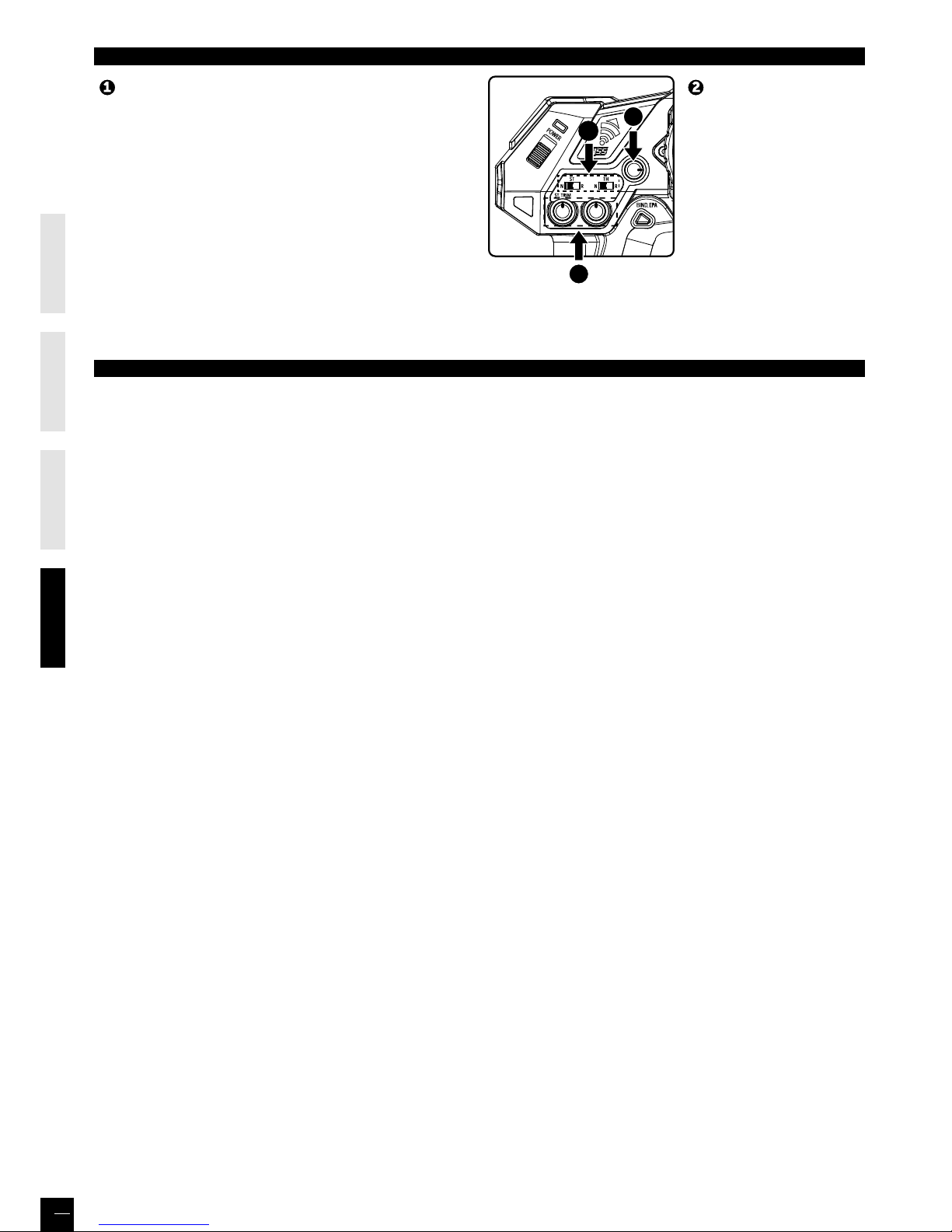
ENGLISHFRAN
Ç
AISDEUTSCHESPAÑ OL
36
AJUSTES DE LA RADIO
Invertir boton esta utilizado para cambiar el sentido del servo de
direccion.
KT2S+ emisora viene con 2 tipos de inversion.
Servo de direccion y servo de gaz y freno
Inversion del servo de direccion: Inverte la direccion cuando el
volante de la emisora gira izquierda, la ruedas giran derecha.
Inversion del servo de gaz y freno: Inverte el gaz y freno cuando
tire el gatillo, el coche va atras. Cuando empuja el gatillo, el
modelo adelantera.
Utilizar el trim de
aceleracion “Throttle” para
ajustar si no obtiene la
posicion neutral
Utilizar el trim de direccion
“Steering” para ajustar el
punto neutro de la direccion
Invertir Trimming
PROGRAMACION ELECTRONICA DEL EPA (END POINT ADJUSTMENT)
La programacion del EPA esta hecha ya en la fabrica. Se puede areglar este areglaje de origen de la manera siguiente :
Si quieren realmente areglar el EPA, es muy importante leer las instrucciones siguientes.
1. Servo de direccion
a) Emisora y receptor encendidos (LED emisora verde fija), girar y mantener el volante de la emisora hasta el punto final en el
sentido que quieren areglar el EPA, y empuja 2 segundas sobre el boton «BIND/EPA» : la Led se vuelve roja fija.
b) Cuando la Led roja esta fija, se puede definir con precision el angulo maximal de direccion de las ruedas del lado elijido.
Cuando el angulo de volante esta elijido, empujar de nuevo mas de 2 segundas sobre el boton «BIND/EPA». La Led parpadea 2
veces verde y se queda fija.
Para confirmar este areglaje, parar y encender la emisora (OFF/ON).
c) Para vuelver a la valor maximal (hecha en la fabrica), seguir la operacion a), y en la operacion b), mantener el volante hasta su
punto maximo y quedar empujando 2 segundas sobre el boton «BIND/EPA». La Led parpadea 2 veces verde y se queda fija.
Para confirmar este areglaje, parar y encender la emisora (OFF/ON).
Para areglar el otro sentido (derecha o izquierda), seguir la operaciones a) y b) girado el volante en la otra posicion.
Esta muy importante hacer esas operaciones de un lado y despues el otro para tener las mismas valores al cambio de
direccion derecha o izquierda.
2. Servo gaz/freno (el EPA debe ser areglado para el gaz y freno solamente para los coches TERMICOS.
a) Emisora y receptor encendidos (LED emisora verde fija), accelerar al tope del gastillo de la emisora hasta el punto final, y
empuja 2 segundas sobre el boton «BIND/EPA» : la Led se vuelve roja fija.
b) Cuando la Led roja esta fija, se puede definir con precision la acceleracion maximal elijida.
Cuando la velocidad esta elijida, empujar de nuevo mas de 2 segundas sobre el boton «BIND/EPA». La Led parpadea 2 veces
verde y se queda fija.
Para confirmar este areglaje, parar y encender la emisora (OFF/ON).
c) Para vuelver a la valor inicial (hecha en la fabrica), seguir la operacion a), y en la operacion b), mantener el gastillo hasta su
punto maximo y quedar empujando 2 segundas sobre el boton «BIND/EPA». La Led parpadea 2 veces verde y se queda fija.
Para confirmar este areglaje, parar y encender la emisora (OFF/ON).
Para areglar el freno, seguir la operaciones a) y b) empujar el gastillo al punto final.
Esta muy importante hacer esas operaciones una despues la otra.
3
2
4
Page 37
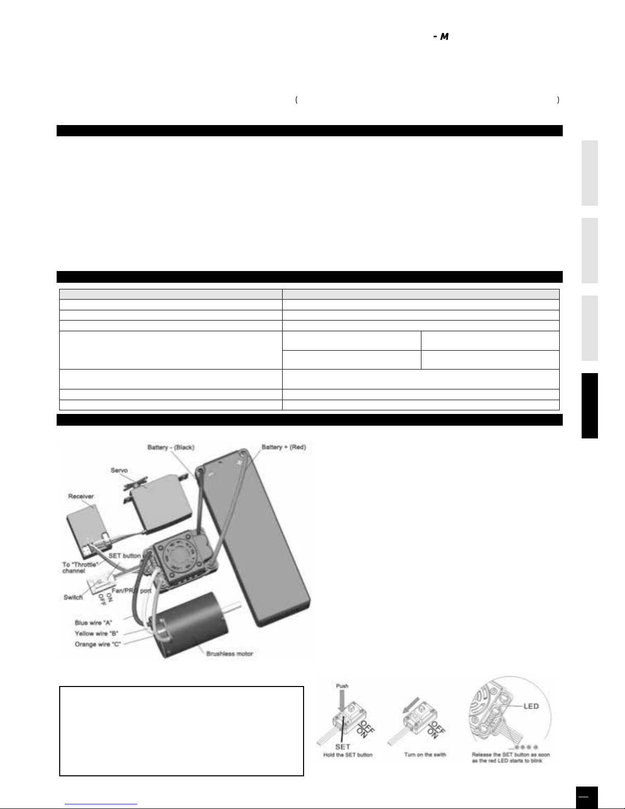
ENGLISHFRAN
Ç
AISDEUTSCHESPAÑ OL
37
Sistema de alta potencia para RC, puede ser muy peligroso, por favor, lea atentamente este manual. Hobbytech no tiene control
sobre el uso correcto de esta instalación, aplicación o mantenimiento de productos, no se asume responsabilidad ni daños,
pérdidas o gastos derivados de la utilización del producto. Cualquier reclamación que surja de la operación negligente, mal
funcionamiento, etc… puede ser denegada
ADVERTENCIA! TODAS MODIFICACIONES DEL PRODUCTO EJEMPLO: SOLDADURA, CAMBIO DE CONECTORES O DE CABLES
SE RESULTARA UNA ANULACIÓN INMEDIATA DE LA TOMA DE GARANTÍA DE NUESTRO SERVICIO DESPUÉS DE VENTA.
CARACTERISTICAS
1. Compatible con todos los motores sin sensor y la mayoría de los motores sin escobillas sensored
2. Excelente puesta en marcha, la aceleración y las características de linealidad
3. 2 modos de funcionamiento (modo de avance, avance / marcha atrás
4. Proporcional función de frenado ABS con 5 medidas de ajuste de la máxima fuerza de frenado, 8 pasos de ajuste de freno de
motor y 4 pasos de ajuste de fuerza inicial de frenado
5. 4 modos de arranque (También llamado «Punch») de «muy suave (Nivel 1)» a «muy agresivo (nivel 4)»
6. Múltiples funciones de protección: de corte de baja tensión / protección contra el calor / pérdida de señal de acelerador /
protección del motor bloqueado
7. Programable por el usuario. Fácil de programar con el botón «SET» en el variador y también es compatible con la tarjeta LED (opcional)
8. A prueba de salpicaduras y al polvo
ESPECIFICACIÓNES
Model KONECT 50AMP WP “by HOBBYWING”
Cont./ Burst Current 50A / 300A
Resistencia 0.0010ohm
Coches adecuados 1/10 Pista y Todo terreno
Motores adecuados
2S LiPo 6 cells NiMH
On-road ≥ 11T
O-road ≤ 14T
Motor 3650
On-road ≥ 8T
O-road ≤ 11T
Motor 3650
3S LiPo 9 cells NiMH
Baterías
4-9 elementos NiMH
2-3 elementos Li-Po
BEC Salida 6V / 2A
Dimensiones & Peso 48,5x38x32 & 90g
ANTES DE UTILIZAR SU NUEVO VARIADOR
ADVERTENCIA! ESTE SISTEMA ES MUY POTENTE, PARA
SU SEGURIDAD, CUANDO ENCIENDA EL VARIADOR
MANTENGA LAS RUEDAS ALEJADAS
1. Conectar el variador, el motor, el receptor y la bateria
como el dibujo
Cuando se utiliza motor sin escobillas y sin sensores Hall,
los cables A, B, C del Variador se puede conectar con los
cables del motor libremente (sin ningún tipo de secuencia).
Si el motor funciona en sentido contrario, por favor, cambie
las dos conexiones de cable
2.
Rango de ajuste de gas (calibración del rango del acelerador)
Con el fin de hacer que el Variador se ajuste al rango del
acelerador de la emisora, debe calibrar el mismo cuando se
empieza a utilizar un nuevo Variador, o un nuevo transmisor,
o para cambiar la configuración de la posición neutral de la
maneta del gas, los parámetros de la EPA o ATV… El Variador
no puede funcionar correctamente. Hay 3 puntos necesario
establecer: “gas a fondo”, “marcha atrás” y el “punto neutro”.
Las siguientes imágenes muestran como establecer el rango
del acelerador.
A) Apague el ESC, encender el transmisor, fijar la
dirección del canal de aceleración a «REV», conjunto
la «EPA / ATV» valor del canal de aceleración «100%»,
y deshabilite la función del ABS de su transmisor.
B) Manteniendo pulsada la tecla «SET» y encienda el
interruptor del ESC, y posteriormente suelte la tecla
“SET”; el LED rojo comienza a parpadear. (Note 4)
CONTROLADOR ELECTRÓNICO DE VELOCIDAD 50AMP BRUSHLESS WATERPROOF ANUAL DE UTILIZACIÓN
Page 38
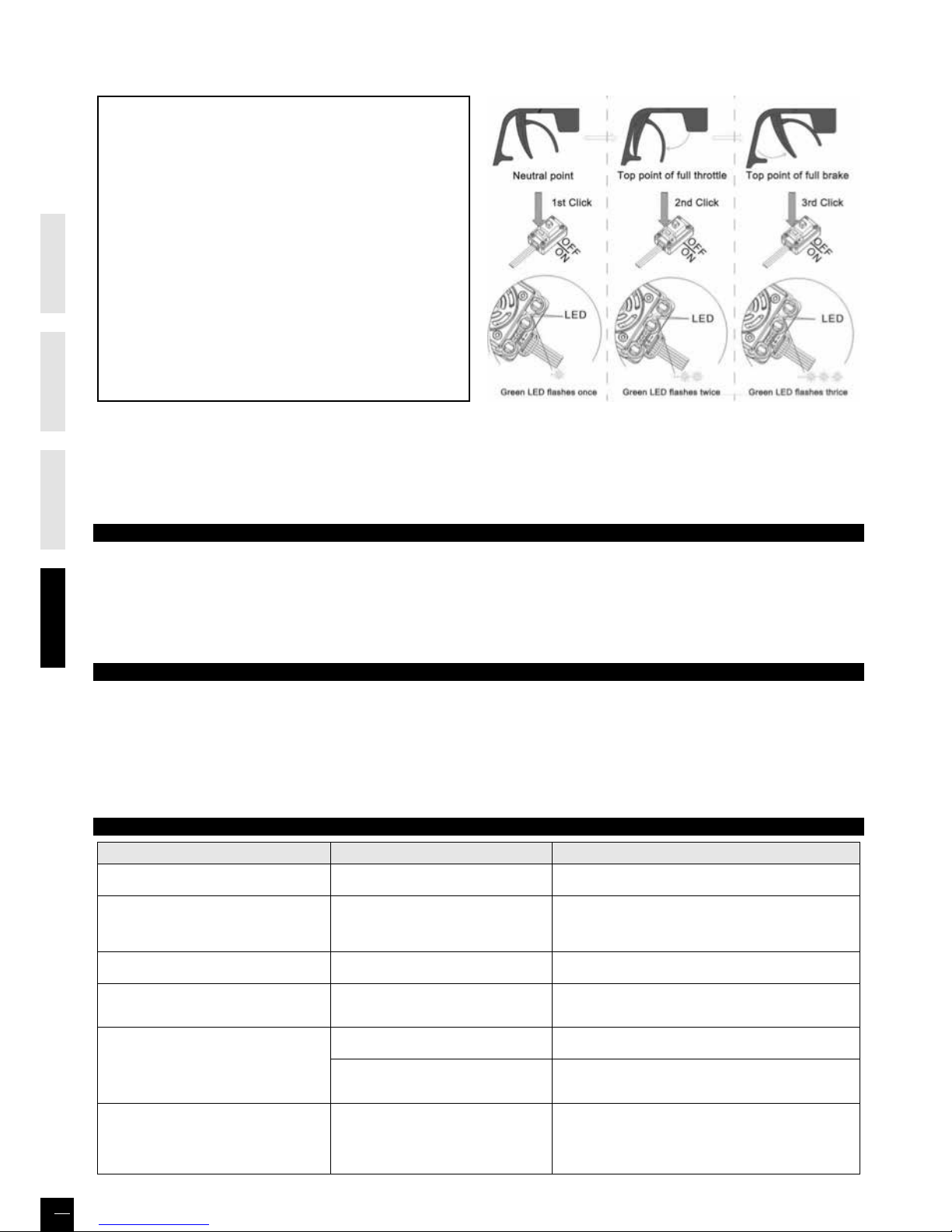
ENGLISHFRAN
Ç
AISDEUTSCHESPAÑ OL
38
Note 4: Si no liberan la tecla «SET» tan pronto como el LED rojo comienza a parpadear, el variador entrará en el modo de programa,
en este caso, por favor apague el variador y vuelve a empezar desde el paso A al D.
C) Establecer los 3 puntos en función de los pasos
mostrados en las imágenes en el lado derecho.
1) El punto neutro
Mover el gatillo hasta el punto neutro, y luego haga clic en
la tecla SET, el LED verde parpadea una vez.
2) El punto de aceleración máxima
Mueva el stick del gas hasta las posición de gas a fondo,
a continuación, haga clic en la tecla SET, el LED verde
parpadea dos veces.
3) El punto de la marcha atrás
Mover la palanca de gas hasta la posición de atrás maxima,
a continuación, haga clic en la tecla SET, el LED verde
parpadea 3 veces.
D) Rango del acelerador está calibrado; motor se puede
iniciar después de 3 segundos.
3. Compruebe el LED de estado en funcionamiento normal
1) Por lo general, si el acelerador está en el rango neutral, ni el LED rojo ni el LED verde estarán encendidos.
2) Se enciende el LED rojo cuando el coche está en marcha hacia adelante o hacia atrás y parpadeará rápidamente cuando el
coche está frenando
3) Se enciende el LED verde cuando el acelerador se mueve hasta el punto superior (punto final) marcha adelante o ma
rcha atrás.
TONAS DE ALERTA
1) Entrada de voltaje anormal:
El Variador comprueba la tensión de entrada cuando esta encendido, si el voltaje está fuera del rango normal, se escuchara un
tono de alerta: «bip-bip, bip-bip, bip-bip-» (el intervalo entre cada grupo de “bip-bip” es de un segundo”.
2) Señal del acelerador anormal:
Cuando el ESC no puede detectar la señal normal del acelerador, se escuchara el siguiente tono: «bip, bip, bip» (A intervalos de
2 segundos entre cada “bip”).
FUNCIÓN Y PROTECCIÓN
1) Protección de corte baja tensión : si el voltaje de la batería LiPo está más bajo que el asignado de fábrica durante más de 2 segundos,
el variador se para. Anotar que el variador no funcionara de nuevo si un elemento del pack de batería LiPo es inferior a 3,5V.
Para las baterías NiMh, si el voltaje de la batería esta entre de 9 a 12V, estará considerado por una batería de LiPo 3S. Si el voltaje
esta inferior a 9V estará considerado como una batería LiPo 2S.
2) Protección térmica : Cuando la temperatura del variador esta supere durante 5s al valor de temperatura máxima de fábrica, el
arriado se parara. Sera imposible de arreglar lo.
3) Protección perdida de señal : el variador se parara si la señal se pierde durante mas que 0,2s.
SOLUCIÓN DE PROBLEMAS
PROBLEMA POSIBLE RAZÓN SOLUCIÓN
Tras el encendido, el motor no funciona, y el
ventilador no funciona
Las conexiones entre la batería y el ESC no
son correctas.
Compruebe las conexiones eléctricas reemplazar los
conectores.
Tras el encendido, el motor no puede
funcionar, pero emite «bip-bip, bip-bip» tono
de alerta. (Cada grupo de «beep-beep-» tiene
un intervalo de tiempo de 1 segundo)
Tensión de entrada es anormal, demasiado
alta o demasiado baja
Compruebe la tensión de la batería
Tras el encendido, el LED rojo esta encendido,
el motor no funciona
Señal del acelerador es anormal
Conecte el cable de control en el canal del acelerador del
receptor correctamente
El motor funciona en la dirección opuesta
cuando se acelera
1) Las conexiones de los cables entre el
Variador y el motor no es correcta
2) El chasis es diferente del diseño estándar
Intercambie dos hilos las conexiones entre el Variador y el
motor
El motor de repente deja de funcionar, mientras
que estaba trabajando
La señal del acelerador se pierde
Compruebe el transmisor y el receptor
Compruebe el cable de señal del canal de aceleración de su receptor
.
El Variador ha entrado en el modo
de tensión baja o protección sobrecalentamiento
LED rojo parpadea significa la protección de baja tensión.
El LED verde parpadea significa exceso de protección contra el calor
Cuando se acelera rápidamente, el motor se
detiene o se estremece
1) La batería tiene una baja por mala
Rendimiento
2) La relación piñón/corona es muy pequeña
3) El «modo de inicio (Punch)» de la ESC es
demasiado agresivo
1) Utilice una batería mejor
2) Utilice menor KV motor o cambiar el tipo de equipo, elegir
un piñon más pequeño
3)
Seleccione una opción más suave para el modo de inicio «(Punch)»
PROGRAMACIÓN DEL VARIADOR
1. Métodos de Programación
Note5 : • En el proceso del programa, cuando el LED parpadea, el motor emite un tono «Beep» al mismo tiempo
• Si el número «N» es más grande que el «5», se utiliza un flash de tiempo y tono «bip» largo para representar a «5»,
por lo que es fácil de identificar los elementos con número de serie más grande.
Por ejemplo, si el LED parpadea:
« Un flash largo + 1 flash de poco tiempo» (Sonidos de motor»Beep-Beep») = N º 6 del artículo
« Un flash largo+ 2 destellos poco tiempo» (Sonidos de motor»Beep-BeepBeep») = N º 7 del artículo
« Un flash largo+ 3 destellos poco tiempo» (Sonidos de motor «Beep –BeepBeep Beep») = N º 8 del artículo, Y así sucesivamente...
Tabla de programacion
(Las palabras en cursiva indican valores por defecto)
1 2 3 4 5 6 7 8
1. Modo de ejecución
Adelante
con freno
Adelante / atrás
con freno
2. Freno de motor
0%
3. Corte por tensión
baja en celda
Non-Protection 2.6V/Cell 2.8V/Cell
3.2V
/Cell
3.4V
/Cell
4. Modo de salida Nivel1 Nivel2 Nivel4
5.
Fuerza máxima de f reno
25%
9
Programmable
Items
Basic Items
Programmable Value
3.0V
/Cell
10% 20% 40% 60% 80% 100%
100%
5%
75%
Nivel3
50%
Page 39

ENGLISHFRAN
Ç
AISDEUTSCHESPAÑ OL
39
PROGRAMACIÓN DEL VARIADOR
1. Métodos de Programación
Note5 : • En el proceso del programa, cuando el LED parpadea, el motor emite un tono «Beep» al mismo tiempo
• Si el número «N» es más grande que el «5», se utiliza un flash de tiempo y tono «bip» largo para representar a «5»,
por lo que es fácil de identificar los elementos con número de serie más grande.
Por ejemplo, si el LED parpadea:
« Un flash largo + 1 flash de poco tiempo» (Sonidos de motor»Beep-Beep») = N º 6 del artículo
« Un flash largo+ 2 destellos poco tiempo» (Sonidos de motor»Beep-BeepBeep») = N º 7 del artículo
« Un flash largo+ 3 destellos poco tiempo» (Sonidos de motor «Beep –BeepBeep Beep») = N º 8 del artículo, Y así sucesivamente...
Tabla de programacion
(Las palabras en cursiva indican valores por defecto)
1 2 3 4 5 6 7 8
1. Modo de ejecución
Adelante
con freno
Adelante / atrás
con freno
2. Freno de motor
0%
3. Corte por tensión
baja en celda
Non-Protection 2.6V/Cell 2.8V/Cell
3.2V
/Cell
3.4V
/Cell
4. Modo de salida Nivel1 Nivel2 Nivel4
5.
Fuerza máxima de f reno
25%
9
Programmable
Items
Basic Items
Programmable Value
3.0V
/Cell
10% 20% 40% 60% 80% 100%
100%
5%
75%
Nivel3
50%
Page 40
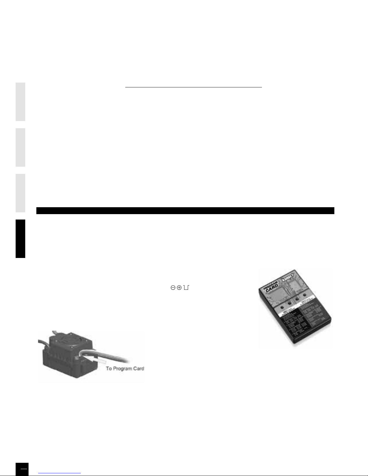
ENGLISHFRAN
Ç
AISDEUTSCHESPAÑ OL
40
2. Explicación de cada elemento programable
2.1. Modo de ejecución:
Con «Adelante con freno», el coche puede ir hacia adelante y frenar, pero no puede ir hacia atrás, este
modo es adecuado para la competición. «Adelante / atrás con freno» proporciona la función de marcha atrás, que es adecuada
para el entrenamiento diario. «Adelante / Atrás» utiliza el modo «solo clic» método para hacer que el coche vaya hacia atrás.
Al mover el stick de la zona de adelante hacia atrás a la zona,el coche va a ir hacia atrás inmediatamente. Este modo se utiliza
generalmente para el rastreador Rock.
2.2. Freno de motor (Drag Brake Force):
Establece la cantidad de freno de motor aplicado al dejar el stick en zona neutra
2.3 Corte por tensión baja en celda:
La función evita que la batería de litio se descargue de más. El Variador detecta voltaje de la
batería en cualquier momento, si el voltaje es inferior por un umbral de 2 segundos, la potencia de salida se reducirá un 70%, después de
10 segundos el motor se apagara, y el LED rojo parpadea cada segundo
“❏-❏-, ❏-❏-, ❏-❏-”.
Hay 6 opciones predeterminadas para este
artículo. Puede personalizar el umbral de corte mediante el uso de la tarjeta programadora de LCD (equipo opcional) para recortar con
un paso de 0,1 V, por lo que será más adecuado para todo tipo de baterías (NiMH, NiCd, Li-ion, Lipo, LFP , etc.) En este último caso, tenga
siempre presente que el valor no es personalizado para cada celda, que es para el paquete de batería completo.
2.4 Modo de salida (Start Mode «Punch»):
Seleccione «Nivel 1» a «Nivel 4», Nivel 1 tiene un efecto empezar muy suave, mientras que
Nivel 4 tiene un efecto comienzo muy agresivo. De Nivel 1 a Nivel 4, la fuerza de inicio es cada vez mayor.
2.5 Fuerza máxima de freno:
La
fuerza de frenado se relaciona con la posición de la palanca de gas. Fuerza máxima de frenado se refiere a la fuerza cuando el acelerador se
encuentra en el extremo superior de la zona de atrás. Una fuerza de frenado de grande puede acortar el tiempo de frenado, pero también
puede dañar el equipo.
3. Reponer todos los elementos a los valores predeterminados de fabrica
En cualquier momento cuando el acelerador se encuentra en zona neutral (excepto en el proceso de calibración del acelerador
o en el modo de programación del ESC), mantenga la tecla «SET» durante más de 3 segundos, el LED rojo y el LED verde se
encenderán al mismo tiempo, lo que significa cada elemento programable se restablece el valor predeterminado.
ACCESSORIOS Y OPCIONES
1. Ventilador (12V)
El ventilador “alta voltaje” es necesario cuando utilizan una batería 3S LiPo o Ni-MH de más de 6 elementos.
ADVERTENCIA! Anotar el ventilador de origen (5v) está recomendado solamente en asociación con una batería 2S LiPo o Ni-MH
de 4-6 elementos.
NO UTILIZAR con una batería 3S LiPo o Ni-MH de más de 6 elementos. Averiguar la etiqueta del ventilador antes de usar.
2. Tarjeta de LED de programación
Programar el ESC con la tarjeta de LED de programación (equipo opcional).
Solamente tienen que enchufar los cables del variador (3 cables: negro, rojo y blanco)
en la tarjeta (la toma se situe sobre el lado y marcado por
...) conectar la batería
principal al variador. Después de segundos, los valores de programa se despacharan
sobre la tarjeta. Utilizar los botones “ITEM” y “VALUE” para seleccionar los elementos de
programo y sus nuevos valores, después empujar “OK” para confirmar los nuevos reglajes
del variador.
• La toma de la tarjeta de programación es la misma que la del ventilador. Desconectar el cable del ventilador, y conectar al
mismo sitio que el de la tarjeta de programación para unir la al variador.
Item # KN-PROGRAM-CARD
Page 41

RÉF. / ITEM
DÉSIGNATION / DESIGNATION
CA-123
Carrosserie Buggy BXR.S1 prepeinte
BXR.S1 buggy prepint body
HT-427
Pneus buggy 1/10 avant complet mini picots
Front Off road 1/10 tyres set mini pin
HT-428
Pneus buggy 1/10 arriere complet mini picots
Rear Off road 1/10 tyres set mini pin
HT-501551
Aileron buggy 1/10 plastique noir
1/10 off road black plastic wing
HT-570601
Amortisseurs avants BXR.S1
Front BXR.S1 Shocks L=75mm
HT-570602
Amortisseurs arrières BXR.S1
Rear BXR.S1 Shocks L=95mm
KN-0420
Servo Konect 04kg-20s pignons plastiques
Konect 4kg -20s plastic gear servo
KN-10BL50-
WP
Controleur Brushless 1/10 50A Waterproof
1/10 Waterproof Brushless 50A Controler
KN-183212
Pignon moteur acier 12Dts 32DP
32DP 12T metal motor gear
KN-3652SL-
4600
Moteur Brushless 1/10 taille 3652 4600kv
3652SL - 4600KV Brushless motor
KN-KT2S+/
SET
Ensemble radio 2.4 GHZ Konect KT2S +
2.4 GHZ Radio Konect KT2S +
KNLP2S2200
Batterie LiPo 2S 2200Kv
2S 2200Kv LiPo battery
REV-003
Etrier avant gauche et droite
L/R Front C-hub
REV-004
Axe etriers
C-Hub Pin
REV-008
Garniture slipper central
Center drive cup washer
REV-010
Guidage d’axe de triangle
Lower suspension hinge
REV-011
Axe amortisseur avant
Front shock shaft
REV-012
Axe amortisseur arrière
Rear shock shaft
REV-014
Entretoise Sup d’amortisseur
Shock cap bushing
REV-015
Axes de sauve servo
Steering servo saver post
REV-016
Canons de bras de sauve servo
Servo saver arm bushing
REV-024
Boule de chape
Ball stud
REV-025
Cardans arrieres BX10
Rear drive shaft BX10
REV-026
Vis etrier avant
C-Hub Screw
REV-027
Boule d amortisseur et de BAR
Shock and stabilizer ball
REV-028
Ecrous de roues
Wheel nut M4
REV-030
Pas inverse M3x26
Turnbuckle M3x26
REV-031
Pas inverse M3x35
Turnbuckle M3x35
REV-032
Pas inverse M3x44
Turnbuckle M3x44
REV-033
Boule sup barre anti-roulis
Stabilizer ball (upper)
REV-034
Ressort de sauve servo
Servo saver spring
REV-038
Barre anti roulis avant
Front sway bar
REV-039
Barre anti roulis arriere
Rear sway bar
REV-047
Etriers arrieres
Rear Hub set
REV-050
Support de tirant arriere
Rear tie-rod holder
REV-057
Set de cales de triangle arriere
Rear to-in plate/Lower Susp arm
RÉF. / ITEM
DÉSIGNATION / DESIGNATION
REV-160
Cardans CVD avants BX10 goupille 2mm
2mm pin BX10 CVD front shaft
REV-160DB
Axes de cardans CVD avants BX10 goupille 2mm
2mm pin BX10 CVD front shaft axle
REV-161
Bague entrainement cardans CVD Avant 2mm
2mm Pin Front CVD Drive Couple
REV-162
Noix de CVD avant 2mm
2mm Front CVD drive cup
REV-163
Securite CVD BX10 ST10
Security parts BX10 ST10 CVD
REV-167
Noix de cardan roue arriere 2mm
2mm Rear drive cup
REV-171
Maintien ressort chappes amortisseur BB
BB Shock bottom holder ball ends
REV-178
Couronne centrale 32 DP 56dts
32 Pitch Center Spur gear 56T
REV-184
Set complet slipper 32dp
32dp Center Slip Clutch Set
REV-BX001
Chassis principal aluminium BXR.S1
Main chassis Hobbytech BXR.S1
REV-BX002
Protections laterales Spirit BXR.S1/MT
Side Guard BXR.S1/MT
REV-BX003
Triangle avant/arriere BXR.S1
F/R lower suspension arm BXR.S1
REV-BX004
Set de cales de triangles avant BXR.S1/MT
BXR.S1/MT Front to-in plate/Lower Susp arm
REV-BX005
Pare choc avant BXR.S1
BXR.S1 Front bumper
REV-BX006
Platine avant plastique BXR.S1/MT
BXR.S1/MT Plastic Front Plate
REV-BX007
Renfort de chassis arrière BXR.S1/MT
BXR.S1/MT Rear Chassis Brace
REV-BX008
Support de diff et de moteur BXR.S1/MT
BXR.S1/MT Center diff and motor mount
REV-BX009
Entretoise montage cellule arrière BXR.S1/MT
BXR.S1/MT rear diff case plate
REV-BX010
Support de renfort arriere BXR.S1
BXR.S1 Rear Brace Holder
REV-BX011
Kit protection couronne et support recepteur BXR.S1/MT
BXR.S1/MT receiver plate + main gear plastic cover
REV-BX012
Cardan central avant BXR.S1/MT 74 mm
BXR.S1/MT center front drive shaft 74mm
REV-BX013
Cardan central arrière BXR.S1 97 mm
BXR.S1 center rear drive shaft 97mm
REV-BX014
Hexagone de roue avant alu clavette 2mm
2mm pin Front wheel alum adaptator
REV-BX015
Hexagone de roue arriere alu clavette 2mm
2mm pin Rear wheel alum adaptator
REV-BX016
Clavette entrainement hexagone 2x11.8mm
Front/Rear drive pin 2x11.8mm
REV-BX017
Ressort amortisseur avant BXR.S1 blanc 1,25x45mm
BXR.S1 front shock spring white 1,25x45mm
REV-BX018
Ressort amortisseur arrière BXR.S1 blanc 1,25x60mm
BXR.S1 Rear shock spring white 1,25x60mm
REV-BX019
Corps d amortisseur avant BXR.S1 diam 13 L=34mm
BXR.S1 Rear shock body diam 13 L=34mm
REV-BX020
Axe triangle avant BXR.S1/MT 3x44mm
BXR.S1/MT Front lower Susp pin 3x44mm
REV-SL029
Molette d’amortisseur pour SL
SL Shocks adjustable Screw
REV-SL030
Membranes d amortisseur Hobbytech SL
Hobbytech SL Shocks Bladders (4)
REV-SL047
Cellule differentiel pour SL
Pinion diff F/R Gearbox complety set for SL
REV-SL051
Bouchon amortisseur aluminium 13mm
13mm Aluminium shocks cap
REV-SL053
Corps d’amortisseur BXR.S1/MT/BX8SL diam 13 L=43mm
BXR.S1/MT/BX8SL Shock body diam 13 L=43mm
REV-SL055
Piston amortisseur 13mm
13 mm Shock piston
STICK-BXR.
S1
Planche de stickers Hobbytech BXR.S1 buggy
Hobbytech BXR.S1 buggy stickers sheet
RÉF. / ITEM
DÉSIGNATION / DESIGNATION
REV-059
Support de servo
Servo mount
REV-062
Support d aileron
Wing mounts
REV-063
Palonnier de servo
Servo horn arm
REV-064
Support de tirant avant
Front tie-rod holder
REV-066
Fusee avant droite/gauche
Front L/F steering block
REV-068
Entretoise d etrier avant
Front steering hub bushing
REV-069
Entretoise interne etrier arriere
Rear C-hub bushing
REV-070
Rondelle etrier
C-hub washer
REV-072
Kit de roulements
Bearing set
REV-077
Support carrosserie
F/R body post
REV-078
Barre de direction
Steering plate
REV-079
Kit plastique de direction
Steering set
REV-080
Corps de sauve servo
Servo saver pipe
REV-089
Ecrou de sauve servo
Servo saver nut
REV-095
Set chapes barre anti roulis
Sway bar ball end set
REV-103
Rondelle calage etrier arriere
Rear hub washer
REV-104
Rondelle calage triangle Ar
Rear arm washer
REV-114
Rondelle piston amortisseur
Shock piston washer 2.6x5x0.5
REV-117
Support amortisseur avant SURVOLT
Survolt Front Shock Tower
REV-119
Support amortisseur ar SURVOLT/ ST10
Rear shocks tower SURVOLT/ ST10
REV-140
Diff pignon noix de cardans av/ar
Pinion Diff Center F/R drive
REV-141
Diff pignon pignon d attaque 16Dts metal
Pinion Diff Metal Bevel Gear 16T
REV-142
Noix de cardans Diff Av/Ar
F/R diff drive cup set
REV-143
Couronne de differentiel
Differential bevel gear
REV-144
Joint torique de differentiel
Differential O-Ring
REV-145
Joints de differentiels
Differential Gaskets
REV-146
Pignons planetaires de differentiel
Diff Bevel gear 13T
REV-147
Bague de boitier de differentiel
Diff case bushing
REV-148
Pignons satellites de differentiel
10T Diff Bevel gear
REV-149
Axes des satellites du differentiel
Diff. Bevel Gear Shaft
REV-150
Corps de differentiel
Diff case
REV-151
Kit de visserie complet BX10/ST10
BX10/ST10 Complety screw set
REV-153
Differentiel a pignon complet
Pinion Diff complety set
REV-154
Bagues superieures de xation d’amortisseur
Shock cap bushing
REV-157
Nouvelles chapes avant/arriere/direction
New F/R/steering Ball Cups
REV-158
Boite etanche 1/10eme
Watreproff receiver box
41
Page 42

REV-145
REV-148
REV-149
REV-146
REV-072
REV-142
REV-143
REV-144
REV-146
REV-150
REV-144
REV-142
REV-072
REV-147
REV-BX007
CA-123
REV-158
REV-030
REV-066
REV-070
REV-003
REV-070
REV-026
REV-068
REV-BX006
REV-157
REV-038
REV-032
KN-183212
REV-157
REV-117
REV-014
REV-BX004
REV-SL047
REV-BX003
REV-BX020
KN-KT2S+/SET
REV-160DB
REV-BX005
KN-10BL50-WP
KN-3652SL-4600
KN-0420
KN-LP2S2200
HT-570601
REV-114
REV-011
REV-154
REV-012
REV-027
REV-072
REV-024
REV-BX014
REV-BX008
REV-BX012
REV-BX013
REV-BX002
REV-BX010
REV-BX011
REV-BX011
REV-BX003
REV-080
REV-077
REV-016
REV-078
REV-079
REV-184
REV-161
REV-153
REV-089
REV-034
REV-015
REV-162
REV-171
REV-031
REV-157
REV-063
REV-064
REV-059
REV-160DB
REV-162
REV-163
REV-161
REV-160
REV-SL029
REV-BX019
REV-SL055
REV-SL051
REV-SL030
REV-BX017
REV-BX018
REV-SL053
42
Page 43

REV-119
REV-014
REV-039
REV-033
HT-501551
STICK-BXR.S1
KN-LP2S2200
REV-072
REV-184
REV-178
REV-072
REV-008
HT-570602
REV-025
REV-072
REV-151
REV-103
REV-104
REV-072
REV-024
REV-047
REV-069
REV-167
REV-BX001
REV-BX015
REV-BX014
REV-BX008
REV-BX013
REV-BX016
REV-BX002
REV-010
REV-057
REV-032
REV-157
REV-095
REV-153
REV-050
REV-024
REV-050
REV-077
REV-BX010
REV-BX011
REV-BX003
REV-SL047
REV-SL047
REV-BX009
REV-BX003
REV-062
REV-004
REV-140
REV-141
REV-072
REV-184
HT-427
HT-428
REV-028
43
Page 44

KN-183213/4/5/6/7
Pignon 32 DP
HW30501003
Carte de programmation
Program card
KN-1714
Servo Konect 17kg-14s pignons métal
Konect 17kg-14s metal gear servo
KN-COMBO-B4
COMBO BRUSHLESS 50Amp WP + moteur 4P 3652SL
5400Kv +carte de prog
COMBO BRUSHLESS 50Amp WP + 4P 3652SL 5400Kv
motor + program card
OPTION PARTS
HT-429
Pneus buggy 1/10 Square avant complet
Front Off road 1/10 tyres set Square
HT-430
Pneus buggy 1/10 Square arrière complet
Rear Off road 1/10 tyres set Square
HT-431
Pneus buggy 1/10 All Terrain avant complet
Front Off road 1/10 tyres set AllTerrain
HT-432
Pneus buggy 1/10 All Terrain arrière complet
Rear Off road 1/10 tyres set AllTerrain
KN-ELECTRO-DOC
Testeur de batteries + testeur servo
Battery Voltage Capacity Checker + servo tester
KN-LIPO.BAG
Housse de charge KONECT pour accus Lipo
Universal LiPo Battery safety bag KONECT
KN-LIPO220
Chargeur LiPo 220V
220V LIPO Charger
KN-LP.RT-2S5000.SY
Konect Lipo 5000mah 7.4V 100C 2S2P SHORTY
Konect Lipo 5000mah 7.4V 100C 2S2P SHORTY
HT-510001N/R
Palonnier alu direction Noir ou Rouge 25T
Steering alum servo horn BLACK or RED 25T
HT-510007G
Palonnier en alu bras simple ORANGE
Steering aluminium servo horn with universal adaptor
HT-504007
Sac de transport 1/10ème Noir
1/10 Car Bag Black
HT-504005
1/8 or 1/10 Pit Mat (620x420mm) with magnet holder
Tapis de stand 1/10ème ou 1/8ème (620x420mm) avec
support magnétique
REV-OP04
Fusees avants en aluminium
Aluminium front steering
KN-PRODUO
Chargeur ProDuo 2x80W AC/DC
2x80W AC/DC ProDuo Charger
KN-ULTRAPEAK4
Chargeur Ultrapeak 4
ULTRA PEAK 4 charger
REV-176
Fusees avants en aluminium
Aluminium front steering
KN-LP2S4200
Konect Lipo 4200mah 7.4V 40C 2S1P 31Wh (Stick Pack
Dean)
Konect Lipo 4200mah 7.7V 40C 2S1P 31Wh (Stick Pack
Dean )
KN-LP2S5200
Konect Lipo 5200mah 7.4V 50C 2S1P 38.4Wh (Slim Pack
Dean )
Konect Lipo 5200mah 7.7V 50C 2S1P 38.4Wh (Big Pack
Dean )
KN-MULTI80RS
Chargeur AC / DC 80W Multi-Fonctions type RS
AC / DC 80W AC/DC Multi-Fonctions RS type
KN-MULTI60-PLUS
Chargeur AC / DC 60W Multi-Fonctions charge / decharge
equilibreur
MULTI60-PLUS AC/DC 60W multifunction Charger
44
Page 45

REV-OP11
Supports de tirants arrieres en aluminium(D G)
Aluminium Rear Turnbuckle Holder(L R)
REV-OP12-NEW
Cardans arrières Option CVD Revolt/Survolt BX10
BX10 Survolt/Revolt Rear CVD
REV-OP14
Supports de tirants avants en aluminium(D G)
Aluminium Front Turnbuckle Holder(L R)
REV-OP15
Support amortisseur avant carbone BX10
BX10 Carbon Fiber front shocks tower
REV-OP18
Barre de direction en aluminium
Aluminium Steering Plate
REV-OP19
Kit de conversion complet diff pignon
Gear Diff Conversion set
REV-OP16
Support amortisseur arriere carbone BX10/ST10
BX10/ST10 Carbon Fiber rear shocks tower
REV-OP17
Set sauve servo en aluminium
Aluminium Servo saver set
REV-OP05
Etriers avants en aluminium
Aluminium front C-Hub
REV-OP06
Etriers arrieres en aluminium
Aluminium rear C-Hub
REV-OP09
Cale de pincement 2.5 en aluminium
Aluminium Rear Toe in Plate2.5¦
REV-OP10
Cale de triangles inf arrieres en aluminium
Rear Lower Sus. on Arm Holder
REV-OP25
Noix de diff avant ou arrière en acier traité dur
Extra strong F/R Diff Drive Joint
REV-OP29
Support diff central BXR.S1/MT en aluminium
BXR.S1/MT Aluminium Slipper mount
REV-OP26
Cale avant aluminium cellule avant BXR.S1/MT
Front aluminium plate front diff case
REV-OP28
Support moteur en aluminium en 2 parties pour BXR.S1/MT
2 parts aluminium motor mount
REV-OP27
Cale arrière aluminium cellule avant BXR.S1/MT
Rear aluminium plate front diff case
45
Page 46

NOTES
46
Page 47

47
Page 48

Specification are subject to change without notice.
Photograph shows model after assembly and painting.
Les spécificités peuvent changer sans information préalable.
Les photos sont non contractuelles.
El fabricante puede modificar los kits sin previsio aviso.
Las fotos no son contractuales.
Spezifikation können ohne vorherige Ankündigung ändern.
Eektive Abbildung zeigt das Modell in Montage und Lackierung.
info@hobbytech-rc.com General information
 Loading...