

Page 1
INSTRUCTION
MANUAL
• This is not a toy! Not suitable for children under 14 years old without adult supervision.
• Ceci n’est pas un jouet. Ne convient pas aux enfants de moins de 14 ans sans la surveillance d’un adulte.
• Kein Spielzeug. Nichte geeignet für Kinder unter 14 Jahren ohne Aufsicht Erwachsener.
• No es un juguete. No recomendado para niños menores de 14 años.
ENGLISHFRAN
Ç
AISDEUTSCH
WARNING !
This vehicule deliveres a very powerfull velocity.
If the handling and the instructions is not followed with all attention needed, a lot of parts can be damaged easily.
It is better to start slowly to learn how to control this amazing power !
ATTENTION !
Ce véhicule possède une puissance extrêmement importante.
Le pilotage et les instructions doivent être eectués avec la plus grande attention.
De nombreuses pièces peuvent se détériorer ou casser très rapidement si vous n’apprenez pas d’abord à piloter et à contrôler la puissance
de ce véhicule !
ACHTUNG!
Dieses Fahrzeug ist extrem wichtig.
Die Lenkung und Anweisungen müssen mit größter Aufmerksamkeit durchgeführt werden.
Viele Teile beschädigt werden oder brechen können sehr schnell, wenn Sie nicht zuerst
lernen zu fahren und die Kraft dieses Fahrzeug zu steuern!
CUIDADO!
Este Vehiculo tiene una potensia muy importante.
El pilotaje y las instucciones tienen que ser dirigidas con la maxima atencion.
El utilisador tiene que aprender a conducir y a controlar la potenensia del
vehiculo sino muchas piezas puden estropearse o romperse immediatamente
Page 2
2
Curved lexan scissors
Ciseaux a lexan courbes
EX 421200
HT 421900
Hex wrench complety set
(1,5-2-2,5-3mm)
Coret de tournevis allen
EX 421939
Wheel nuts wrench 17mm
Clé à roue 17mm
EX 421984
Aluminium Multi-tool for Shocks
Outil multifonction pour amortisseur
Multifonction pliers complety set
Gamme multifonction de pinces
Turnbuckle wrench
Clé de réglage biellette
EX-421942
EX-421943
EX-421945
4.0MM
5.0MM
6.0MM
Li-Po safety bag
Housse de charge LiPo
KN-LIPOBAG
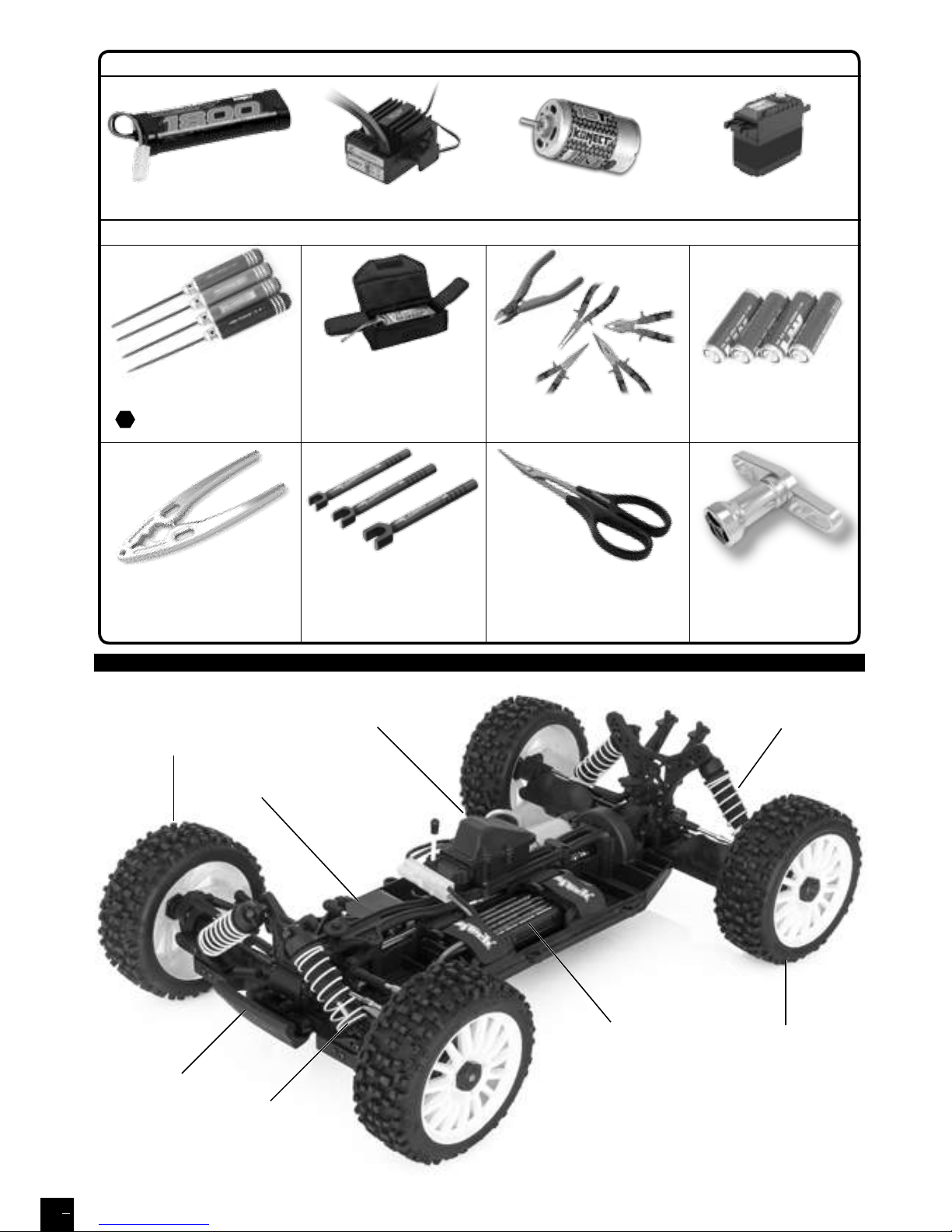
TOOLS REQUIRED NOT INCLUDED IN THE KIT / OUTILLAGE REQUIS NON INCLUS DANS LE KIT
4xAA Alkaline batteries
4 piles Alkaline R6
PROVIDED WITH THE CAR / FOURNIS AVEC LE VÉHICULE
KONECT 550 16T Motor KONECT 4Kg .20s ServoKONECT 40Amp brushed ESCKONECT 1800Amp 7.2V Ni-Mh Battery
CHASSIS
Front tyre
Batterie
Steering
servo
ESC
Rear tyre
Front
shock unit
Rear
shock unit
Front
Bumper
Page 3
ENGLISHFRAN
Ç
AISDEUTSCH
3
KONECT KT2S+ TRANSMITTER
FCC ID: YDTHBT1000 FCC Statement: This equipment has been tested and found to comply with the limits for Part 15 of the FCC rules. These limits are designed to provide reasonable
protection against harmful interference in a residential installation.
This equipment generates, uses and can radiate radio frequency energy and, if not installed and used in accordance with the instructions, may cause harmful interference to radio
communications.
However, there is no guarantee that interference will not occur in a particular installation. If this equipment does cause harmful interference to radio or television reception, which can be
determined by turning the equipment o and on, the user is encouraged to try to correct the interference by one or more of the following measures:
• Reorient or relocate the receiving antenna. • Increase the separation between the equipment and receiver.
• Connect the equipment to an outlet on a circuit dierent from that to which the receiver is connected.
This device complies with Part 15 of the FCC Rules. Operation is subject to the following two conditions:
(1) this device may not cause harmful interference,
(2) this device must accept any interference received, including interference that may cause undesired operation.
Notice: Modifications to this product will avoid the user’s authority to operate this equipment.
WARRANTY AND SERVICE INFORMATIONS
COMPONENT WARRANTY PERIOD
PLEASE READ THE FOLLOWING INFORMATION CAREFULLY !
Please note this is a high-quality hobby product and not a toy. Therefore, it is necessary that children under 14 years are
supervised by an adult. The guardians and / or parents have the responsibility to provide the appropriate guidance and
supervision of the minors .
This product has a 90 day warranty, which is only guaranteed to the original purchaser. The warranty valid only to products
that have been purchased from an authorized Hobbytech dealer. Warranty claims will be processed only with a valid proof of
purchase / receipts. If within the warranty period, a portion of the product fails due to manufacturing defects, then it is within
the discretion of Hobbytech to repair it or replace it. The decision to repair or replace the part will be taken by Hobbytech. After
use, we do not oer new for old warranty.
WARRANTY DISCLAIMER
This high performance model was made with highest attention and care and should be treated with respect. Excluded from
the warranty are components that have been damaged by wrong installation, mishandling, accident, operation, maintenance,
lack of maintenance and care, as well as abuse and / or repair attempts. Furthermore excluded from the guarantee are wearing
parts such as fuses and batteries, visual impairments, shipping -, transport costs.
WARRANTY CLAIM
Please contact your dealer with the warranty claim and / or repair. Your dealer and Hobbytech will make an proper decision
that will help you as soon as possible. For invalid warranty claims you may be charged for the processing costs before the parts
are returned. All repairs which are necessary by negligence or abuse are bill in advance. In case you decide that you not want
to repair your product then Hobbytech editing and reserves the right to charge shipping costs .
DECLARATION OF CONFORMITY IN ACCORDANCE WITH THE RADIO &
TELECOMMUNICATIONS TERMINAL EQUIPMENT (R&TTE) DIRECTIVE 1999/5EC.
Sarl Imodel
5 place de Rome
13006 Marseille
France
Declares that he following product : 1.SL.BX8.RUNNER-G / O
w/ KONECT KT2S+ Transmitter & Receiver
Item Number: KN-KT2S-PLUS/SET
Equipment class: 1
Complies with the essential requirements and other relevant provisions of the FTEG (Article
3 of the R&TTE directive)
• Protection of health and safety of the user and any other person, (article 3.1a of the
Directive)
Standards applied: EN 62311:2008
• The essential requirements of the Electromagnetic Compatibility Directive (article 3.1b)
Standards applied: EN 301 489-1 V1.9.2 (2011-09)
EN 301 489-3 V1.4.1 (2002-08)
• Eective use of the radio spectrum/orbital resource so as to avoid harmful interference
(article 3.2).
Standards applied: EN 300 440-1 V1.6.1 (2010-08)
EN 300 440-1 V1.4.1 (2010-08)
Manufacturer Address: Sarl Imodel
5 place de Rome
13006 Marseille
France
Date of issue: September 27, 2012
This product must not be disposed of with other
waste. Instead, it is the user’s responsibility to
dispose of their waste equipment by handing
it over to a designated collection point for the
recycling of waste electrical and electronic
equipment. The separate collection and
recycling of your waste equipment at the time of
disposal will help to conserve natural ressources
and ensure that it is recycled in a manner that
protects human health and the environment.
Help us to protect the environment and respect
our ressources !
i.A.
Page 4

ENGLISHFRAN
Ç
AISDEUTSCH
4
IMPORTANT - READ ThIS BEFORE RuNNINg
PlEASE READ All INSTRuCTIONS AND FAMIlIARIzE YOuRSElF WITh ThE PRODuCTS AND CONTROl BEFORE
OPERATION.
This product is not a toy. It is a high performance model product. It is important to familiarize yourself with the model, its
manual, and its construction before assembly and operation. Adult supervision is necessary
CAUTION
To avoid serious personal injury and property damage, operate all remotely controlled models in a responsive manner as outlined below.
R/C car models can exceed speeds of 40km/h (25mph), and cannot be stopped quickly.
❶ Never run R/C models on the street or highways, as it could cause or contribute to serious trac accidents.
❷ Never run an R/C model near people or animals, nor use people or animals as obstacles when operation R/C vehicles.
❸ To avoid injury to persons or animals, and damage to property, never run a R/C model in a confined or crowed area.
❹ Running R/C models into furniture or other inanimate objects will cause damage to the objects and the R/C models.
CAUTION DURING OPERATIONS
When the R/C model is in operation, dot not touch any of its moving parts, such as drive shafts, wheels, as the rotating parts
can cause serious injury.
❶ The vehicle motor gets very hot during running and could cause burns if touched.
❷ Make sure that no one else is using the same frequency as yours in your running area. Using the same frequency at the same
time, whether is driving, flying or sailing, can cause loss of control of the R/C models, resulting in serious accidents.
❸ Properly connect plugs. To prevent electrical shock and/or damage to the product resulting from a short-circuit; insulate
connections with heat shrink tubing or electrical tape. Before running vehicle, check that battery wiring and plugs are not so
loose as to drag on the ground. Properly secure cables using electrical tape or nylon tie-wraps.
❹ Sti rotation of gears, shafts, joints and wheels can burn out the motor. It’s recommended to check proper joint and shaft
rotation by using one 1,5V dry cell during assembly of the model.
A worn motor will overheat and result in a short running time. Replace a worn out motor as soon as possible.
❺ R/C models will run out of control when either the receiver or transmitter battery voltage drops o. Stop the vehicle
immediately when the car starts to show down to prevent it from running out of control.
SAFETY PRECAUTIONS
Follow the outlined rules for safe radio control operation.
Avoid running the car in crowed area and near small children.
Make sure that no one else is using the same frequency in your running area. Using the same frequency at the same time can
cause serious accidents, whether it’s driving, flying or sailing.
Avoid running in standing water and rain. If R/C unit, motor, or battery get wet, clean and dry throughly in a dry shaded area.
R/C operating procedures
❶ Make sure the transmitter controls and trims are in neutral. Switch on transmitter.
❷ Switch on receiver.
❸ Inspect operation using transmitter before running.
❹ Adjust steering servo and trim so that the model runs straight with transmitter in neutral.
❺ Reverse sequence to shut down after running.
❻ Make sure to disconnect/remove all batteries.
❼ Completely remove sand, mud, dirt etc
❽ Store the car and batteries separately when not in use
SETTING UP THE MODEL
To greatly enhance the overall performance of your car, it’s necessary to tune the vehicle to the track (and its surface
conditions) on which you will be racing. Make adjustments referring to the instruction manual, keeping in mind that “balance” is
the key word.
❶ Tires
Tires have a great influence on the performance of your car, and are normally the first components tuned. Select the right tires
for the track you are racing on.
❷ Toe-in and Toe-out
Adjusting the car toe-in a little, by pointing the wheel inwards, provides the car with good straight running and moderate
steering characteristics. Toe-out, which point the wheels outwards, gives sharp and crisp steering. Take care not to overdo.
❸ Camber angle
While taking the corners, the car is forced to go outwards, causing instability. The area of contact on each tire is determined
by the camber angle, and therefore the traction of the tires can be made greater or lesser by adjustment of camber angle. To
increase traction during cornering, adjust camber angle negative, and reduce traction, adjust for positive camber.
❹ Ground clearance and suspension drop
Ground clearance and/or rebound stroke has a great eect on stability during cornering, acceleration, and braking. Ground
clearance can be adjusted by altering damper spring tension and stiness.
❺ Gear ratio
Proper gear ratio should be determined by the available output power of the motor; type of battery; track condition and layout
It should be also noted that running the car on a good grip surface suggests use of pinion gear 1 teeth smaller, in order to
eectively use all of the available battery power.
Page 5
ENGLISHFRAN
Ç
AISDEUTSCH
5
F
unctions
Battery LED Indicator
Battery Installa
tion
Warning:
Never disassemble batteries or put the batteries in fire, chemical
agents, otherwise they may cause personal injuries or property
damages.
Battery Disposal:
Observe corresponding regulations about wasted battery
treatment regulations.
1. After running out of power, dispose of wasted batteries in d
esignated
areas far away from water supply, household areas and planted a
reas.
2. Submit the wasted batteries to specific recycling stations.
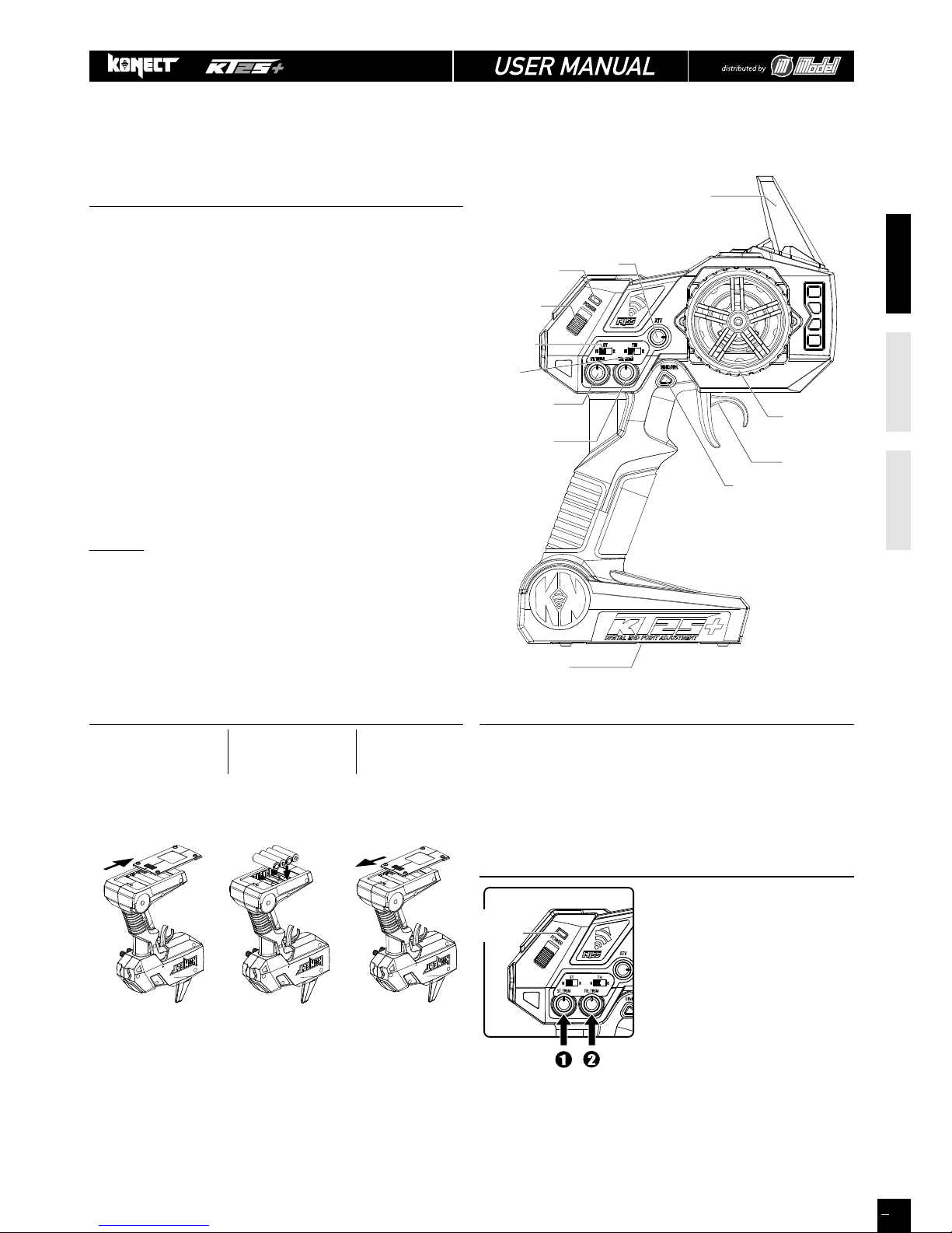
KT2S+ Transmitter
Steering Wheel : Control direction (Left / Right) of the RC
model.
Throttle Trigger : Control speed and direction (Forwar-
d/Brake/Backward) of the driving model.
Battery Compartment Tray : Cover and hold the batteries powering the
transmitter.
Antenna : Transmit signal to the model
Power ON / OFF : Power ON / OFF the transmitter
SYNC & Battery Indicator : Top Green LED light indicates synchroni-
zation status
and/or adequate battery power supply.
ATV : Adjustable Steering Rate by ATV dial
ST. Trim Dial : Adjust the neutral position of steering
servo when model wheels are straight
ahead.
TH. Trim Dial : Make sure the model stays still when
releasing the throttle trigger.
EPA : End Point Adjustment
WARNING
: accidental or intentional EPA function manipulation
may cause servos malfunction (reduced or inexistant travel).
Please reset maximum default values before contacting your
dealer (see «EPA», on page 8).
Works with 4 x 1.5V AA
Batteries (not provided),
KT2S+ can be operated a
few hours. Installation:
Remove the batte
ry
compartment cover as
shown belo
w.
Install the batteries
observing the polarity
marked on battery
compartment.
Then reicompartment cover as the
picture shown
below.
- During normal operation, the LED should be solid green ON-
- When battery voltage is dropped below 3.8V, the LED will become red
color and flashing very slowly, to indicate battery is low, you should replace
new battery as soon as possible
* Always turn on the transmitter first by sliding the switch on the left side
from bottom to top. The green lights above the switch should li
ght up. If not,
you need to check for low or incorrectly installed batteries.
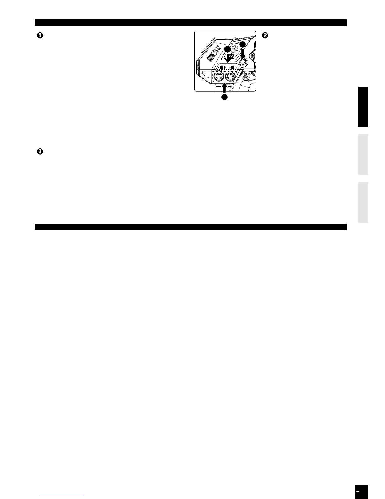
1. Steering : Adjust the steering trim to
keep the front wheels in straight line
when steering wheel remains in
NEUTRAL position.
2. Throttle : Adjust the throttle trim to
ensure the wheels stop rotating when
throttle trigger remains in NEUTRAL
position (only for nitro).
For EP vehicles, this button must be
set to NEUTRAL.
Pre-Run Check
LED
indicatorIndicator
LED
Battery
Compartment Tray
Steering Trim Dial
Steering Wheel
Throttle Trigger
Throttle Trim Dial
BIND / EPA Key
Antenna
Power Indicator
ATV
Power
ON / OFF
Throttle
Reverse Switch
Steering
Reverse Switch
TRANSMITTER
EVEN IF THIS CAR IS A READY TO RUN KIT, YOU STILL HAVE SOME LITTLE THINGS TO DO TO FAMILIARI ZE WITH YOUR
PRODUCT.
PLEASE FOLLOW THESE STEPS.
Page 6
ENGLISHFRAN
Ç
AISDEUTSCH
6
A
C
B
Pairing your receiver to your KT2S+
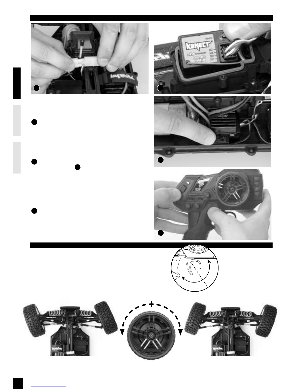
Place model on a block to prevent wheels from touching the
ground.
A
Connect battery to ESC. Fix the wire correctly with the
provided connectors.
You must check the signal of transmitter and receiver before
you operating it at first.
Make sure TH Trim is on neutral
TURN OFF THE TRANSMITTER AND RECEIVER
B
Press and Hold the BIND button on the receiver while
turning on the receiver
C
.
Release the BIND button when the LED flashes red.
While the red LED flashes, press the BIND button to select the
frame rate.
- Faster flashes= high frame rate (7ms), for digital servo
- Slower flashes= low frame rate (15ms), for analog servo
D Press and Hold the BIND/EPA key of the Transmitter (1),
and then turn on the transmitter (2), LED flahes green and the
Transmitter will communicate with the receiver. Release the
BIND/EPA button when the receiver LED is solid red, and the
transmitter is solid green, then your receiver is paired with your
transmitter.
BIND
D
(1)
(2)
HOW TO CONTROL YOUR MODEL
NEUTRAL POSITION
1. Pull up the trigger in order to brake or speed down
2. Pull the trigger in order to go forward or speed up
BRAKE / SPEED
DOWN POSITION
FORWARD / SPEED
UP POSITION
If the wheels operate in the opposite direction,
operate the servo reverse switch (ST in position NOR).
NEUTRAL
LEFT RIGHT
Page 7
ENGLISHFRAN
Ç
AISDEUTSCH
7
ABOUT THE RADIO SYSTEM
Reversing is used to change the response direction of steering
wheel and throttle trigger.
KT2S+ Transmitter features 2 reversing functions: Steering Reverse
and Throttle Reverse.
Steering Reverse: Reverse the response direction when operating
steering wheel.
Turning left steering wheel, the model turns right while turning
right the model turns left.
Throttle Reverse: Reverse the response direction when operating
throttle trigger.
Pushing forward throttle trigger the model moves backward while
pulling back, the model moves forward.
Adjustable Steering Rate enables to adjust the same maximum steering angle of servo on both sides (Left and Right) when
model makes steering. The Adjustable Steering Rate aects the sensitivity of servo. Reducing dual rate value can lower the
sensitivity of servo and reduce the same maximum steering angle on both sides. Remember to adjust the dual rate value within
the adjustment range: rotate clockwise = increase maximum steering angle; rotate counterclockwise = reduce maximum
steering angle.
The minimum adjustment of ATV (counterclockwise to the max) makes a zero steering angle.
KT2S+ features two trimming
functions:
Steering Trim and Throttle Trim.
Steering Trim Dial: Adjust the
neutral position of steering servo
when the wheels are straight
ahead.
Normally steering trim is adjusted
until the model can keep straight
tracks.
Throttle Trim Dial:
Adjust neutral position of throttle servo. Make sure the model
stays still when releasing the throttle trigger.
Reversing
Adjustable Steering Rate (ATV)
Trimming
PROGRAMMING THE END-POINTS
In order to avoid mechanical strain when steering to the maximum and/or accelerating and braking (nitro), an EPA function
(End Point Adjusment) can be digitally set. However ATV function can be used for steering end points, but on the left & right
together.
If you really want to use EPA function, please read the following instructions carefully:
1. Steering servo
a) Transmitter and receiver powered on (green LED on), turn the steering wheel to the maximum (on the side you want to set),
then hold down for 2 seconds the «BIND/EPA» button: LED turns solid red.
b) As long as LED is red, you can set the exact maximum turning angle of the wheels on the side you choose.
Once the angle is chosen, hold down again for 2 seconds the «BIND/EPA» button. LED flashes twice (light green/dark green)
then turns solid green.
IMPORTANT: Switch OFF and ON the transmitter to confirm the adjustment.
c) To reset the default value, follow a) step, then b) step, hold the steering wheel to the maximum and hold down for 2 seconds
the «BIND/EPA» button. LED flashes twice (light green/dark green) then turns solid green. IMPORTANT: Switch OFF and ON the
transmitter to confirm the adjustment.
To set the opposite side, follow a) and b) steps in the opposite side.
It is very important to perform these operations one by one.
2. Throttle servo (EPA is recommended only for nitro vehicles)
a) Transmitter and receiver powered on (green LED on), hold the throttle at forward-most position, then hold down for 2
seconds the «BIND/EPA» button: LED turns solid red.
b) As long as LED is red, you can set the exact your max throttle end-point.
Once the end-point is chosen, hold down again for 2 seconds the «BIND/EPA» button. LED flashes twice (light green/dark
green) then turns solid green.
IMPORTANT: Switch OFF and ON the transmitter to confirm the adjustment.
c) To reset the default value, follow a) step, then in b) step, hold the throttle at forward-most position, then hold down for 2
seconds the «BIND/EPA». LED flashes twice (light green/dark green) then turns solid green.
IMPORTANT: Switch OFF and ON the transmitter to confirm the adjustment.
To set the brake, follow a) step, then b) step braking to the maximum. You can now set your maximum brake end-point.
It is very important to perform these operations one by one.
3
2
4
Page 8
ENGLISHFRAN
Ç
AISDEUTSCH
8
ENGLISHF R AN
Ç
A I SD E UTSCH
High power system for RC model can be very dangerous, so we strongly suggest you read this manual carefully. In that
HOBBYTECH have no control over the correct use, installation, application, or maintenance of our products, no liability shall be
assumed nor accepted for any damages, losses or costs resulting from the use of the product.
ANY CLAIMS ARISING FROM THE OPERATING, FAILURE OF MALFUNCTIONING ETC. WILL BE DENIED. WE ASSUME NO LIABILITY FOR
PERSONAL INJURY, CONSEQUENTIAL DAMAGES RESULTING FROM OUR PRODUCT OR OUR WORKMANSHIP. AS FAR AS IS LEGALLY
PERMITTED, THE OBLIGATION TO COMPENSATION IS LIMITED TO THE INVOICE AMOUNT OF THE AFFECTED PRODUCT.
FEATURES
1. Water-proof and dust-proof for all weather races.
2. Small size with built-in capacitor module.
3. Automatic throttle range calibration, easy to use.
4.
protection.
5. Easily programmed with the jumpers.
SPECIFICATIONS
Model KN-BRUSH40
Cont. / Burst Current
Forward: 40A / 180A
Backward: 20A / 90A
Input 2-3S Lipo, 5-9 Cells NiMH/NiCd
Cars Applicable
1:10 Crawler, Tank & Boat
Motor
Limit
2 Lipo
or 5-6 NiMH
540 or 550 size motor ≥12T
RPM < 30000 @7.2V
3 Lipo
or 7-9 NiMH
540 or 550 size motor ≥18T
RPM < 20000 @7.2V
Resistance
FWD: 0.002 Ohm
BWD: 0.004 Ohm
Built-in BEC 2A/5V (Linear mode BEC)
PWM Frequency 1KHz
Dimension & Weight 46.5*34*28.5, 65g
BEGIN TO USE
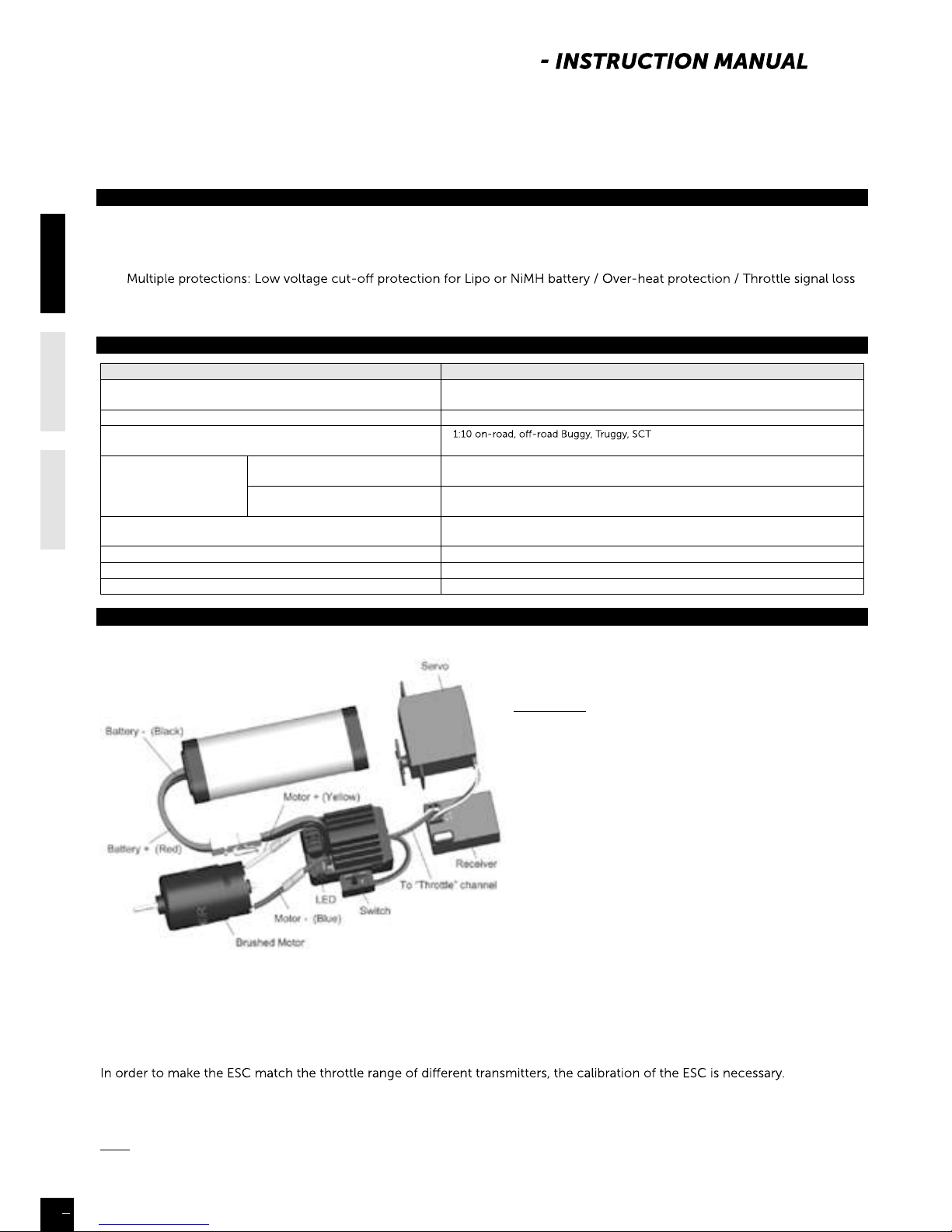
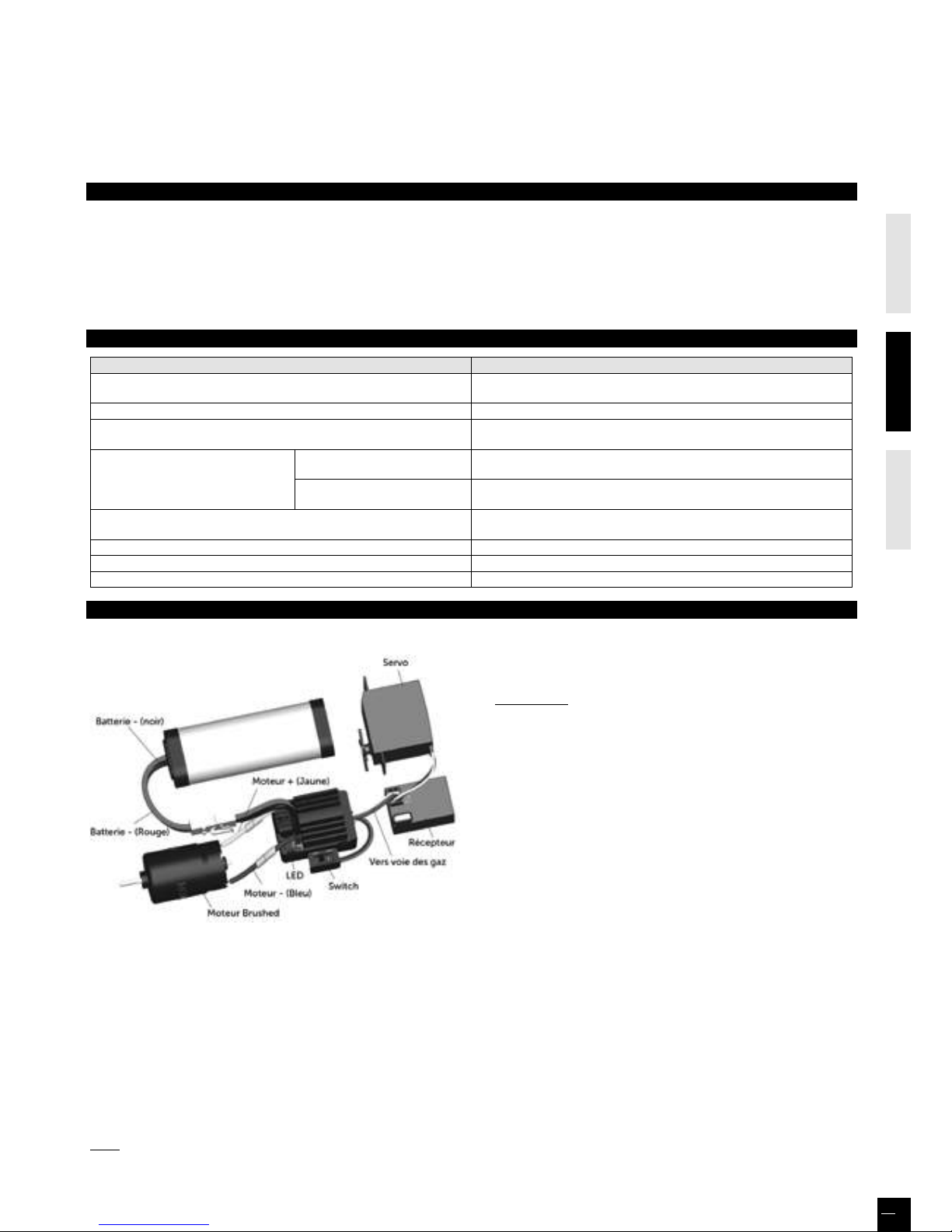
1. Connect the ESC, motor, receiver, battery and servo according to the following diagram
“+” and “-” wires of the ESC are connected to the battery
pack.
ATTENTION: The incorrect polarity will damage the ESC
immediately.
The control cable of the ESC (trio wires with black, red
and white color) is connected to the throttle channel of
the receiver (Usually CH2).
The “Motor +” and “Motor –” wires are connected to
ESC without any order. If the motor runs in the opposite
direction, please swap these two wire connections.
2. Set the Transmitter
Please set the “D/R”, “EPA” and “ATL” to 100% for throttle
channel (for transmitter without LCD, please turn the
knobs to the maximum value), and set the “TRIM” of the
throttle channel to 0 (for transmitter without LCD, please
turn the TRIM knob to its neutral position).
For FutabaTM and the similar transmitters, the direction of throttle channel shall be set to “REV”, while other radio systems shall
be set to “NOR”.
The “Fail Save” function of the radio system is strongly recommended to be activated. Please make sure that the motor can be
stopped when the “Fail Save” happens.
3. Throttle Range Setting (Throttle Range Calibration)
To calibrate the ESC, please turn on the transmitter, keep throttle stick at its neutral position, wait for 3 seconds to let the ESC
execute self-test and automatic throttle calibration. When the ESC is ready to run, a long beep sound is emitted from the
motor.
Note: Please calibrate the throttle range again when using a new transmitter or changing the settings of the neutral position of
throttle channel, D/R, ATV, ATL or EPA parameters, otherwise the ESC may not work properly.
40AMP BRUSHED WATERPROOF ESC
Page 9
ENGLISHFRAN
Ç
AISDEUTSCH
9
ENGLISHf r a N
ç
a I S
D E UTSCH
10
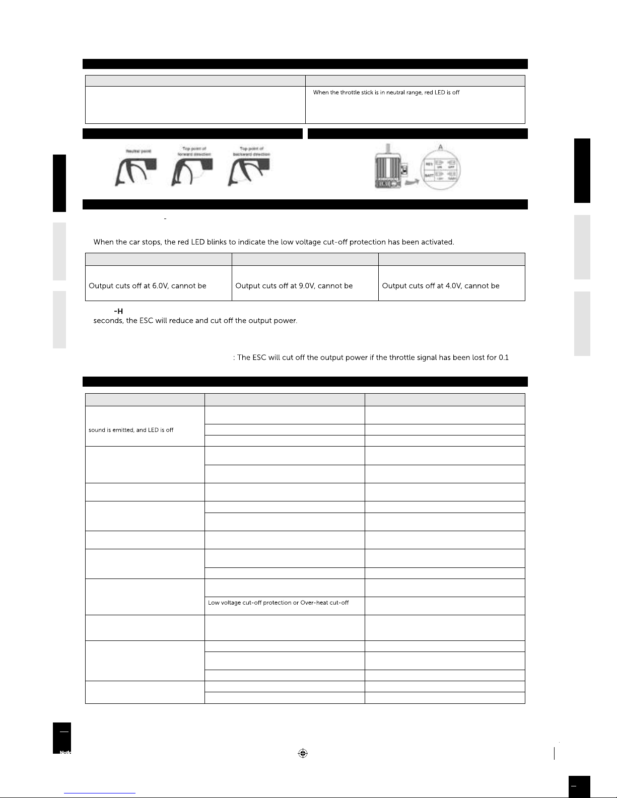
BEEP SOUND AND LED STATUS
The Meaning of Beep Sound LED Status
∞ 1 short Beep: The battery is NiMH/NiCd
∞ 2 short Beeps: The battery is 2S Lipo
∞ 3 short Beeps: The battery is 3S Lipo
∞ 1 long Beep: Self-test and throttle calibration is OK, the ESC is ready to run
∞
∞ Forward, brake or reverse at partial throttle, red LED blinks
∞ Forward, brake or reverse at full throttle, red LED is solid
THROTTLE SET THE ESC
PROTECTION FUNCTIONS
1. WOL VOLTAGE CUT OFF PROTECTION: If the voltage of battery pack is lower than the threshold for 2 seconds, the ESC will
enter the protection mode.
2S Lipo 3S Lipo 5-9 cells NiMH
Output reduces 50% at 6.5V
recovered
Output reduces 50% at 9.75V
recovered
Output reduces 50% at 4.5V
recovered
2. OVER
EAT PROTECTION: When the internal temperature of the ESC is higher than a factory preset threshold for 5
When the car stops, the red LED blinks to indicate the over-heat protection has been activated. If the ESC cools down to 80
Celsius degree, the output power is recovered to normal state.
3. THROTTLE SIGNAL LOSS PROTECTION
second.
TROUBLE SHOOTING
TROUBLE POSSIBLE REASON SOLUTION
After power on, motor can’t work, no
The ESC doesn’t get its working voltage; Connections
between battery pack and ESC are broken
Check the battery wires connection or replace the
defective connectors
Switch is damaged Replace the switch
Polarity or battery type is wrong Check polarity and battery type
After power on, motor can’t work; red
LED blinks
Throttle signal is abnormal
Check the throttle wire connection; make sure it is
plugged into the throttle channel of the receiver
Automatic throttle range calibration is failed
Set the “TRIM” of throttle channel to 0 or turn the knob
to its neutral position
The motor runs in the opposite direction
The wire connections between ESC and the motor need
to be changed
Swap two wire connections between the ESC and the
motor
The car can’t go backward
The jumper position is wrong Check the jumper and plug it to the correct position
The neutral point of throttle channel is changed or
drifted
Set the “TRIM” of throttle channel to 0 or turn the knob
to its neutral position
The car can’t go forward, but can go
backward
The direction of throttle channel is not correct
Reset the direction of throttle channel from original
“NOR” to “REV”, or from original “REV” to “NOR”
The motor doesn’t work, but the LED in
the ESC works normally
The connections between motor and ESC are broken
Check the connections and replace the defective
connectors
Motor is damaged Replace the motor
The motor suddenly stops running while
in working state
The throttle signal is lost
Check the transmitter and the receiver.
Check the throttle wire connection
protection has been activated
Replace the battery pack, or cool down the ESC
The car cannot get top speed and the red
LED doesn’t solid on at full throttle
Some setting in the transmitter are incorrect
Set D/R, EPA, ATL to 100% or turn the knobs to
maximum value.
Set TRIM to 0 or turn the knob to its neutral position
Motor is cogging when accelerated
quickly
The battery has limited discharge ability Use battery with better discharge ability
Motor RPM is too high, the gear ratio is too aggressive
Use motor with lower RPM, or use smaller pinion to get
softer gear ratio
Something wrong in the driving system of the car Check the driving system of the car
The car doesn’t run straight
Steering TRIM is not adjusted correctly Make adjustment of the TRIM
Wheel nuts are too loose Tighten wheel nuts
Notice 1/10ème-Multilingue.indd 10 08/11/13 15:20
Page 10

ENGLISHFRAN
Ç
AISDEUTSCH
10
GARANTIE DE 90 JOURS
MERCI DE LIRE ATTENTIVEMENT LES LIGNES CIDESSOUS :
A partir de la date d’achat, le produit est couvert par une garantie de 90 jours couvrant les composants. Si durant cette période, une des pièces composant votre
produit (hormis les pièces de transmission) possède un défaut de fabrication réellement constaté par notre service technique, la pièce sera réparée ou échangée.
Une fois cette nouvelle pièce utilisée, elle ne sera plus garantie.
Il est important de savoir que ce produite n’est en aucun cas un jouet, il est recommandé aux moins de 14 ans uniquement sous la surveillance d’un adulte. Il est de
la responsabilité des parents ou du tuteur de garantir que les moins de 14 ans ont une supervision nécessaire.
Lors de l’utilisation, si vous vous apercevez qu’il existe un problème avec le produit, il est de la responsabilité de l’acquéreur de rechercher et de corriger le
problème avant de causer des dommages plus importants.
NON GARANTIE
Ce produit est un modèle de haute performance et sophistiqué, il sera dans tous les cas traité avec soins et respect. Au niveau conception et choix des matières,
tout a été fait pour vous apporter un produit endurant et robuste. Toutefois, lors d’utilisation sévère et anormale, il est possible de casser et d’endommager les
pièces composantes le modèle.
La garantie ne couvre pas l’usure normale d’un produit ni la casse résultant de son utilisation. Elle ne s’applique pas non plus à la réparation de dommages
résultant d’une cause externe à l’appareil (par exemple d’un accident, d’un choc, de la foudre, de la tempête, de la présence d’eau (et plus généralement tous corps
étrangers à l’appareil, d’une fluctuation de courant, d’une oxydation…), d’une installation ou d’un branchement non conformes aux spécifications ou prescriptions
du constructeur, d’une utilisation nuisible à la bonne conservation de l’appareil, d’une utilisation à caractère professionnel, de l’utilisation de périphériques,
d’accessoires ou de consommables inadaptés, ou encore aux appareils démontés ou modifiés.
MISE EN PLACE DE LA GARANTIE
Dans un premier temps, veuillez retourner le produit chez votre revendeur, en tant que professionnel il vous conseillera sur la possibilité ou pas de la prise en
garantie.
Surtout, n’envoyez pas le produit directement chez le distributeur avant d’avoir vu votre revendeur et/ou sans l’accord du distributeur.
Vous n’avez pas à envoyer le produit en entier, seulement l’élément défectueux avec le formulaire qui vous sera transmis en amont. Dans tous les cas, ces frais
d’expédition sont à votre charge. Dans beaucoup de cas, il est plus rapide et rentable pour l’utilisateur de remplacer directement la pièce.
Attention, toute pièce retournée et inspectée par le service technique du distributeur qui ne s’avère pas prise en garantie, peut être sujette à des frais d’inspection,
de manipulation et de retour à votre charge. Si le produit défectueux demande une réparation et ne rentre pas dans les conditions couvertes par la garantie, ces
réparations vous seront facturées au prix horaire en cours applicable par le service technique du distributeur.
Si vous décidez de ne réaliser aucun travail de réparation, le distributeur se réserve le droit de facturer les frais d’inspection, de manipulation et d’expédition.
Nous vous conseillons de garder précieusement votre preuve d’achat, elle pourrait vous être utile.
ÉMETTEUR ET RÉCEPTEUR KONECT KT2S+
FCC ID: YDTHBT1000
FCC Statement : Cet équipement a été testé et déclaré conforme aux limites pour appareils numériques de section 15 des règlements de la FCC. Ces limites sont destinées à assurer une
protection raisonnable contre les interférences nuisibles dans une installation résidentielle.
Cet équipement produit, utilise et peut émettre de l’énergie radio électrique et, s’il n’est pas installé et utilisé conformément aux présentes instructions, peut causer des interférences nuisibles
aux communications radio.
Quoi qu’il en soit, on ne peut pas garantir que des interférences ne se produiront pas dans certaines installations. Si cet appareil cause des interférences nuisibles à la réception des signaux de
radio ou de télévision, ce qui peut être déterminé en allumant et en éteignant l’appareil, on encourage l’utilisateur d’essayer de corriger ces interférences par l’un des moyens suivants :
• Réorienter ou repositionner l’antenne de réception. • Augmenter la distance séparant l’équipement du récepteur.
• Branchez l’appareil sur un circuit électrique diérent de celui où le récepteur est branché.
Ce dispositif est conforme à la section 15 des réglementations de la FCC. Son fonctionnement est soumis aux deux conditions suivantes :
(1) Cet appareil ne doit pas causer d’interférences nuisibles,
(2) Cet appareil doit accepter toute autre interférence reçue, y compris les interférences pouvant entraîner un fonctionnement non désiré.
Note : Toute modification du dispositif peut annuler la capacité de l’acheteur à utiliser l’appareil.
DÉCLARATION DE CONFORMITÉ SELON LA DIRECTIVE R&TTE 1999/05/CE
Sarl Imodel
5 place de Rome
13006 Marseille
France
Declare que le produit suivant : 1.SL.BX8.RUNNER-G / O
w/ KONECT KT2S+ Transmitter & Receiver
Item Number: KN-KT2S-PLUS/SET
Catégorie d’équipement : 1
Correspond aux exigencies essenttieles de la directive FTEG (Article 3 de la directive R&TTE)
• Protection de la santé et de la sécurité de l’utilisateur et de toute autre personne
conformément à l’article 3.1.a
Norme appliqué : EN 62311:2008
• Exigence en matière de protection en rapport à la compatibilité électromagnétique
(article 3.1b)
Normes appliquées : EN 301 489-1 V1.9.2 (2011-09)
EN 301 489-3 V1.4.1 (2002-08)
• Utilisation ecace du spectre attribué aux communications radio terrestres ou spatiales
ainsi que les ressources orbitales pour éviter les interférences dommageables (article 3.2).
Normes appliquées: EN 300 440-1 V1.6.1 (2010-08)
EN 300 440-1 V1.4.1 (2010-08)
Adresse du fabricant : Sarl Imodel
5 place de Rome
13006 Marseille
France
Date de délivrance : 27 septembre 2012
Ce pictogramme indique que le produit ne doit pas être traité
comme déchet ménager. Vous devez veiller à éliminer ce produit
correctement afin d’éviter toute atteinte à l’environnement
et à la santé humaine. Un traitement ou une mise au rebut
inappropriés de ce produit pourraient avoir des conséquences
négatives sur l’environnement et la santé humaine. Aidez-nous
à respecter l’environnement !
i.A.
Page 11

ENGLISHFRAN
Ç
AISDEUTSCH
11
IMPORTANT LIRE AVANT DE DÉMARRER
LIRE CES INSTRUCTIONS ET SE FAMILIARISER AVEC LE PRODUIT AVANT DE S’EN SERVIR.
Ce produit n’est pas un jouet. C’est un modèle réduit de haute performance. Il est important de se familiariser avec le modèle,
son manuel et sa construction avant l’assemblage et le fonctionnement. La surveillance d’un adulte est nécessaire.
ATTENTION
Afin d’éviter tout dommage à des personnes ou à des biens, utiliser le modèle radio-commandé de manière responsable
comme décrit ci-après. Les modèles radio commandés peuvent atteindre des vitesses supérieures à 40km/h (25mph) et ne
peuvent s’arrêter instantanément.
❶ Ne jamais conduire le modèle radio-commandé sur les routes et dans les rues car il pourrait provoquer des accidents qui
causeraient de graves dommages.
❷ Ne pas rouler près de personnes ou d’animaux. Ne pas utiliser les personnes ou animaux comme obstacles.
❸ Pour éviter tout dommage aux personnes et animaux, ne pas conduire dans un endroit bruyant ou trop exigu.
❹ Piloter le modèle radio-commandé à l’intérieur entre des objets statiques peut causer des dommages aux objets et au
modèle radio-commandé.
PRÉCAUTIONS À OBSERVER PENDANT L’UTILISATION
Lorsque le modèle R/C est en marche, ne jamais toucher les parties en mouvement (transmission, roues, engrenages…)
❶ Quand le modèle roule, son moteur fonctionne continuellement et il chaue. Il peut atteindre une température élevée.
Ne pas le toucher, risque de brûlures. Faire Attention !
❷ S’assurer que personne n’utilise la même fréquence. Si c’est le cas, le contrôle du modèle risque d’être perdu et causer des
accidents.
❸ Préserver tous les fils des frottements et des pièces en rotation. Veiller à ce que les connecteurs soient bien enfichés et les
sécuriser avec la gaine thermorétractable ou de la bande adhésive d’isolation. Fixer les câbles au châssis avec des colliers en
nylon. Réparer immédiatement les fils et les connexions endommagés.
❹ Le moteur risque d’être endommagé si toutes les pièces en mouvement ne tournent pas librement : roues, axes de
transmission, pignonnerie…Le moteur risque de chauer plus que la normale, il consommera plus d’énergie et diminuera
l’autonomie de l’accu. Il est important de vérifier régulièrement que toutes ces pièces et le moteur sont en bon état.
Dans le cas contraire, les changer immédiatement.
❺ Si l’accu devient trop faible pour alimenter le récepteur, le contrôle du modèle est perdu. Arrêter le modèle quand il
commence à ralentir pour éviter de perdre le contrôle.
CONSIGNES DE SÉCURITÉ
- Ne pas faire fonctionner le modèle au milieu d’enfants ou de la foule.
- Vérifier que personne d’autre n’utilise la même fréquence dans le même secteur car cela pourrait provoquer de sérieux incidents.
- Ne pas rouler dans l’eau ou sous la pluie. Si le moteur, le dispositif électrique ou l’accumulateur est mouillé, le sécher immédiatement.
Ordre de fonctionnement fondamental du modèle sans fil:
Allumer l’émetteur après avoir mis le trim de gaz à la position neutre.
❷ Brancher le contact du récepteur.
❸ Avant de faire fonctionner, s’assurer du bon fonctionnement des 2 voies de votre émetteur.
❹ Régler le trim du volant, agir sur le curseur pour que le modèle puisse avancer droit.
❺ Après avoir arrêté de conduire, arrêter le récepteur et ensuite la radiocommande.
❻ Débrancher tous les accumulateurs.
❼ A la fin de chaque fonctionnement, nettoyer l’ensemble du modèle.
RÉGLAGES
Pour augmenter les performances du modèle, il est nécessaire de le régler en fonction de la surface et du tracé du circuit sur lequel il
roulera. Faire les réglages en se référant aux instructions de ce manuel.
Garder à l’esprit que « l’équilibre » est le maître mot.
❶ Pneus - Le pneu a une grande influence sur les performances de la voiture et sont normalement les premiers composants qu’il faut
modifier en fonction du circuit. Sélectionner les bons pneus pour le circuit où le modèle roulera en fonction de la surface et/ou des
conditions atmosphériques.
❷ Pincement et ouverture - Régler le modèle avec un peu de pincement procure un meilleur maintien du cap en ligne droite mais
diminue le rayon de braquage. L’ouverture procure une direction plus marquée et plus incisive, elle permet de tourner plus court.
Exagérer les modifications réduira les facultés du modèle.
❸ Carrossage positif & négatif - Lorsque le modèle tourne dans un virage, il subit la force centrifuge qui le pousse à l’extérieur du
virage, cela provoque une perte d’adhérence et de stabilité. La surface de contact de chaque pneu avec le sol est déterminée par l’angle
de carrossage. La traction des pneus peut être augmentée ou diminuée en modifiant le carrossage.
Pour augmenter l’adhérence dans les virages il faut augmenter le carrossage négatif. Pour réduire l’adhérence, augmenter le carrossage
positif.
❹ Garde au sol & débattement de la suspension - La garde au sol et le débattement des suspensions ont un eet direct sur la stabilité
en virage, accélération, freinage. La garde au sol peut être ajustée en modifiant la tension des ressorts des amortisseurs.
❺ Rapport de transmission - Le bon rapport de transmission est déterminé par la puissance du moteur + le type d’accu + les
conditions du circuit. Il est à noter que rouler sur un circuit avec une bonne adhérence suggère d’utiliser un pignon d’1 dent plus petite
afin d’utiliser toute la capacité de l’accu.
Page 12

ENGLISHFRAN
Ç
AISDEUTSCH
12
ÉMETTEUR
MANUEL D’UTILISATION
distribué par
Fonctions
Indicateur LED de batterie
Compartiment
porte-piles
ST.TRIM :
Trim de direction
Volant de
direction
Gâchette des gaz
TH.TRIM :
Trim gaz/frein
BIND (Synchronisation) /
EPA (Ajustement fin de course)
Antenne
Indicateur
de marche
ATV
POWER
ON / OFF
TH N-R :
Inversion gaz/frein
ST N-R :
Inversion de direction
Mise en place des piles
A
TTENTION
: Ne jamais essayer de démonter les piles ou de les jeter dans le
feu ou agents chimiques, ce qui pourrait provoquer des dommages
corporels ou des dégâts matériels.
Piles usagées: Respecter la réglementation en vigueur sur le traitement
des batteries usagées.
1. Après être tombées en panne, se débarasser des batteries usagées dans
les zones désignées loin de tout point d’eau, zone domestique et agricole.
2. Déposer les batteries usagées dans les points prévus à cet effet.
L’émetteur KT2S+
Volant de direction : Contrôle de la direction (Gauche/Droite) du
modèle
Gâchette des gaz :
Contrôle de la vitesse
(Marche avant / Frein / Marche arrière)
Compartiment porte-piles :
Maintient et couvre les piles qui
alimentent l’émetteur
Antenne : Transmet le signal au modèle
Power ON / OFF : Allume / Eteint l’émetteur
SYNC & indicateur de batterie :
La LED verte du haut indique le statut de
synchronisation et/ou l’alimentation
adéquate de la batterie
A
TV : Potentiomètre réglage fin de course
direction
S
T. Trim : Ajuste la position neutre du servo de
direction lorsque les roues du modèle sont
droites
TH.
Trim : Pour s’assurer que le modèle reste
immobile lorsque la gâchette des gaz est
relâchée
EPA électronique :
(End Point Adjusment = Ajustement des
fins de course)
Ajuste le débattement maximal des servos
de direction et de gaz/frein.
ATTENTION
: toute manipulation involontaire ou intentionnelle de
la fonction EPA peut entraîner des dysfonctionnements des
servos (débattement réduit ou nul dans certaines positions).
Merci de réinitialiser les valeurs maximales par défaut avant de
contacter votre revendeur. (voir «EPA», page 16)
Fonctionne avec 4 piles
1.5V AA ou batteries
rechargeables 1,2V AA (non
fournies), le KT2S+ peut
fonctionner plusieurs
heures.
Installation : Retirer le cache
du compartiment à piles
comme ci-dessous
Insérer les piles en
respectant les polarités
indiquées dans le
compartiment à piles
Remettre en place
le cache du
compartiment à
piles comme
indiqué ci-dessous
- Pendant une opération normale, la LED verte est allumée.
- Lorsque la tension descend sous 3.8V, la LED clignotera alternativement
Vert/Orange, pour indiquer que la batterie est faible. Remplacer les piles dès
que possible. ATTENTION : une batterie faible peut entraîner un dysfonctionnement du véhicule.
* Toujours allumer l’émetteur d’abord en faisant glisser l’interrupteur de bas
en haut. La lumière verte au-dessous de l’interrupteur doit s’allumer. Si ce
n’est pas le cas, vérifier que les piles ne soient pas usées, mal installées, ou
que la batterie ne soit pas déchargée.
1. Direction : Ajuster le Trim de direction
pour garder les roues avant en ligne
droite lorsque le volant de direction reste
en position neutre.
2. Gaz / Frein : Ajuster le Trim des gaz
pour s’assurer que les roues arrêtent de
tourner lorsque la gâchette des gaz reste
en position neutre (uniquement
thermique). Pour les véhicules
électriques, la position de la molette doit
être au neutre.
Vérification avant la mise en route
LED
indicator
LED
indicateur
ÉMETTEUR
MANUEL D’UTILISATION
distribué par
MÊME SI CE MODÈLE EST LIVRÉ PRÊT-À-ROULER, IL RESTE TOUT DE MÊME CERTAINES OPÉRATIONS À EFFECTUER, EN
PROFITER POUR SE FAMILIARISER AVEC VOTRE MODÈLE. SUIVRE LES ÉTAPES PAS À PAS.
Page 13

ENGLISHFRAN
Ç
AISDEUTSCH
13
Poser le véhicule sur un bloc pour éviter que les roues ne
touchent le sol.
A
Brancher la batterie au contrôleur à l’aide des connecteurs.
Vérifier que tous les composants câbles et électroniques
sont correctement installés.
Il est impératif de contrôler la correcte synchronisation entre
l’émetteur et le récepteur avant leur 1ère utilisation.
S’assurer que le Trim TH est au neutre.
ÉTEINDRE ÉMETTEUR ET VARIATEUR
B
Rester appuyé sur le bouton «BIND» du récepteur tout en
l’alimentant
C
.
Relâcher le bouton «BIND» lorsque la LED clignote en rouge.
Lorsque la LED rouge clignote, appuyer sur le bouton «BIND»
pour choisir sa fréquence de traitement. Si vous ne savez pas quel
type de servo vous utilisez, optez pour le clignotement lent.
ATTENTION : Ne pas sélectionner clignotement rapide pour
un servo analogique, il risquerait d’être endommagé.
- Clignotement rapide = fréquence rapide (7ms), pour le servo
digital
- Clignotement lent = fréquence lente (15ms), pour le servo
analogique
D
Rester appuyé sur le «BIND/EPA» de l’émetteur (1), puis
allumer l’émetteur (2), la LED clignote en vert : il communique
alors avec le récepteur. Relâcher le «BIND/EPA», lorsque la LED
du récepteur est rouge fixe, et celle de l’émetteur verte fixe,
l’appairage du récepteur avec l’émetteur est alors terminé.
CONTRÔLE ET APPAIRAGE DE LA RADIO (BIND)
COMMENT PILOTER VOTRE VÉHICULE
NEUTRE
1. Pousser la gâchette en arrière pour freiner le
véhicule ou partir en marche arrière
2. Appuyer sur la gâchette pour partir en marche avant
et accélérer
FREINS / DÉCÉLÉRATION /
MARCHE ARRIÈRE
ACCÉLÉRATION /
MARCHE AVANT
NEUTRE
Si les roues ne tournent pas dans le sens indiqué sur ce
schéma, changer la position du bouton de l’inversion de
servo (ST en postion NOR).
GAUCHE DROITE
A
C
B
D
(1)
(2)
Page 14

ENGLISHFRAN
Ç
AISDEUTSCH
14
AU SUJET DU SYSTÈME RADIO
L’inversion est utilisée pour inverser la commande du volant
de direction et de la gâchette des gaz.
L’émetteur KT2S+ possède deux fonctions d’inversion :
Inversion du sens du servo de direction et inversion du sens
du servo gaz/frein.
Inversion de direction : Inverse la réponse du volant de
direction.
En tournant le volant de direction vers la gauche, le modèle
tourne à droite, ou inversement.
Inversion des gaz/frein : Inverse la réponse de la commande
de la gâchette des gaz.
En accélérant avec la gachette des gaz, le modèle part en
marche arrière, ou inversement.
Le taux d’ajustement de direction permet d’ajuster le même angle maximum de direction des deux côtés (Gauche et Droite).
Il touche à la sensibilité du servo. Réduire la valeur de l’ATV peut baisser la sensibilité du servo et réduire l’angle maximum
de direction des deux côtés. Ne pas oublier d’ajuster la valeur de l’ATV dans la plage de réglage, rotation dans le sens horaire
augmente le pourcentage de braquage maximum. Rotation dans le sens inverse, diminue l’angle de braquage.
Le réglage minimum de l’ATV (en butée dans le sens anti-horaire) a pour eet un braquage nul à droite comme à gauche.
L’émetteur KT2S+ possède deux
fonctions de Trim :
Trim de direction et Trim des gaz.
Trim de direction : Ajuste la
position neutre du servo de
direction lorsque les roues sont
droites.
Normalement le Trim de direction
est ajusté jusqu’à ce que le
modèle puisse rouler droit.
Trim des gaz (modèle électrique = toujours au neutre) :
Ajuste la position neutre du servo des gaz. S’assurer que
le modèle reste immobile lorsque la gâchette des gaz est
relâchée (modèle thermique uniquement)
Inversion
Ajustement fin de course de direction
PROGRAMMATION ÉLECTRONIQUE DES FINS DE COURSE (EPA)
Pour éviter toute contrainte mécanique en butée de direction et/ou accélérateur et frein (pour le thermique), une fonction EPA
(End Point Adjusment = Ajustement des fins de course) est réglable électroniquement sur l’émetteur KT2S+. Pour la direction, il
est néanmoins possible d’éviter cette butée mécanique en utilisant la fonction ATV, laquelle diminuera la plage d’utilisation du
servo de direction, à gauche et à droite identiquement.
Si vous souhaitez réellement utiliser la fonction EPA, il est indispensable de lire attentivement et de bien comprendre son
fonctionnement décrit ci-dessous :
1. Servo de direction
a) Émetteur et récepteur sous tension (LED émetteur verte fixe), tournez et maintenez le volant en butée dans le sens dont
vous souhaitez régler la fin de course, puis restez appuyé 2 secondes sur «BIND/EPA» : la LED passe au rouge fixe.
b) Tant qu’elle reste rouge fixe, vous pouvez alors définir avec précision l’angle maximal de direction des roues du côté choisi.
Une fois l’angle du volant défini, appuyez de nouveau plus de 2 secondes sur «BIND/EPA». La LED clignote 2 fois vert clair/vert
foncé puis reste vert fixe.
Pour valider le réglage, éteignez et rallumez l’émetteur.
c) Pour réinitialiser la valeur maximale (par défaut), suivre l’opération a), puis dans l’opération b), maintenir le volant en butée
maximale et restez appuyé 2 secondes sur «BIND/EPA». La LED clignote 2 fois vert clair/vert foncé puis reste vert fixe.
Pour valider le réglage, éteignez et rallumez l’émetteur.
Pour le réglage du sens opposé, suivre les opérations a) et b) dans le sens opposé.
Il est très important d’eectuer ces opérations un côté après l’autre et de bien faire les 2 côtés.
2. Servo gaz/frein (l’EPA est conseillé uniquement pour les véhicules thermiques)
a) Émetteur et récepteur sous tension (LED émetteur verte fixe), accélérez en butée, puis restez appuyé 2 secondes sur «BIND/
EPA» : la LED passe au rouge fixe.
b) Tant qu’elle reste rouge fixe, vous pouvez alors définir avec précision la course maximale de la gâchette d’accélérateur.
Une fois la course définie, appuyez de nouveau plus de 2 secondes sur «BIND/EPA». La LED clignote 2 fois vert clair/vert foncé
puis reste vert fixe.
Pour valider le réglage, éteignez et rallumez l’émetteur.
c) Pour réinitialiser la valeur maximale (par défaut), suivre l’opération a), puis dans l’opération b), accélérez en butée et restez
appuyé 2 secondes sur «BIND/EPA». La LED clignote 2 fois vert clair/vert foncé puis reste vert fixe.
Pour valider le réglage, éteignez et rallumez l’émetteur.
Pour le réglage du frein, suivre les opérations a) et b) en freinant en butée et ajustez alors la course maximale de freinage.
Il est très important d’eectuer ces opérations un côté après l’autre et de bien faire les 2 côtés.
3
2
4
Réglages du neutre (Trim)
Page 15
ENGLISHFRAN
Ç
AISDEUTSCH
15
Ces variateurs haut de gamme spécifiques à la RC peuvent être très dangereux, nous recommandons de lire attentivement la
notice.
HobbytecH
ne possède aucun contrôle sur l’utilisation, l’installation ou la maintenance de ses produits et ne couvre pas
en garantie les dommages, les pertes et la mauvaise utilisation de celui-ci.
ATTENTION, TOUTE MODIFICATION DU PRODUIT (ex : SOUDURE, CHANGEMENT DE FILS, CHANGEMENT DU VENTILATEUR,
CHANGEMENT DE CONNECTEUR), ENTRAINERA UNE ANNULATION FERME ET IMMÉDIATE DE TOUTE PRISE EN CHARGE DE
NOTRE SERVICE APRÈS-VENTE.
CARACTÉRISTIQUES
1. Ne craint ni les éclaboussures ni la poussière.
2. Petit encombrement pour une forte puissance.
3. Calibrage des courses de gaz automatique, facile d’utilisation.
4. Diérentes protections : coupure de protection basse tension pour les batteries LiPo et NiMH,
protection contre la surchaue, contre les pertes radio.
5. Facile à programmer avec les ponts.
SPÉCIFICATIONS TECHNIQUES
Modèle KN-BRUSH40
Courant continu
Marche avant : 40A / 180A
Marche arrière : 20A / 90A
Voltage d’alimentation 2-3S Lipo, 5-9 cellules NiMH/NiCd
Type de voiture
1:10 on-road, o-road Buggy, Truggy, SCT
1:10 Crawler, Tank & Bateau
Limite du
moteur
2 Lipo
or 5-6 NiMH
540 or 550 ≥12T
RPM < 30000 @7.2V
3 Lipo
or 7-9 NiMH
Taille de moteur 540 ou 550 ≥18T
RPM < 20000 @7.2V
Résistance
Marche avant : 0.002 Ohm
Marche arrière : 0.004 Ohm
Entrée BEC 2A/5V (Mode linéaire BEC)
Fréquence PWM 1KHz
Dimensions, Poids 46.5*34*28.5, 65g
PREMIÈRE UTILISATION DU VARIATEUR
1. Brancher le variateur, le moteur, le récepteur, la batterie et le servo selon le schéma suivant :
Les fils “+” et “-” du variateur sont branchés au pack de
batterie.
ATTENTION : Une mauvaise polarité endommagera
immédiatement le variateur.
Le câble de contrôle du variateur (tricolore, noir, rouge
et blanc) est branché sur la voie des gaz du récepteur
(habituellement CH2).
Les câbles “Moteur +” and “Moteur –” sont branchés au
variateur sans ordre précis. Si le moteur tourne en sens
inverse, échanger les emplacements de ces 2 connexions.
2. Réglage de l’émetteur
Régler “D/R”, “EPA” and “ATL” à 100% pour la voie des gaz
(Pour les émetteurs sans écran LCD, tourner les boutons
jusqu’aux valeurs maximales), et régler “TRIM” de la voie
des gaz à 0 (Pour les émetteurs sans écran LCD, tourner le
bouton jusqu’à la valeur maximale).
Pour les émetteurs Futaba
TM
et similaires, la direction de la voie des gaz doit être réglée sur “REV”, alors que les autres systèmes
radio doivent l’être sur “NOR”.
La fonction “Fail Safe” du système radio est fortement recommandée. S’assurer que le moteur peut être arrêté lorsque le «Fail
Safe» se produit.
3. Calibrage du variateur (Calibrage des courses de gaz)
Pour être sûr que le variateur s’harmonise avec la plage des gaz des diérents émetteurs, le calibrage du variateur est
nécessaire.
Pour calibrer le variateur, allumer l’émetteur, laisser la gachette des gaz en position neutre et attendre 3 secondes pour laisser
le variateur s’auto-tester et eectuer un calibrage automatique. Lorsque le variateur est prêt à démarrer, le moteur émet un
long bip sonore.
Note : Le calibrage des courses de gaz s’eectue lors de la première utilisation du variateur, d’un nouvel émetteur ou lors d’un
changement de réglages du neutre, paramètres ATV et EPA. Sinon, le variateur ne peut fonctionner correctement.
VARIATEUR 40
amp
BRUSHED WATERPROOF - NOTICE
Page 16

ENGLISHFRAN
Ç
AISDEUTSCH
16
ALERTES SONORES ET STATUT DE LA LED
ALERTES SONORES STATUT DE LA LED
∞ 1 court bip sonore : la batterie est en NiMH/NiCd
∞ 2 courts bips sonores : la batterie est en 2S Lipo
∞ 3 courts bips sonores : la batterie est en 3S Lipo
∞ 1 long bip sonore : auto-test et calibrage OK, le variateur est prêt à démarrer
∞ Lorsque la gachette des gaz est en position neutre : la LED rouge est éteinte
∞ Marche avant, freinage ou marche arrière en position partielle : la LED rouge
clignote
∞ Marche avant, freinage ou marche arrière en position maximum : la LED rouge
est allumée
GACHETTE DES GAZ RÉGLAGE DU VARIATEUR
FONCTIONS DE PROTECTION
1. PROTECTION DE COUPURE DE TENSION MINIMALE : Si le voltage de la batterie est plus bas que le seuil minimum pendant
2 secondes, le variateur enclenchera le mode de protection.
Lorsque la voiture s’arrête, la LED rouge clignote pour indiquer que la coupure de tension minimale a été activée.
2S Lipo 3S Lipo 5-9 cells NiMH
À partir de 6.5V, puissance = 50%
Coupure définitive à 6.0V
À partir de 9.75V, puissance = 50%
Coupure définitive à 9.0V
À partir de 4.5V, puissance = 50%
Coupure définitive à 4.0V
2. PROTECTION THERMIQUE : Lorsque la température interne du variateur est plus élevée que le seuil prédéfini pendant 5
secondes, le variateur réduira puis coupera l’alimentation.
Lorsque la voiture s’arrête, la LED rouge clignote pour indiquer que la protection thermique a été activée. Si la température du
variateur redescend à 80° C, l’alimentation est rétablie à un état normal.
3. PROTECTION CONTRE LES PARTES RADIO : Le variateur coupera l’alimentation si le signal a été perdu pendant 0,1 seconde.
RÉSOLUTION DES PROBLÈMES
PROBLÈMES SOURCE DU PROBLÈME SOLUTION
Après mise sous tension, le moteur ne
fonctionne pas, aucun son n’est émis,
et la LED est éteinte
Le variateur ne reçoit pas sa tension de
fonctionnement ; Les connexions entre le pack
d’accus et le variateur ne sont pas correctes
Vérifier les connexions d’alimentation de la batterie ou remplacer
les prises
L’interrupteur est endommagé Remplacer l’interrupteur
Polarités ou type de batterie incorrect Vérifier la polarité et le type de batterie
Après mise sous tension, le moteur ne
fonctionne pas ; la LED rouge clignote
Le signal de la commande des gaz est anormal
Vérifier la connexion du câble de voie des gaz ; s’assurer qu’il est
bien branché sur le canal de voie des gaz du récepteur
Le calibrage automatique a échoué
Régler le “TRIM” de la voie des gaz sur 0 ou tourner le bouton sur
sa position neutre
Le moteur tourne en sens inverse
Les branchements entre le variateur et le moteur ne
sont pas corrects
Inverser les branchements entre le variateur et le moteur
La voiture ne peut pas reculer
La position du pont est mauvaise Vérifier le pont et le brancher dans la position adéquate
La position neutre de la voie des gaz est changée
ou dérivée
Régler le “TRIM” de la voie des gaz sur 0 ou tourner le bouton sur sa
position neutre
La voiture ne peut pas aller en marche
avant, mais peut reculer
La direction de la voie des gaz est incorrecte
Changer la direction de la voie des gaz de “NOR” sur “REV”, ou de
“REV” sur “NOR”
Le moteur ne fonctionne pas, mais la
LED du variateur est correcte
Les connexions entre le moteur et le variateur sont
rompues
Vérifier les connexions et remplacer celle qui sont défectueuses
Le moteur est endommagé Remplacer le moteur
Le moteur s’arrête subitement en plein
roulement
Le signal radio est perdu
Vérifier l’émetteur, le récepteur et la fixation de l’antenne
Vérifier la connexion du câble de voie des gaz
Protection de coupure de tension minimale ou
Protection thermique activée
Remplacer la batterie, ou refroidir le variateur
La voiture ne peut pas atteindre la
vitesse maximum et la LED rouge n’est
pas allumée en accélération maximum
Des réglages sur l’émetteur sont incorrects
Régler D/R, EPA, ATL à 100% ou tourner les boutons sur la valeur max.
Régler le TRIM sur 0 ou tourner le bouton sur la position neutre
Le moteur est irrégulier en accélération
maximale
La batterie a une capacité de décharge limitée Utiliser une batterie avec une meilleure capacité de décharge.
Le RPM du moteur est trop élevé,
le rapport d’engrenage est trop agressif
Utiliser un moteur avec un RPM plus bas, ou utiliser un pignon plus
petit pour obtenir un rapport d’engrenage plus doux
Quelque chose cloche dans le système de
transmission de la voiture
Vérifier le système de transmission de la voiture
Le modèle ne roule pas droit
Le TRIM de direction n’est pas correctement ajusté Ajuster correctement le TRIM
Les écrous de roue sont trop lâches Serrer les écrous de roue
Page 17

ENGLISHFRAN
Ç
AISDEUTSCH
17
GARANTIE UND SERVICE INFORMATIONEN
GARANTIEZEITRAUM DER KOMPONENTEN
BITTE LESEN SIE ERST DIE FOLGENDEN AUSFÜHRUNGEN !
Dies ist ein hochwertiges Hobby Produkt und kein Spielzeug. Daher ist es notwendig, daß Kinder unter 14 Jahren bei den
Gebrauch von einem Erziehungsberechtigten beaufsichtigt werden. Die Aufsichtspersonen und / oder Eltern haben die Pflicht
und Verantwortung die entsprechende Anleitung und Aufsicht an die minderjährige Person zu gewährleisten.
Diese Produkt hat eine 90 Tage Garantie, die nur dem Erstkäufer gewährleistet wird. Die Garantie gilt nur für die Produkte die
bei einem autorisierten Hobbytech Händler erworben wurden. Garantieansprüche werden nur mit einem gültigen Kaufbeleg
bearbeitet. Sollte innerhalb des Garantiezeitraumes ein Teil des Produktes infolge von Fabrikationsmängel ausfallen, dann liegt
es im ermessen von Hobbytech dies zu reparieren oder gegebenenfalls auszutauschen. Die Entscheidung zur Reparatur oder
zum Austausch liegt nur bei Hobbytech. Nach Benutzung bieten wir keine Neu für Alt Garantie.
GARANTIEAUSSCHLUSS
Dieses Hochleistungs-Modell wurde unter höchster Sorgfalt gefertigt und sollte mit Respekt behandelt werden. Von der
Garantie ausgeschlossen sind Komponenten die durch falschen Einbau, falsche Handhabung, Unfälle, Betrieb, Service,
mangelnde Wartung und Pflege, sowie Mißbrauch und / oder Reperaturversuche beschädigt wurden. Desweiteren sind auch
Verschleißteile wie etwa Sicherungen und Batterien, optische Beeinträchtigungen, Versand-, Transportkosten von der Garantie
ausgeschlossen.
GARANTIEANSPRUCH
Mit einem Garantieanspruch -, Reparaturen wenden Sie sich bitte an Ihren Fachhändler. Dieser wird sich mit Hobbytech
kurzschließen, um eine sachgerechte Entscheidung zu fällen, die Ihnen schnellst möglich hilft. Für ungültige
Garantieansprüche werden Ihnen vor der Rücksendung möglicherweise Bearbeitungskosten in Rechnung gestellt. Vorab
berechnet werden notwendige Reparaturen die durch Nachlässigkeit oder Mißbrauch erforderlich sind. Sollten Sie sich
entscheiden das keine Arbeiten ausgeführt werden sollen, behält sich Hobbytech das Recht Bearbeitungs und Versandkosten in
Rechnung zu stellen.
KONECT KT2S+
FCC ID: YDTHBT1000
FCC Statement: Dieses Gerät wurde getestet und entspricht den Grenzwerten für Teil 15 der FCC-Bestimmungen.
Diese Grenzwerte wurden entwickelt, zum angemessenen Schutz vor schädlichen Störungen bei einer Installation im Wohnbereich .
Dieses Gerät erzeugt und verwendet Hochfrequenzenergie und kann, wenn es nicht in Übereinstimmung mit den Anweisungen verwendet wird, Störungen im
Funkverkehr verursachen.
Es gibt jedoch keine Garantie, dass Störungen bei einer bestimmten Installation auftreten.
Wenn dieses Gerät schädliche Störungen bei Radio oder Fernsehempfang verursacht, das durch das Aus - Anschalten des Geräts festgestellt werden kann, dann
wird der Benutzer aufgefordert die Störungen durch eine oder mehrere der folgenden Maßnahmen zu korrigieren:
• Richten Sie die Empfangsantenne neu aus oder wechseln Sie den Standort.
• Erhöhen Sie den Abstand zwischen dem Gerät und dem Empfänger.
• Schließen Sie das Gerät an eine andere Steckdose als an dem der Empfänger angeschlossen ist.
Dieses Gerät entspricht Teil 15 der FCC-Bestimmungen. Der Betrieb unterliegt den folgenden zwei Bedingungen:
(1) Dieses Gerät darf keine Störungen verursachen, und
(2) Dieses Gerät muss jede empfangene Störung akzeptieren, einschließlich Störungen, die einen unerwünschten Betrieb verursachen können.
Hinweis: Änderungen an diesem Produkt wird die Berechtigung des Benutzers zum Betrieb dieses Geräts aufheben.
FCC-Erklärung:.
Konformitätserklärung gemäß dem Gesetz über Funkanlagen und
Telekommunikationsendeinrichtungen (R & TTE) Richtlinie 1999/5EC
sarl IModel
5 place de Rome
13006 Marseille
Frankreich
Erklärt das Produkt: 1.SL.BX8.RUNNER-G / O
w/ KONECT KT2S+
Artikel-Nr: KN-KT2S-PLUS/SET
Geräteklasse: 1
Entspricht den grundlegenden Anforderungen und den übrigen einschlägigen Bestimmungen des FTEG (Artikel 3
der R & TTE -Richtlinie)
• Schutz der Gesundheit und Sicherheit des Benutzers und jede andere Person, auf den
Schutz Anforderungen der Niederspannungsrichtlinie 73/23/EWG
(Artikel 3.1a der Richtlinie) basiert
Normen: EN 62311:2008
• Die grundlegenden Anforderungen der Richtlinie für elektromagnetische Verträglichkeit
(Artikel 3.1b )
Normen: EN 301 489-1 V1.9.2 (2011-09)
EN 301 489-3 V1.4.1 (2002-08)
• Eektive Nutzung des Frequenzspektrums / Orbital Ressource,
um Störungen zu vermeiden (Artikel 3.2).
Normen: EN 300 440-1 V1.6.1 (2010-08)
EN 300 440-1 V1.4.1 (2010-08)
Hersteller Adresse: Sarl Imodel
5 place de Rome
13006 Marseille
Frankreich
Datum der Ausstellung: Semptember 27, 2012
Dieses Produkt darf nicht über den Hausmüll
entsorgt werden.
Es ist die Verantwortung des Benutzers, die
Elektrogeräte am Ende der Laufzeit an einer
registrierten Rücknahmestelle für Elektroschrott
abzugeben.
Dies gewährleistet das die Umwelt und
natürliche Ressourcen geschont werden.
Für Fragen bezüglich der Müll Entsorgung
können Sie die zuständige Organisation oder
Ihren Fachhandel kontaktieren.
i.A.
Page 18

ENGLISHFRAN
Ç
AISDEUTSCH
18
WICHTIG LESEN SIE DIESE ANLEITUNG VOR DER VERWENDUNG DURCH !
BITTE LESEN SIE ALLE ANWEISUNGEN UND MACHEN SIE SICH MIT DEN PRODUKTEN VOR DER INBETRIEBNAHME VERTRAUT.
Dieses Produkt ist kein Spielzeug. Es ist ein hochentwickeltes Hobby Produkt. Es ist wichtig, sich mit dem Modell, dem Handbuch und
seiner Konstruktion vor der Montage und dem Betrieb vertraut zu machen. Die Beaufsichtigung durch Erwachsene ist erforderlich.
VORSICHT
Um ernsthafte Verletzungen und Sachschäden zu vermeiden, betreiben Sie alle ferngesteuerten Modelle in einer
ansprechenden Art und Weise wie nachfolgend beschrieben.
R/C Auto Modelle können Geschwindigkeiten von mehr als 40km/h (25mph) überschreiten und nicht schnell gestoppt werden.
❶
Niemals die R/C Modelle auf der Straße oder Autobahn fahren, da dies zu schweren Verkehrsunfällen beitragen und / oder führen könnte.
❷ Niemals ein R/C Modell in der Nähe von Menschen oder Tieren verwenden. Und / oder diese als Hindernisse verwenden,
wenn R/C Fahrzeuge betrieben werden.
❸ Um Verletzungen an Personen und / oder Tiere, sowie Schäden an Eigentum zu vermeiden, niemals ein R/C Modell in einem
begrenzten oder überfüllten Bereich betreiben.
❹
Bedienung von R/C Modelle auf Möbel oder andere leblose Gegenstände verursachen Schäden an den Objekten und den R/C Modell.
VORSICHT WÄHREND DES BETRIEBES
Wenn das R/C Modell in Betrieb ist, berühren Sie keinesfalls einer seiner beweglichen Teile, wie z.Bsp. Antriebswellen, Räder.
❶ Der Motor des Fahrzeuges wird sehr heiß während des Laufes und könnte bei Berührung Verbrennungen verursachen.
❷ Stellen Sie sicher, dass niemand in Ihrem Fahrbereich die gleiche Frequenz benutzt. Die Benutzung gleicher Frequenzen zur
gleichen Zeit, kann zu einem Verlust der Kontrolle über die R/C Modelle und somit zu schweren Unfällen führen. Egal ob Sie
Auto fahren, Fliegen oder Segeln.
❸ Stecker richtig verbinden. Um einen durch Kurzschluss entstandenen elektrischen Schlag und / oder Schäden am Produkt zu
verhindern, isolieren Sie Verbindungen mit Schrumpfschlauch oder Isolierband.
Vor der Inbetriebnahme des Fahrzeuges kontrollieren Sie die Batterie Verkabelung und Stecker und stellen Sie sicher das diese
nicht locker sind oder auf dem Boden schleifen. Sichern Sie die Leitungen mit Isolierband oder Nylon Kabelbinder.
❹
Steife Drehung der Zahnräder, Wellen, Gelenke und Räder können den Motor beschädigen oder zerstören. Bei der Montage wird
empfohlen, um eine ordnungsgemäße Verbindung und Drehung der Welle mit einer 1,5 V Trockenbatterie des Modells zu überprüfen. Ein
verschlissener Motor führt zum überhitzen und resultiert in kurze Laufzeit. Ersetzen Sie den abgenutzten Motor so schnell wie möglich.
❺ R/C Modelle können außer Kontrolle geraten, wenn die Batteriespanne vom Empfänger oder Sender abfällt. Bei Anzeigen
hierfür halten Sie das Fahrzeug sofort an, bevor Ihr Auto außer Kontrolle gerät.
SICHERHEITSHINWEISE
- Befolgen Sie die beschriebenen Vorschriften für einen sicheren Funksteuerungsbetrieb.
- Betreiben Sie Ihr Modell stets auf oenen Gelände, weitab von Automobilien, Verkehr und der Nähe von kleinen Kindern.
- Stellen Sie sicher, dass niemand in Ihrem Fahrbereich die gleiche Frequenz benutzt. Die Benutzung gleicher Frequenzen zur
gleichen Zeit kann zu schweren Unfällen führen, egal ob beim Autofahren, Fliegen oder Segeln.
- Vermeiden Sie das Fahren durch Pfützen und Regen. Wenn die R/C Einheit, der Motor oder der Akku nass geworden sind,
dann trocknen und säubern Sie diese in einem trocknen Bereich.
R/C Betriebsverfahren
❶ Sicherstellen, dass Kontrollsender und Trimm in neutral eingestellt sind. Sender einschalten.
❷ Empfänger einschalten.
❸ Überprüfen Sie den Betrieb des Sender vor der Inbetriebnahme.
❹ Stellen Sie Lenkservo und Trimm so ein, dass das Modell gerade läuft wenn der Sender in Neutral ist.
❺ Rückwärts-Sequenz zum Abschluss nach dem Laufen.
❻ Achten Sie darauf, die Verbindungen zu trennen / entfernen Sie alle Batterien.
❼ Entfernen Sie Sand, Matsch, Schmutz usw.
❽ Lagern Sie das Auto und Akkus getrennt, wenn sie diese nicht benutzen
INBETRIEBNAHME DES MODELL
Zu Verbesserung der Gesamtleistung des Autos, ist es notwendig, das Fahrzeug auf die jeweilige Strecke (und deren
Oberflächenbeschaenheit) auf die Sie fahren, einzustellen. Nehmen Sie die Einstellung unter Bezugnahme der
Bedienungsanleitung vor. Beachten Sie das „Balance“ das Stichwort ist.
❶ Reifen - Reifen haben einen großen Einfluss auf die Leistung Ihres Autos, und sind in der Regel die ersten Komponenten die
abgestimmt werden. Wählen Sie jeweils die richtigen Reifen für die Rennstecke auf der Sie fahren.
❷ Vorspur und Nachspur - Das Einstellen der Vorspur (Toe-in), die Räder zeigen etwas nach innen, bietet dem Fahrzeug guten
Geradeauslauf und moderate Lenkeigenschaften. Nachspur (Toe-out), die Räder zeigen etwas nach außen, gibt scharfe und
klare Lenkung. Achten Sie darauf, nicht zu übertreiben.
❸ Sturzwinkel - Beim Nehmen der Kurve ist das Auto gezwungen nach außen zu gehen, was zu Instabilität führen kann. Die
Kontaktfläche eines jeden Reifens wird durch den Sturzwinkel bestimmt. Die Haftung der Reifen kann durch die Einstellung des
Sturzes beeinflusst werden. Um die Haftung bei Kurvenfahrt zu erhöhen, stellen Sie den Sturzwinkel negativ. Um die Haftung zu
reduzieren stellen Sie den Sturz positiv ein.
❹ Bodenfreiheit und Aufhängungsrückgang - Bodenfreiheit und / oder Rückfederungshub haben einen großen Einfluss auf die
Stabilität bei Kurvenfahrt, Beschleunigung und Bremsung. Bodenfreiheit kann durch Änderung der Dämpfer Federkraft und
Steifheit eingestellt werden.
❺ Getriebeübersetzung - Das richtige Übersetzungsverhältnis sollte durch die verfügbare Ausgangsleistung des Motors
bestimmt werden, die Art der Batterie, Streckenzustand und das Layout. Es sollte auch angemerkt werden, dass das Fahren des
Autos auf einer guten Grifläche, die Verwendung des Ritzel um einen Zahn kleiner nahe liegt, um so eektiv alle verfügbare
Batterieleistung zu nutzen.
Funktionen
Batterie-LED-Anzeige
Batterieinstallation
Achtung: Zerlegen Sie niemals Batterien oder legen Sie diese ins Feuer
oder Chemikalien. Dies könnte zu Verletzungen oder Sachschäden führen.
Batterieentsorgung: Beachten Sie die entsprechenden Vorschriften zur
Behandlung und Entsorgung der verwendeten Batterien.
1. 1. Nachdem die Batterien leer sind, verwahren Sie diese korrekt auf, weit
weg von Wasserversorgung, Haushaltsbereichen und Pflanzflächen.
2. Bringen Sie die leere verwendeten Batterien zu spezifischen Recyclings-
tationen
Der Sender KT2S +
Lenkrad : Steuert die Lenkrichtung (links/rechts) des
RC-Modells
Gashebel : Regelt die Geschwindigkeit & Fahrtrichtung
(Vorwärts/Bremse/Rückwärts) des
RC-Modells
Antenne : Sendesignal zum RC-Modell
Power ON / OFF : Power AN / AUS des Senders
SYNC und Batterie-Anzeige : LED zeigt Synchonisationsstatus und / oder
den Status der Stromversorgung an
Betriebsanzeige : LED signalisiert Power "AN"
ATV : Zur Einstellung des max. Lenkweges
ST. Trim Einstellung : Zum justieren des Geradeauslauf bei
neutraler Lenkradstellung
TH. Trim Einstellung : Zum justieren der neutralen Gasstellung
Batteriefach : Abdeckung und Halterung der Batterien für
die Stromversorgung des Senders
BIND / EPA : Taste um Empfänger und Fernsteuerung zu
verbinden, sowie zum Einstellen der EPA
Funktion auf Kanal 1 & 2
WARNING: Versehentliches oder vorsätzliches falsches Einstellen der EPA
(End-Punkt-Einstellung) Funktion, kann zu einer Fehlfunktion oder
Beschädigung der Servos führen. Reduzieren Sie daher immer den
maximalen Ausschlag, um den nicht benötigten Servoweg. Bevor Sie sich
an den Fachhandel wenden, stellen Sie bitte wieder die maximalen
Standartwerte ein (Sieh Seite 24, «EPA»).
Arbeitet mit 4x 1,5V AA
Batterien oder Akkus (nicht
enthalten), die KT2S+ kann
damit mehrere Stunden
betrieben werden.
Installation: Entnehmen Sie die
Batteriefachabdeckung wie
unten dargestellt
Legen Sie die Batterien
oder Akkus ein, achten
Sie dabei auf die
richtige Polarität.
Dann installieren Sie
die Batteriefachab-
deckung wie im Bild
unten gezeigt.
- Im normalen Betrieb sollte die LED Anzeige grün leuchten
- Wenn die Batteriespannung unter 3.8V abfällt, leuchtet die LED rot und
blinkt sehr langsam. Dies zeigt an das die Batterien schwach sind und
umgehend durch neue ersetzt werden sollten.
Immer zuerst den Sender einschalten, indem Sie den Schalter von unten
nach oben schieben, die Leucht-Anzeige über dem Schalter ist jetzt grün.
Falls dies nicht der Fall ist, überprüfen Sie ob die Batterien entladen sind
oder falsch eingelegt wurden
1. Lenkung: Stellen Sie den Trimm so
ein, so dass die Vorderräder in einer
geraden Linie stehen und das Lenkrad
in NEUTRAL-Position ist.
2. Gas / Bremse: Stellen Sie die
Trimmung so ein, dass die Räder sich
nicht drehen wenn der Gashebel auf
Neutral steht (nur bei Verbrenner /
Nitro Fahrzeugen).
Bei Elektromodellen sollte die
Trimmung auf NEUTRAL stehen.
Bevor Sie starten
LED
indicator
Indicator
LED
Batteriefach
ST. Trim Einstellung
Lenkrad
Gashebel
TH. Trim Einstellung
BIND/ EPA
Antenne
Betriebsanzeige
ATV
Power
ON / OFF
Umkehr Drehrichtung
Gas/Brems Servo
Umkehr Drehrichtung
Lenkservo
SENDER
BENUTZERHANDBUCH
Page 19

ENGLISHFRAN
Ç
AISDEUTSCH
19
Funktionen
Batterie-LED-Anzeige
Batterieinstallation
Achtung: Zerlegen Sie niemals Batterien oder legen Sie diese ins Feuer
oder Chemikalien. Dies könnte zu Verletzungen oder Sachschäden führen.
Batterieentsorgung: Beachten Sie die entsprechenden Vorschriften zur
Behandlung und Entsorgung der verwendeten Batterien.
1. 1. Nachdem die Batterien leer sind, verwahren Sie diese korrekt auf, weit
weg von Wasserversorgung, Haushaltsbereichen und Pflanzflächen.
2. Bringen Sie die leere verwendeten Batterien zu spezifischen Recyclings-
tationen
Der Sender KT2S +
Lenkrad : Steuert die Lenkrichtung (links/rechts) des
RC-Modells
Gashebel : Regelt die Geschwindigkeit & Fahrtrichtung
(Vorwärts/Bremse/Rückwärts) des
RC-Modells
Antenne : Sendesignal zum RC-Modell
Power ON / OFF : Power AN / AUS des Senders
SYNC und Batterie-Anzeige : LED zeigt Synchonisationsstatus und / oder
den Status der Stromversorgung an
Betriebsanzeige : LED signalisiert Power "AN"
ATV : Zur Einstellung des max. Lenkweges
ST. Trim Einstellung : Zum justieren des Geradeauslauf bei
neutraler Lenkradstellung
TH. Trim Einstellung : Zum justieren der neutralen Gasstellung
Batteriefach : Abdeckung und Halterung der Batterien für
die Stromversorgung des Senders
BIND / EPA : Taste um Empfänger und Fernsteuerung zu
verbinden, sowie zum Einstellen der EPA
Funktion auf Kanal 1 & 2
WARNING: Versehentliches oder vorsätzliches falsches Einstellen der EPA
(End-Punkt-Einstellung) Funktion, kann zu einer Fehlfunktion oder
Beschädigung der Servos führen. Reduzieren Sie daher immer den
maximalen Ausschlag, um den nicht benötigten Servoweg. Bevor Sie sich
an den Fachhandel wenden, stellen Sie bitte wieder die maximalen
Standartwerte ein (Sieh Seite 24, «EPA»).
Arbeitet mit 4x 1,5V AA
Batterien oder Akkus (nicht
enthalten), die KT2S+ kann
damit mehrere Stunden
betrieben werden.
Installation: Entnehmen Sie die
Batteriefachabdeckung wie
unten dargestellt
Legen Sie die Batterien
oder Akkus ein, achten
Sie dabei auf die
richtige Polarität.
Dann installieren Sie
die Batteriefachabdeckung wie im Bild
unten gezeigt.
- Im normalen Betrieb sollte die LED Anzeige grün leuchten
- Wenn die Batteriespannung unter 3.8V abfällt, leuchtet die LED rot und
blinkt sehr langsam. Dies zeigt an das die Batterien schwach sind und
umgehend durch neue ersetzt werden sollten.
Immer zuerst den Sender einschalten, indem Sie den Schalter von unten
nach oben schieben, die Leucht-Anzeige über dem Schalter ist jetzt grün.
Falls dies nicht der Fall ist, überprüfen Sie ob die Batterien entladen sind
oder falsch eingelegt wurden
1. Lenkung: Stellen Sie den Trimm so
ein, so dass die Vorderräder in einer
geraden Linie stehen und das Lenkrad
in NEUTRAL-Position ist.
2. Gas / Bremse: Stellen Sie die
Trimmung so ein, dass die Räder sich
nicht drehen wenn der Gashebel auf
Neutral steht (nur bei Verbrenner /
Nitro Fahrzeugen).
Bei Elektromodellen sollte die
Trimmung auf NEUTRAL stehen.
Bevor Sie starten
LED
indicator
Indicator
LED
Batteriefach
ST. Trim Einstellung
Lenkrad
Gashebel
TH. Trim Einstellung
BIND/ EPA
Antenne
Betriebsanzeige
ATV
Power
ON / OFF
Umkehr Drehrichtung
Gas/Brems Servo
Umkehr Drehrichtung
Lenkservo
SENDER
BENUTZERHANDBUCH
Page 20

ENGLISHFRAN
Ç
AISDEUTSCH
20
Stellen Sie das Fahrzeug auf einen Block, so das die Räder den
Boden nicht berühren.
A
Verbinden Sie den Akku zum Regler. Fixieren Sie die Kabel
richtig mit dem kleinen vorgesehenen Nylon Wrap.
Vor der Inbetriebnahme überprüfen Sie das Signal von
Sender und Empfänger.
Stellen Sie sicher das der TH Trim auf neutral ist.
SCHALTEN SIE DEN SENDER UND EMPFÄNGER AUS
B
Drücken und halten Sie die Setup-Taste am Receiver beim
Einschalten des Receivers
C
.
Lassen Sie die Setup-Taste los, wenn das LED grün blinkt.
Während das LED grüne blinkt, drücken Sie die Setup-Taste, um
die Bildfrequenz zu wählen.
- Schnelles blinken = hohe Bildfrequenz (7 ms) für digital Servo
- Langsamere blinkt = niedriger Bildfrequenz (15 ms), für analog
Servo.
D
Drücken und halten Sie die Setup-Taste des Sender und
schalten Sie den Sender ein. Der Sender kommuniziert mit dem
RX. Wenn das RX-LED fest leuchtet, ist der Kopplungsprozess
ausgeführt, und das RX ist mit dem TX gekoppelt.
EINSCHALTEN DER STROMVERSORGUNG (BIND)
STEUERUNG IHRES MODELLS (1)
NEUTRAL POSITION
1. Drücken Sie den Gashebel nach vorne um zu bremsen/rückwärts zu fahren
2. Ziehen Sie den Gashebel nach hinten um Gas zu geben
BREMSE /
SENKGESCHWINDIGKEITSPOSITION
VORWÄRTS /
BESCHLEUNIGUNGSPOSITION
STEUERUNG IHRES MODELLS (2)
Wenn die Räder in die entgegengesetzten Richtung arbeiten, dann bedienen Sie den Servo- rückwärts-Schalter (ST in NOR Position).
NEUTRAL
LINKS RECHTS
A
C
B
D
(1)
(2)
Page 21

ENGLISHFRAN
Ç
AISDEUTSCH
21
Umkehr
DAS FUNKSYSTEM
1
2
4
5
3
Einschalten der Stromversorgung (BIND)
Trimmen
Einstellbarer max. Lenkausschlag (ATV)
Wird verwendet um die Bewegungsrichtung
der Lenkung oder von Gas & Bremse zu
ändern.
Die KT2S+ Fernsteuerung verfügt über 2
Umkehrfunktionen:
Lenkung und Gas /
Bremse / Rückwärts.
Umkehr Lenkung
: Sie lenken nach rechts
aber das Model fährt nach links - dann
stellen Sie diesen Schalter um.
Umkehr Gas / Bremse / Rückwärts
: Sie geben Gas aber das Model Bremst
oder fährt rückwärts - dann stellen Sie diesen Schalter um.
Deinen Empfänger mit der KT2S+ Fernsteuerung verbinden
1. Schalten Sie Fernsteuerung und Empfänger aus.
2. Drücken und halten Sie den BIND Knopf am Empfänger gedrückt und
schalten Sie diesen ein.
3. Lassen Sie den BIND Knopf los wen die LED rot blinkt.
4. Während die LED rot blinkt, können Sie die Frame Rate mit dem BIND
Knopf verändern (kurzes drücken des Knopfes).
- Schnelleres blinken = höhere Frame Rate (7ms) / besser für digitale Servos
- Langsameres blinken = niedrigere Frame rate (15ms) / besser für analoge Servos
5. Drücken und halten Sie anschließend den BIND/EPA Knopf an der
Fernsteuerung gedrückt. Schalten Sie dann parallel die Fernsteuerung an.
Die LED sollte nun grün blinken und die Fernsteuerung kommuniziert mit
dem Empfänger. Lassen Sie den BIND/EPA Knopf los wenn die LED des
Empfängers dauerhaft rot leuchtet und die LED der Fernsteuerung grün. Nun
ist der Empfänger mit der Fernsteuerung verbunden.
Mit dem einstellbaren Lenkausschlag können Sie den maximalen Lenkweg
nach Links und Rechts vorgeben den das Servo machen soll, wenn Sie das
Lenkrad der Fernsteuerung ganz einschlagen. Diese Funktion beeinflusst auch
die Empfindlichkeit des Servos, so kann ein reduzieren des max. Lenkweges
die Empfindlichkeit des Servos heruntersetzen. Mit der ATV Einstellung wird
der maximale Lenkausschlag nach links und rechts gleichermaßen verändert.
Beachten Sie den max. Lenkausschlag nur innerhalb des maximal möglichen
mechanischen Lenkweges einzustellen. Im Uhrzeigersinn = erhöhen des max.
Lenkweges; gegen den Uhrzeigersinn = reduzieren des max. Lenkweges.
Die minimale Einstellung = maximal gegen den Uhrzeigersinn bedeutet
NULL-Lenkwinkel.
Der KT2S verfügt über zwei Trimmfunktionen:
Lenktrimm und Gastrimm.
Lenktrimm Einstellung:
Steuert die Neutralstellung des Lenkservos. Bei
Neutraler Lenkradstellung sollen auch die Räder neutral (gerade) stehen.
Im Betrieb sollte das RC-Modell bei neutraler Lenkradstellung geradeaus
fahren.
Normalerweise wird der Lenktrimm eingestellt, bis das Modell gerade
Strecken halten kann.
Lenktrimm Einstellung:
Steuert die Neutralstellung des Lenkservos. Bei
Neutraler Lenkradstellung sollen auch die Räder neutral (gerade) stehen.
Im Betrieb sollte das RC-Modell bei neutraler Lenkradstellung geradeaus
fahren.
End Punkt Einstellung (EPA)
Um mechanischen Stress beim Lenken, Gas geben oder Bremsen (Nitro / Verbrenner) zu vermeiden, kann ein digitaler Endpunkt (EPA) für die Servos gesetzt
werden. Bei der ATV Funktion kann dies zwar auch für die Lenkung gemacht werden, aber nur Links & Rechts gleichermaßen. Mit der EPA Funktion können Sie
dies für Links & Rechts unabhängig voneinander einstellen.
Wenn Sie die EPA Funktion nutzen wollen lesen Sie die folgende Anleitung sorgfältig:
1. Lenkservo
a) Fernsteuerung und Empfänger einschalten (Grüne LED leuchtet), drehen Sie das Lenkrad maximal in die Richtung welche Sie einstellen wollen. Halten Sie nun
den BIND/EPA Knopf für 2 Sekunden gerückt, nun sollte die LED rot leuchten.
b) So lange die rote LED leuchtet, können Sie den maximalen Lenkweg auf der Seite wählen die Sie einstellen möchten.
Haben Sie den gewünschten Lenkwinkel ausgemacht, drücken Sie erneut den BIND/EPA Knopf für 2 Sekunden. Die LED blinkt nun zwei Mal (hellgrün/dunkel
grün) und leuchtet anschließend dauerhaft grün
WICHTIG: Schalten Sie die Fernsteuerung Aus und wieder Ein, um die Einstellung zu bestätigen.
c) Um die Standardeinstellungen wiederherzustellen, folgen Sie den Schritten a) und b). Drehen Sie das Lenkrad maximal nach Links bzw. Rechts und drücken
Sie dann für 2 Sekunden den BIND/EPA Knopf. Die LED blinkt nun zwei Mal (hellgrün/dunkel grün) und leuchtet anschließend dauerhaft grün.
WICHTIG: Schalten Sie die Fernsteuerung Aus und wieder Ein, um die Einstellung zu bestätigen.
Um die andere Lenkrichtung einzustellen wiederholen Sie die Schritte a) und b) nur eben in die gegengesetzte Richtung einlenken.
Es ist sehr wichtig, dass Sie diese Einstellung für beide Lenkrichtungen und nacheinander vornehmen, um Beschädigungen zu vermeiden.
2. Gas- & Bremsservo (EPA wird nur bei Verbrenner / Nitromodellen benötigt)
a) Fernsteuerung und Empfänger einschalten (Grüne LED leuchtet), halten Sie den Gashebel auf Vollgasstellung (max. gezogen). Halten Sie nun den BIND/EPA
Knopf für 2 Sekunden gerückt, nun sollte die LED rot leuchten.
b) So lange die rote LED leuchtet, können Sie den maximalen Gasweg wählen den Sie benötigen bzw. einstellen möchten.
Haben Sie die gewünschte Position ausgemacht, drücken Sie erneut den BIND/EPA Knopf für 2 Sekunden. Die LED blinkt nun zwei Mal (hellgrün/dunkel grün) und
leuchtet anschließend dauerhaft grün
WICHTIG: Schalten Sie die Fernsteuerung Aus und wieder Ein, um die Einstellung zu bestätigen.
c) Um die Standardeinstellungen wiederherzustellen, folgen Sie den Schritten a) und b). Bewegen Sie den Gashebel auf Vollgasstellung (max. gezogen) und
drücken Sie dann für 2 Sekunden den BIND/EPA Knopf. Die LED blinkt nun zwei Mal (hellgrün/dunkel grün) und leuchtet anschließend dauerhaft grün.
WICHTIG: Schalten Sie die Fernsteuerung Aus und wieder Ein, um die Einstellung zu bestätigen.
Um die maximale Bremskraft einzustellen wiederholen Sie die Schritte a) und b) nur dieses Mal den Gashebel in die gegengesetzte Richtung bewegen (max. gedrückt).
Es ist sehr wichtig das Sie diese Einstellung für beide Richtungen und nacheinander vornehmen, um Beschädigungen zu vermeiden.
3
2
4
Page 22

ENGLISHFRAN
Ç
AISDEUTSCH
22
Hoch-Leistungssysteme für RC Modelle können gefährlich sein, daher empfehlen wir Ihnen dringend diese Anleitung sorgfältig
durch zu lesen.
DA WIR KEINE KONTROLLE ÜBER DIE KORREKTE INSTALLATION, VERWENDUNG, ANWENDUNG UND / ODER WARTUNG
UNSERER PRODUKTE HABEN, ÜBERNEHMEN WIR KEINE HAFTUNG FÜR SCHÄDEN, VERLUSTE UND / ODER KOSTEN, DIE
SICH AUS DER FEHLERHAFTEN NUTZUNG DES PRODUKTES ABLEITEN.
EIGENSCHAFTEN
1. Wasser - und Staubfest fuer alle Wetter Rennen.
2. Kleine Größe mit eingebauten Kondensator -Modul.
3. Automatische Drossel Bereich Kalibrierung, einfach zu bedienen.
4. Mehrere Schutzfunktionen : Niederspannungs Abschaltschutz für Lipo oder NiMH Batterie / Überhitzungsschutz / Gas
Signal Verlustschutz.
5. Leicht programmiert mit den Jumper.
SPEZIFIKATIONEN
Modell KN-BRUSH40
Kont. / Burst Strom
Vorwärts: 40A / 180A
Rückwärts: 20A / 90A
Eingang 2-3S Lipo, 5-9 Zellen NiMH/NiCd
Verwenbare Autos
1:10 on-road, o-road Buggy, Truggy, SCT
1:10 Crawler, Tank & Boat
Motor
Limit
2 Lipo
oder 5-6 NiMH
540 oder 550 ≥12T
RPM < 30000 @7.2V
3 Lipo
oder 7-9 NiMH
540 or 550 motor ≥18T
RPM < 20000 @7.2V
Widerstand
Vorwärts: 0.002 Ohm
Rückwärts: 0.004 Ohm
Built-in BEC 2A/5V (Linear mode BEC)
PWM Frequenz 1KHz
Abmessung & Gewicht 46.5*34*28.5, 65g
BEGINNEN ZU VERWENDEN
1. Verbinden Sie den Regler, Motor, Empfänger, Batterie und Servo nach dem folgenden Schema:
“+” und “-” Kabel des Reglers sind mit dem Akku Pack
verbunden.
ACHTUNG: Die falsche Polarität wird Ihren Regler sofort
beschädigen.
Das Kontrollkabel des Reglers (Trio Draht mit schwarz,
rot und weißer Farbe) ist zum Gaskanal des Empfängers
verbunden (meist CH2).
Der “Motor +” und “Motor –” Draht ist an den Regler
gebunden ohne feste Reihenfolge. Wenn der Motor in die
entgegengesetzte Richtung läuft, dann tauschen Sie bitte
die zwei Anschlüße.
2. Einstellen des Senders
Bitte stellen für den Gaskanal die “D/R”, “EPA” und “ATL” auf
100% (für Sender ohne LCD drehen Sie den Knopf auf den
maximalen Wert), und stellen Sie “TRIM” des Gaskanals auf
0 (für Sender ohne LCD drehen Sie den TRIM Knopf auf
neutrale Position).
Für FutabaTM und ähnliche Sender sollte die Richtung des Gaskanals auf “REV” eingestellt sein, während andere Sender
Systeme auf “NOR” eingestellt sind.
Es wird dringend empfohlen die “Fail Save” Funktion des Senders zu aktivieren. Gewährleisten Sie bitte das der Motor gestoppt
werden kann, wenn der “Fail Save” geschieht.
3. Gasbereich Einstellung (Gasbereich Kalibrierung)
Die Kalibrierung des Reglers ist notwendig, um den ESC übereinzustimmen mit den Gasbereich der verschiedenen Sender.
Um den Regler zu kalibrieren schalten Sie den Sender ein, halten Sie den Gasknüppel in der neutralen Position. Warten Sie
3 Sekunden so das der Regler den Selbsttest und automatische Gas Kalibritation ausführen kann. Wenn der Regler fertig ist,
erklinkt ein ein langer BEEP Ton vom Motor aus.
Hinweis: Bitte kalibrieren Sie die Gasbereiche erneut, wenn Sie einen neuen Sender nutzen oder die Einstellungen der neutralen
Position des Gaskanals, D/R, ATV, ATL oder EPA Parameter ändern, ansonsten kann der Regler nicht ordnungsgemäß funktionieren.
40AMP BRUSHED GESCHWINDIGKEITSREGLER / WASSERDICHT - BEDIENUNGSANLEITUNG
Page 23

ENGLISHFRAN
Ç
AISDEUTSCH
23
BEEP TÖNE UND LED STATUS
DIE BEDEUTUNG DER BEEP TÖNE LED STATUS
∞ 1 kurzer Beep: Die Batterie ist NiMH/NiCd
∞ 2 kurze Beeps: Die Batterie ist 2S Lipo
∞ 3 kurze Beeps: Die Batterie ist 3S Lipo
∞ 1 langer Beep: Selbsttest und Gaskalibrierung sind in Ordnung, der ESC ist fahrbereit
∞ Wenn der Gasknüppel im neutralen Bereich ist, ist das rote LED aus
∞ Vorwärts, Bremse oder rückwärts auf halben Gas, das rote LED blinkt
∞ Vorwärts, Bremse oder rückwärts auf vollen Gas, das rote LED ist solide
GASKNÜPPEL POSITION EINSTELLEN DES ESC
SCHUTZFUNKTIONEN
1. NIEDERSPANNUNGS ABSCHALTSCHUTZ: Wenn die Spannung niedriger ist als 2 Sekunden des Schwellenwertes, dan wird
der Schutz aktiviert.
Wenn das Auto stoppt, dann leuchtet das rote LED als Anzeichen das der Niedrigspannunsschutz aktief ist.
2S Lipo 3S Lipo 5-9 cells NiMH
Ausgang reduziert 50% bei 6.5V
Ausgang Abschaltung bei 6.0V
Ausgang reduziert 50% bei 9.75V%
Ausgang Abschaltung bei 9.0V
Ausgang reduziert 50% bei 4.5V
Ausgang Abschaltung bei 4.0V
2. ÜBERHITZUNGSSCHUTZ : Wenn die innere Temperatur des Reglers höher ist, als der vom Werk eingestellte Schwellenwert
für 5 Sekunden, dann wird der Regler die Ausgangsleistung verringern und abschalten.
Wenn das Auto stoppt, blinkt das rote LED als Anzeichen das der Überhitzungsschutz aktiviert ist. Wenn der Regler abkühlt auf 80
Grad Celsius ist die Ausgangsleistung auf normalen Stand herstellt.
3. GAS SIGNAL VERLUSTSCHUTZ : Der Regler wird die Ausgangsleistung abschalten, sobald das Gassignal für 0,1 Sekunden
verloren ist.
FEHLERSUCHE
PROBLEM MÖGLICHE URSACHE LÖSUNG
Nach dem Einschalten, funktioniert der
Motor nicht, kein Ton ist hörbar und
das LED ist aus
Der Regler bekommt nicht die nötige Spannung;
Verbindung zwischen Batterie und Regler ist
unterbrochen
Überprüfen Sie die Batterie Anschlussdrähte oder ersetzen Sie die
defekten Anschlüsse
Schalter ist beschädigt Ersetzen Sie den Schalter
Polarités ou type de batterie incorrect Überprüfen Sie die Polarität und die Art der Batterie
Nach dem Einschalten, funktioniert der
Motor nicht, rotes LED blinkt
Gas Signal is abnormal
Kontrollieren Sie die Gaskabel verbindungen; gewährleisten Sie
das diese im Gaskanal des Empfängers stecken
Automatische Gasbereich Kalibrierung ist
gescheitert
Stellen Sie den “TRIM” des Gaskanals auf 0 oder drehen Sie den
Knopf auf die neutrale Position
Der Motor läuft in die
entgegengesetzte Richtung
Die Kabelverbindung zwischen Regler und Motor
muss gewechselt werden
Tauschen Sie die 2 Drahtverbindungen zwischen Regler und Motor
Das Auto kann nicht rückwärts fahren
Die Jumper Position ist falsch
Kontrollieren Sie den Jumper und stecken Sie diesen in die richtige Position
Der Neutrale Punkte des Gaskanals ist geändert or
treibt
Stellen Sie den «TRIM» von Gas-Kanal auf 0, oder drehen Sie den
Knopf IKT Neutralstellung um
Das Auto kann nicht vorwärts fahren
aber rückwärts
Die Richtung des Gaskanals ist nicht richtig
Stellen Sie die Richtung des Gaskanals neu vom original “NOR” auf
“REV”, oder vom original “REV” auf “NOR”
Der Motor funktioniert nicht aber das
LED des Reglers arbeitet normal
Die Verbindung zwischen Motor und Regler ist
unterbrochen
Kontrollieren Sie die Verbindungen und erstetzen Sie kaputte
Stecker
Motor ist beschädigt Ersetzen Sie den Motor
Der Motor läuft plötzlich nicht mehr,
obwohl dieser im funktionstüchtigen
Zustand ist
Das Gas Signal ist verloren
Kontrollieren Sie den Sender und den Empfänger, sowie die
Gaskabel Verbindung
Niedrigspannungsabschaltungsschutz oder
Überhitzungsschutz ist aktiviert
Ersetze den Akku Pack oder lassen Sie den Regler abkühlen
Das Auto erreicht nicht die
Spitzengeschwindigkeit und das rote
LED ist nicht solide bei Vollgas
Einige Instellungen im Sender sind nicht richtig
Stellen Sie D/R, EPA, ATL auf 100% oder drehen Sie den Knopf auf
den maximalen Wert
Stellen Sie TRIM auf 0 oder drehen Sie den Knopf auf die neutral
Position
Motor stottert wenn schnell
beschleunigt wird
Die Batterie hat begrenzte Entlad Fähigkeit Benutzen Sie eine Batterie mit besserer Entladbarkeit
Motor RPM (Drehzahl) ist zu hoch.
Übersetzungsverhältniss ist zu aggressiv
Benutzen Sie einen Motor mit weniger Drehzahl oder nutzen Sie
kleinere Ritzel für ein geschmeidiges Übersetzungsverhältniss
Etwas ist falsch im Antriebssystem des Autos Kontrollieren Sie das Antriebssystem des Autos
Das Modell funktioniert nicht richtig
TRIM-Management ist nicht richtig eingestellt Passen Sie den TRIM an
Die Radmuttern sind zu locker Ziehen Sie die Radmuttern an
Page 24

24
NOTES
Page 25

25
GUIDE DE RÉFÉRENCE / REFERENCE GUIDE
RÉF. / ITEM
DÉSIGNATION / DESIGNATION
CA-271
Carrosserie BX8SL Runner Verte
BX8SL Runner Green body
CA-272
Carrosserie BX8SL Runner Orange
BX8SL Runner Orange body
CA-273
Aileron lexan BX8SL Runner Vert
Green BX8SL Runner prepainted wing
CA-274
Aileron lexan BX8SL Runner Orange
Orange BX8SL Runner prepainted wing
HT-458
Pneus MAXI CROSS montés collés sur jantes
blanches a bâtons
MAXI CROSS 1/8 Pre glued BUGGY Tyres on
white spokes wheels
HT-530005
Roulements 5x10x4 High speed ABEC5 x10pcs
High speed bearings 5x10x4 ABEC5 x10pcs
HT-570710
Amortisseurs avant SL en aluminium
SL front aluminium shocks
HT-570730
Amortisseurs arrières SL en aluminium
SL Rear aluminium shocks
KN-NI7.1800STICK
Batterie Ni-Mh Stick 7.2V 1800mAh
Stick 7.2V 1800mAh Ni-Mh battery
KN-KT2SPLUS/SET
Ensemble radio 2.4 GHZ Konect KT2S
2.4 GHZ Radio Konect KT2S
KN0612LVPL
Servo digital KONECT 6KG-0.12S pignons plastique
Digital servo KONECT 6KG-0.12S plastic gear
KN-BRUSH40
Variateur étanche brushed 40Amp 1/10 KONECT
ESC waterproof 40 Amp 1/10 brushed KONECT
KN-M55016T
Moteur électrique brushed KONECT 550 16T
550 brushed KONECT motor 16T
REV-003
Étrier avant gauche et droite
L/R Front C-hub
REV-004
Axe Étriers
C-Hub Pin
REV-011
Axe amortisseur avant
Front shock shaft
REV-014
Entretoise Sup d’amortisseur
Shock cap bushing
REV-015
Axes de sauve servo
Steering servo saver post
REV-016
Canons de bras de sauve servo
Servo saver arm bushing
REV-024
Boule de chape
Ball stud
REV-026
Vis étrier avant
C-Hub Screw
REV-032
Pas inversé M3x44
Turnbuckle M3x44
REV-034
Ressort de sauve servo
Servo saver spring
REV-047
Étriers arrières
Rear Hub set
REV-059
Support de servo
Servo mount
REV-062
Support d’aileron
Wing mounts
REV-063
Palonnier de servo
Servo horn arm
REV-066
Fusée avant droite/gauche
Front L/F steering block
REV-072
Kit de roulements
Bearing set
REV-077
Support carrosserie
F/R body post
REV-079
Kit plastique de direction
Steering set
REV-080
Corps de sauve servo
Servo saver pipe
RÉF. / ITEM
DÉSIGNATION / DESIGNATION
REV-SL007
Clavettes d’hexagones de roues SL
SL wheel hub Pin
REV-SL009
Accouplement diff central SL
SL center diff drive couple
REV-SL011
Boules de guidage d’axe de triangle SL
SL lower hinge pin plastic ball
REV-SL012
Set de cales de triangles arrière SL
SL Rear to-in plate/Lower Susp arm
REV-SL013
Axes de triangles avants SL
SL Front lower Susp hinge pin
REV-SL014
Set de cales de triangles avant SL
SL Front to-in plate/Lower Susp arm
REV-SL015
Pare choc avant BX8L
BX8L Front Bumper
REV-SL016
Platine supérieure Hobbytech SL
Hobbytech SL upper plate
REV-SL017
Barre de direction Hobbyteh SL
Hobbytech SL Steering Plate
REV-SL018
Boules de fusées de direction SL
SL steering knuckle ball end
REV-SL018
Boules de fusées de direction SL
SL steering knuckle ball end
REV-SL019
Cardans avants complet BX8SL / RX8SL
BX8SL / RX8SL CVD front drive shaft
REV-SL022
Cardan central alu SL
SL aluminium Center Drive Shaft
REV-SL023
Support moteur et différentiel cantral SL
SL Aluminium motor and diff mount
REV-SL024
Support moteur SL xe au moteur
Hobbytech SL Motor Holder
REV-SL025
Capot de différentiel central SL
SL Center Diff. Support Plate
REV-SL026
Ressort amortisseur avant BX8SL / RX8SL
BX8SL /RX8SL front shock spring
REV-SL027
Ressort amortisseur arrière BX8SL/RX8SL/B8SL
BX8SL /RX8SL / DB8SL Rear shock spring
REV-SL028
Axes de triangles arrières SL
SL Rear lower Susp hinge pin
REV-SL029
Molette d’amortisseur pour SL
SL Shocks adjustable Screw
REV-SL030
Membranes d’amortisseur Hobbytech SL
Hobbytech SL Shocks Bladders (4)
REV-SL031
Strap de batterie pour HOBBYTECH SL
HOBBYTECH SL Battery strap
REV-SL047
Cellule de diff à pignons av/ar pour DB8SL/BX8SL
DB8SL/BX8SL Pinion dff F/R Gearbox complety set
REV-SL051
Bouchon amortisseur aluminium 13mm
13 mm aluminium shocks cap
REV-SL052
Corps d’amortisseur ø13 L=49,5mm
BX8SL/DB8SL/BXR.MT Shock body ø13 L=49,5mm
REV-SL053
Corps d’amortisseur ø13 L=43mm
BXR.S1/MT/BX8SL Shock body ø13 L=43mm
REV-SL055
Piston amortisseur 13mm
13 mm Shock piston
REVSLOP05
Triangles avants/arrière SL
F/R lower suspension arm SL
STR-050TI
Écrous de roues Spirit EVO/NXT GP STR8/RG/
EVO/DELUXE EPX2
Wheel Nut Spirit EVO/NXT GP STR8/RG/EVO/
DELUXE EPX2
RÉF. / ITEM
DÉSIGNATION / DESIGNATION
REV-089
Écrou de sauve servo
Servo saver nut
REV-103
Rondelle calage Étrier arrière
Rear hub washer
REV-104
Rondelle calage triangle Ar
Rear arm washer
REV-115
Kit de joint amortisseur
Shock rebuilt kit
REV-117
Support amortisseur avant SURVOLT
Survolt Front Shock Tower
REV-119
Support amortisseur ar SURVOLT/ ST10
Rear shocks tower SURVOLT/ ST10
REV-122
Pas inversé avant carrossage ST10
Front Camber Turnbuckle ST10
REV-123
Pas inversé arrière carrossage ST10
Rear Camber Turnbuckle ST10
REV-129
Rehausse amortisseur ST10
ST10 shocks holder
REV-136
Axe amortisseur arrière ST10
ST10 Rear shock shaft
REV-140
Diff pignon noix de cardans av/ar
Pinion Diff Center F/R drive
REV-141
Diff pignon d’attaque 16Dts metal
Pinion Diff Metal Bevel Gear 16T
REV-142
Noix de cardans Diff Av/Ar
F/R diff drive cup set
REV-143
Couronne de différentiel
Differential bevel gear
REV-144
Joint torique de différentiel
Differential O-Ring
REV-145
Joints de différentiels
Differential Gaskets
REV-146
Pignons planétaires de différentiel
Diff Bevel gear 13T
REV-147
Bague de boitier de différentiel
Diff case bushing
REV-148
Pignons satellites de différentiel
10T Diff Bevel gear
REV-149
Axes des satellites du différentiel
Diff. Bevel Gear Shaft
REV-150
Corps de différentiel
Diff case
REV-153
Différentiel à pignon complet
Pinion Diff complety set
REV-154
Bagues supérieures de xation d’amortisseur
Shock cap bushing
REV-157
Nouvelles chapes avant/arrière/direction
New F/R/steering Ball Cups
REV-158
Boite étanche 1/10ème
Waterproof receiver box
REV-171
Maintien ressort chapes amortisseur BB
BB Shock bottom holder ball ends
REV-180
Pignon moteur 13 dts 32 Pitch
13T 32 Pitch pinion gear
REV-SL001
Châssis principal SL
Main chassis Hobbytech SL
REV-SL002
Couronne centrale 32 DP 56dts pour SL
32 Pitch Center Spur gear 56T spec SL
REV-SL003
Noix de diff central SL type I
SL center diff drive cup Type I
REV-SL004
Différentiel central SL complet
SL complety center differential
REV-SL005
Cardans arrières complet BX8SL / RX8SL
BX8SL / RX8SL CVD rear drive shaft
REV-SL006
Hexagones de roues 17mm BX8SL / RX8SL
BX8SL / RX8SL 17mm Wheel Hub
Page 26

26
O
P
T
I
O
N
A
L
REV-117
REV-011
REV-115
REV-136
REV-027
REV-171
HT-570710
HT-570730
REV-066
REV-129
HT-530005
REV-024
REV-016
STR-050TI
REV-034
REV-089
REV-080
REV-079
REV-079
REV-063
REV-104
REV-004
REV-158
REV-015
REV-141
REV-003
REV-059
REV-026
REV-004
REV-140
REV-014
REV-077
REV-157
REV-072
REV-SL016
REV-SL024
REV-180
REV-SL023
REV-SL055
REV-SL053
REV-SL051 REV-SL052
REV-SL027
REV-SL026
REV-SL029
KN-0612LVPL
KN-NI7.1800-STICK
REV-SL022
REV-SL018
REV-SL019
REV-SLOP05
REV-SL017
REV-SL018
REV-SL006
REV-SL007
REV-SL015
REV-SL014
REV-SL013
REV-SL011
REV-SL009
CA-271 (green)
CA-272 (orange)
CA-273 (green)
CA-274 (orange)
REV-154
KN-KT2S+/SET
Page 27
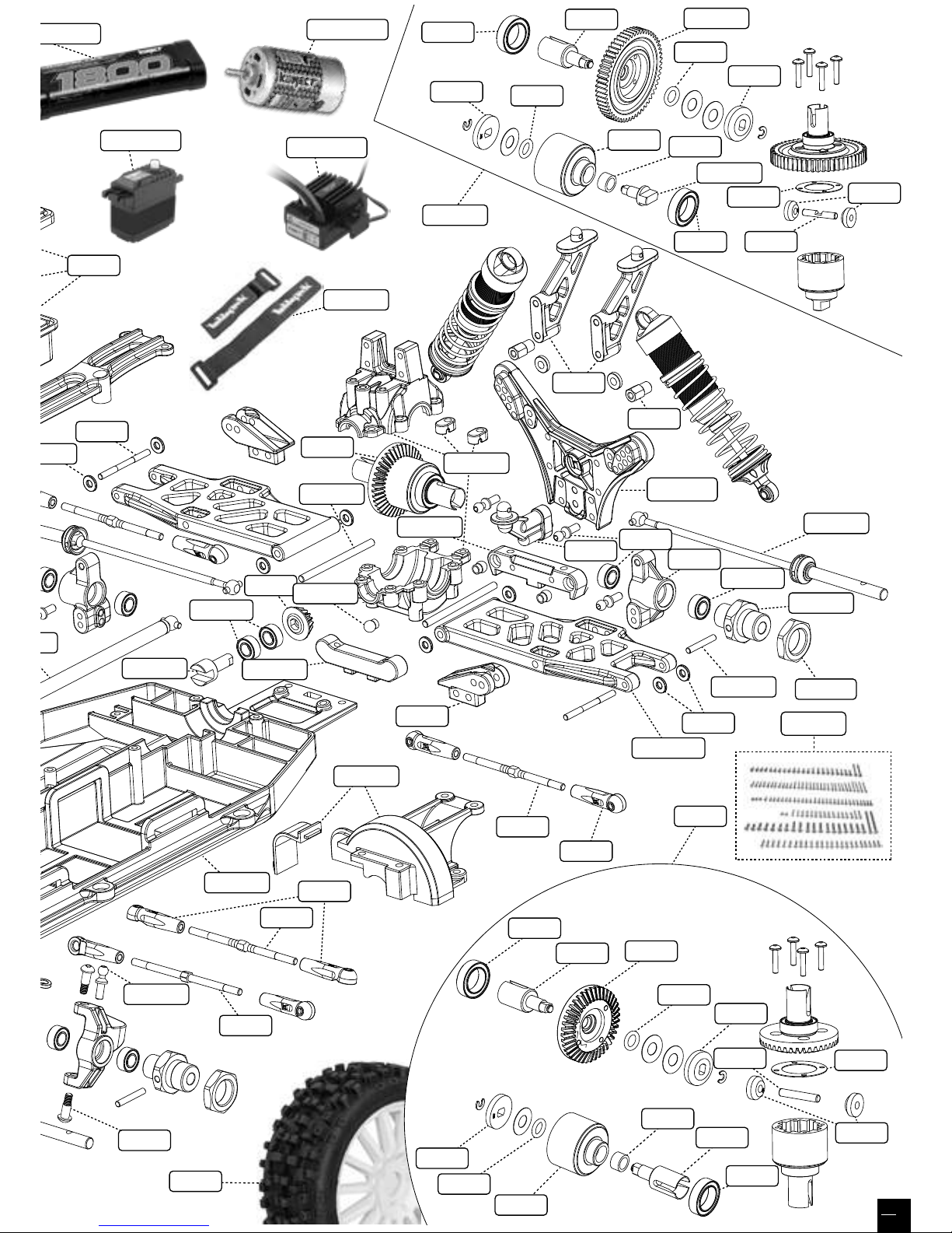
27
REV-119
STR-050TI
REV-004
REV-158
REV-014
REV-153
REV-077
REV-024
REV-047
HT-530005
HT-530005
REV-062
REV-SL047
REV-141
REV-129
REV-123
REV-026
HT-458
REV-157
REV-032
REV-122
REV-157
REV-072
REV-142
REV-143
REV-144
REV-146
REV-149
REV-145
REV-148
REV-147
REV-142
REV-072
REV-146
REV-144
REV-150
REV-153
REV-103
REV-072
REV-142
REV-144
REV-146
REV-149
REV-145
REV-148
REV-147
REV-SL003
REV-SL002
REV-SL004
KN-BRUSH40
KN-0612LVPL
KN-M550-16T
REV-SL031
REV-SL012
REV-SL007
REV-SLOP05
REV-SL006
REV-SL005
REV-SL011
REV-SL028
REV-SL012
REV-SL001
REV-SL018
REV-SL009
REV-SL025
REV-072
REV-146
REV-144
REV-150
REV-151
Page 28

REV-OP19
Kit de conversion complet diff pignon
Gear Diff Conversion set
REV-SLOP02
Support aluminium inférieur pour cellule avant
DB8SL/BX8SL
Aluminium Front toe-in plate DB8SL/BX8SL
HT-510035-RD
Palonnier alu direction rouge 25T
Steering alum servo horn red 25T
KN-LIPO.BAG
Housse de charge KONECT pour accus Lipo
Universal LiPo Battery safety bag KONECT
CA-264
Aileron transparent BX8SL Runner
BX8SL Runner clear wing
REV-OP25
Noix de cardans de diff. Avant ou arrière en acier
traité dur
Hard coated steel reinforced Front/Rear diffs. cups
REV-SLOP03
Cale anti-cabrage aluminium cellule arrière DB8SL/
BX8SL
Aluminium Rear susp arm Holder DB8SL/BX8SL
HT-504006
Sac porte voiture 1/8 Hobbytech
Hobbytech 1/8 car bag spec.
REV-SL032
Kit pare-chocs et éclairage BX8SL
BX8SL front bumper + light complety set
REV-SLOP04
Cale de pincement arrière DB8SL/BX8SL
Aluminium Reart toe-in plate DB8SL/BX8SL
REV-OP04
Fusées avants en aluminium
Aluminium front steering
REV-OP06
Étriers arrières en aluminium
Aluminium rear C-Hub
REV-OP16
Support d’amortisseur arrière en carbone
Carbon ber rear shock tower
REV-OP17
Set sauve servo en aluminium
Aluminium Servo saver set
REV-OP15
Support d’amortisseur avant en carbone
Carbon ber front shock tower
REV-OP05
Étriers avants en aluminium
Aluminium front C-Hub
KN-LP2S2200
Accu KONECT Li-Po 2200mAh 25C 2S1P (slim pack)
KONECT battery Li-Po 2200mAh 25C 2S1P (slim pack)
HT-504007
Sac Noir
Car Bag Black
Specification are subject to change without notice.
Photograph shows model after assembly and painting.
Les spécificités peuvent changer sans information préalable.
Les photos sont non contractuelles.
El fabricante puede modificar los kits sin previsio aviso.
Las fotos no son contractuales.
Spezifikation können ohne vorherige Ankündigung ändern.
Eektive Abbildung zeigt das Modell in Montage und Lackierung.
info@hobbytech-rc.com General information
OPTION PARTS & UPGRADES
REV-SLOP01
Support avant aluminium inférieur partie avant
DB8SL/BX8SL
Aluminium Front susp arm Holder DB8SL/BX8SL
REV-SLOP06
Renfort de cellule en alu pour DB8 / BX8 / BXR
DB8 / BX8 / BXR aluminium gear box spacer
KN-0913LVMG
Servo digital 9Kg-0.13S pignons métal
Digital Servo 9Kg-0.13S metal gear
KN-MULTIPEAK
Chargeur MultiPeak
MultiPeak charger
KN-ULTRAPEAK
Chargeur UltraPeak4
UltraPeak4 Charger
CA-270
Carrosserie transparente BX8SL Runner
BX8SL Runner clear body
 Loading...