

Page 1
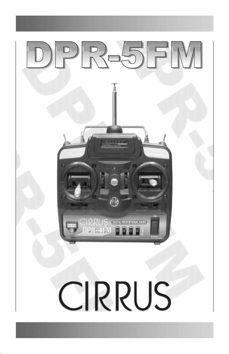
Digital Proportional 5 Channel FM Radio Control System
SYSTEM
OPERATING GUIDE
Page 2
INTRODUCTION
Thank you for purchasing the Cirrus DPR-5FM digital proportional radio control system.
The DPR-5FM is a high-quality, affordable 5 channel radio control system suitable for all
types of R/C aircraft, whether they be glow-powered or electric-powered. The DPR-5FM
radio control system is manufactured with high-quality solid-state components for long life
and reliability.
Please read and understand this System Operating Guide before using your DPR-5FM
radio control system.
FEATURES and LAYOUT
●
5 Channel 72Mhz FM Transmitter
●
Lightweight Design
●
Servo Reversing on Channels 1-4
●
Trainer System (Cord Not Included)
●
Transmitter Battery Voltage Meter
●
Audible Low Battery Alarm
●
Neck Strap Attachment
●
Adjustable Stick Length and Tension
8
15
13
16
17
18
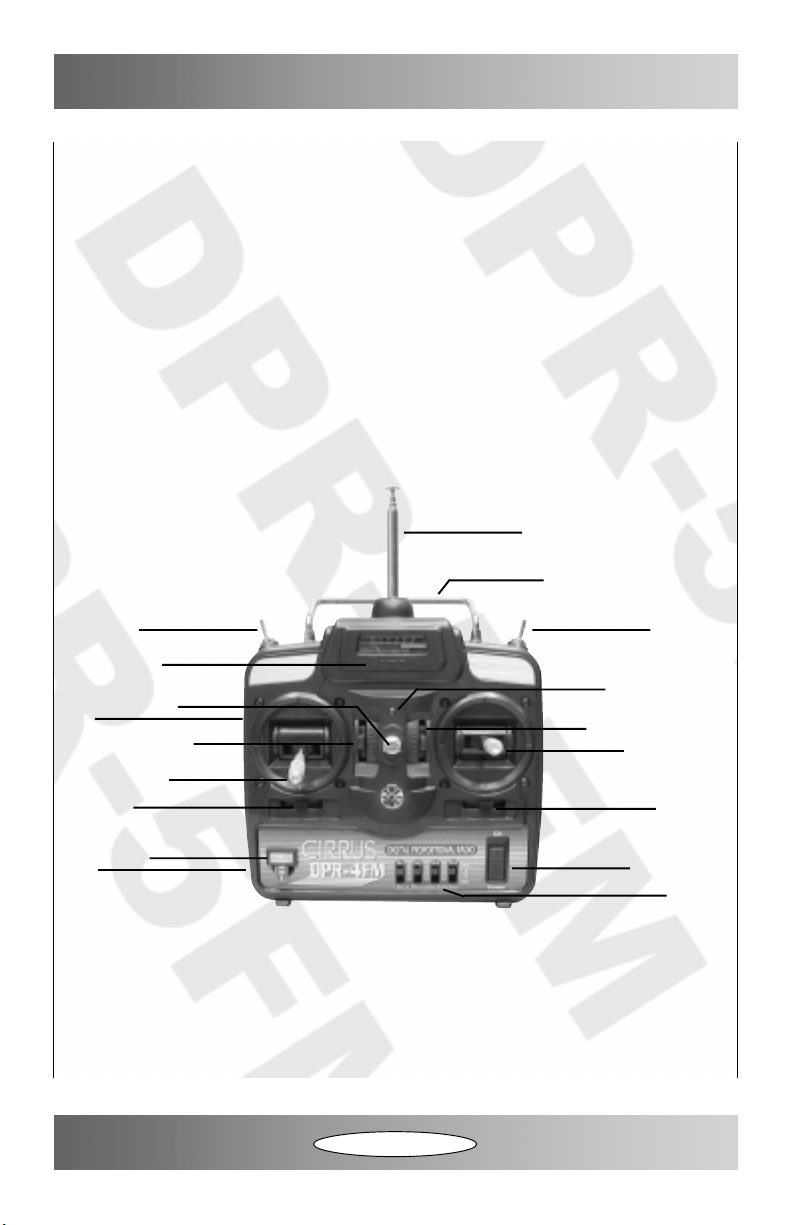
1 - Throttle/Rudder Control Stick
2 - Aileron/Elevator Control Stick
3 - Throttle Trim Lever
4 - Elevator Trim Lever
5 - Rudder Trim Lever
6 - Aileron Trim Lever
7 - Neck Strap Mount
8 - Antenna
9 - Power LED
7
3
1
11
14
9
4
2
65
10
12
10 - On/Off Switch
11 - Crystal
12 - Servo Reversing Switches
13 - Trainer Switch
14 - Auxiliary Switch (Retracts or Flaps)
15 - Carrying Handle
16 - Transmitter Battery Voltage Meter
17 - Trainer Jack (On Back)
18 - Battery Door (On Back)
2
Page 3

SAFETY PRECAUTIONS
●
Always perform a range check before each first flight of the day or after a particularly hard
landing, or after your radio control system has been repaired.
●
Check your airplane’s control surfaces before take off to ensure they are operating in the
correct direction.
●
Never fly your airplane from the street or at night. Always fly your airplane in a safe
manner and preferably at a dedicated R/C model flying site.
●
When the transmitter voltage meter enters the red portion of the scale, replace the
transmitter batteries with a fresh set. If you’re flying when this occurs, land immediately.
●
If the radio control system begins to glitch or act unusual, land immediately.
●
Before you fly, always check to make sure that your frequency is clear. Never turn on the
transmitter if someone else on your frequency is flying at the time. No two radio control
systems that are on the same frequency can operate nearby at the same time. If this occurs,
both pilots will lose control of their models. The frequency number is shown on the crystal
mount on the front of the transmitter. Listed below are the channel numbers and frequencies.
The Cirrus DPR-5FM radio control system operates on 72Mhz. The 72Mhz
frequency band is for AIRCRAFT USE ONLY. Listed below are the channel
numbers and frequencies that are available:
CH 11 FREQUENCY 72.010
CH 12 FREQUENCY 72.030
CH 13 FREQUENCY 72.050
CH 14 FREQUENCY 72.070
CH 15 FREQUENCY 72.090
CH 16 FREQUENCY 72.110
CH 17 FREQUENCY 72.130
CH 18 FREQUENCY 72.150
CH 19 FREQUENCY 72.170
CH 20 FREQUENCY 72.190
CH 21 FREQUENCY 72.210
CH 22 FREQUENCY 72.230
CH 23 FREQUENCY 72.250
CH 24 FREQUENCY 72.270
CH 25 FREQUENCY 72.290
CH 26 FREQUENCY 72.310
CH 27 FREQUENCY 72.330
CH 28 FREQUENCY 72.350
CH 29 FREQUENCY 72.370
CH 30 FREQUENCY 72.390
CH 31 FREQUENCY 72.410
CH 32 FREQUENCY 72.430
CH 33 FREQUENCY 72.450
CH 34 FREQUENCY 72.470
CH 35 FREQUENCY 72.490
CH 36 FREQUENCY 72.510
CH 37 FREQUENCY 72.530
CH 38 FREQUENCY 72.550
CH 39 FREQUENCY 72.570
CH 40 FREQUENCY 72.590
CH 41 FREQUENCY 72.610
CH 42 FREQUENCY 72.630
CH 43 FREQUENCY 72.650
CH 44 FREQUENCY 72.670
CH 45 FREQUENCY 72.690
CH 46 FREQUENCY 72.710
CH 47 FREQUENCY 72.730
CH 48 FREQUENCY 72.750
CH 49 FREQUENCY 72.770
CH 50 FREQUENCY 72.790
CH 51 FREQUENCY 72.810
CH 52 FREQUENCY 72.830
CH 53 FREQUENCY 72.850
CH 54 FREQUENCY 72.870
CH 55 FREQUENCY 72.890
CH 56 FREQUENCY 72.910
CH 57 FREQUENCY 72.930
CH 58 FREQUENCY 72.950
CH 59 FREQUENCY 72.970
CH 60 FREQUENCY 72.990
3
Page 4
FEATURES EXPLANATION
Trim Levers:
●
There is one trim lever associated with each primary function - throttle, rudder, elevator
and aileron. The trim levers are used to correct any tracking problems of the airplane and
the idle setting of the engine.
●
When you set up the control linkages on a new airplane, the control surface trim levers
should be centered. After flying and trimming the airplane, check the location of the control
surface trim levers. If one or more is no longer centered, we suggest making adjustments to
the airplane’s control linkages, so that the trim levers can be recentered.
Control Stick Length Adjustment:
●
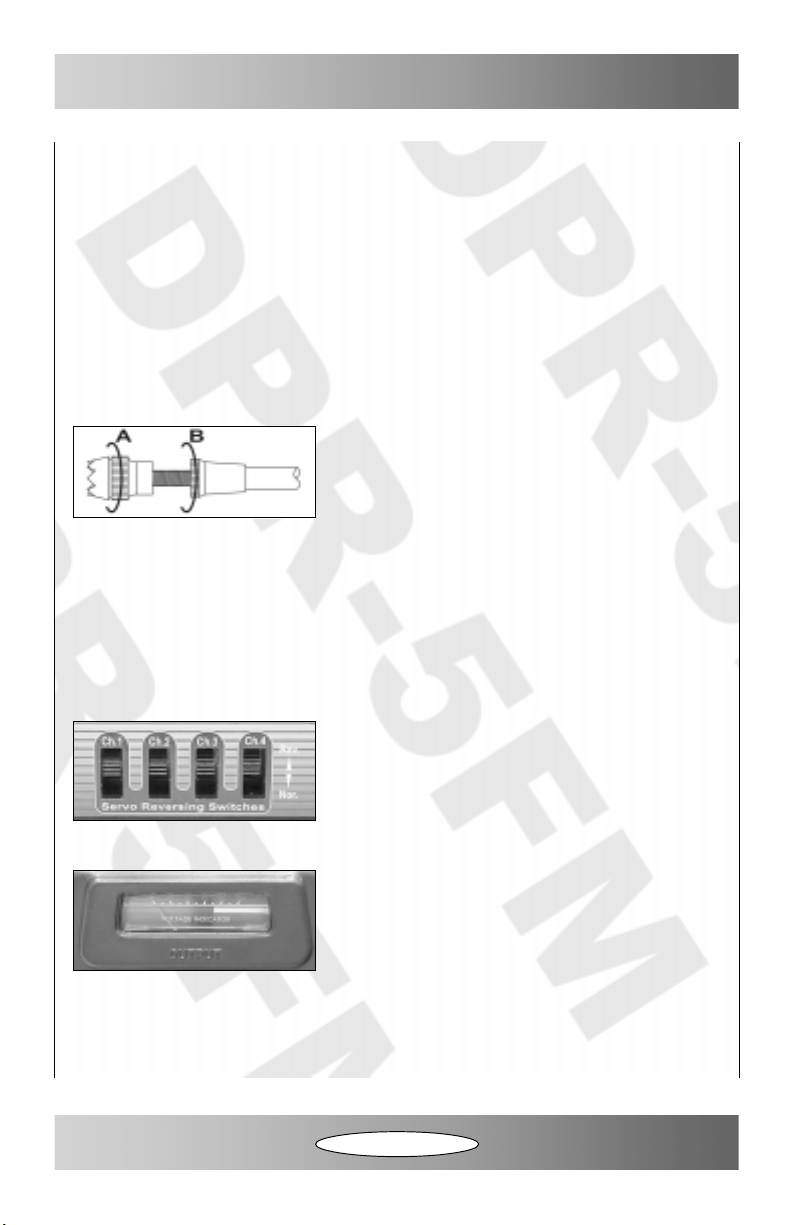
The length of the control sticks can be adjusted to suit
the user. When lengthening the control sticks, verify that
the ends of the control sticks are still firmly secured in
place. They should not be loose or they may come off.
Antenna:
●
The antenna is telescoping and should always be pulled out completely while flying.
Power LED:
●
The power LED glows red when the transmitter is turned on.
Servo Reversing Switches:
●
These switches allow you to electronically change the
direction the servos move. Servo reversing is featured
on channels 1-4. Double-check that each switch is firmly
pushed to one extreme or the other. A small flat-blade
screwdriver works well for moving the switches.
Transmitter Battery Voltage Meter:
●
When the transmitter is turned on, the voltage meter
displays the status of the transmitter batteries. If the
needle reads in the silver-colored area from 70-100, it’s
safe to fly. If the needle reads in the red-colored area,
the transmitter batteries should be replaced.
Auxiliary Switch:
●
The auxiliary switch will operate a servo plugged into the channel 5 slot of your receiver.
This switch is most often used for retractable landing gear or flaps. This switch can be used
for any function that requires a non-proportional action.
Continued On Next Page
4
Page 5
Control Stick Tension Adjustment:
●
The tension of the control sticks can be adjusted to suit the desired “feel” of the control
sticks in your hands.
●
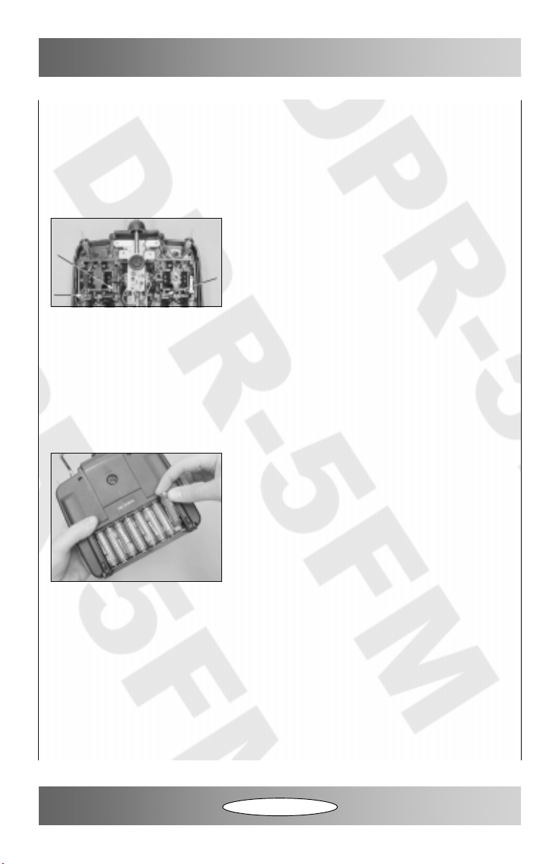
To adjust the control stick tension, begin by removing the four screws from the back of the
transmitter case. Next, carefully pull the back of the transmitter off and flip it back from the
bottom, so that the battery wires don’t get damaged.
●
Use a small phillips head screwdriver to adjust the
brass-colored screws directly above the spring pivot
joints on each gimbal. Turning the screws clockwise
increases the tension and turning the screws counterclockwise decreases the tension. Notice that the throttle
is a ratchet type and cannot be adjusted.
●
After adjusting the control stick tension, carefully reinstall the back of the transmitter,
making sure that no internal wires are pinched or otherwise damaged.
OPERATION
Installing the Batteries:
●
Remove the battery door from the back of the transmitter by pulling down on it with one
hand while holding the transmitter with your other hand.
●
Install 8 fresh “AA” Alkaline batteries, being careful to
make sure that the polarity is correct for each battery.
●
After double-checking that the batteries are installed
correctly, reinstall the battery door and turn on the
transmitter to verify that the voltage meter reads 100.
Range Check:
●
Range checking verifies that the transmitter is “talking” correctly to the receiver in your
airplane. A range check should be performed before the first flight of each day and after an
unusually hard landing, or after the radio control system has been repaired.
●
Perform the range check by walking away from the model with the antenna fully collapsed.
You should have normal control over the model up to 80 feet or more.
●
If the controls act erratically during the range check, DO NOT FLY until the problem has
been fixed.
Continued On Next Page
5
Page 6
Trainer System:
●
The trainer system allows two compatible transmitters to be linked together via a trainer
cable (available separately). This allows the student to control the model with the “student”
transmitter while allowing the instructor to take over at any time by releasing the trainer
switch on the “instructor” transmitter.
●
When using the trainer system, the DPR-5FM transmitter should be used as the
instructor transmitter.
●
The trainer cord plugs into the DIN socket on the back of the transmitter.
●
The student transmitter can be on a different frequency than the instructor transmitter,
although it must be FM or able to operate in PPM mode. The student transmitter should not
be turned on when operating the trainer system. Only the instructor transmitter should
be turned on.
●
When setting up the trainer system, it’s important that the student transmitter be set up
identical to the instructor transmitter. Verify that the trim levers and reversing switches are
set up the same. Also verify that the airplane’s controls work properly using BOTH
transmitters.
●
To activate the trainer system and give control to the student transmitter, pull back and
hold the trainer switch on the instructor transmitter. At this point, the student has control of
the airplane. If the student gets into trouble and the instructor needs to take over,
immediately release the trainer switch and control will revert to the instructor transmitter.
Using Optional NiCD Batteries and Charger:
●
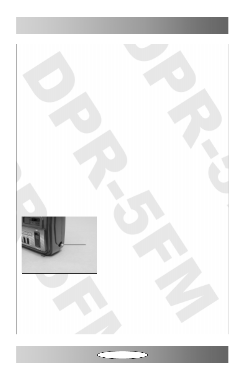
The transmitter features a charge jack in the right side
that allows you to charge NiCD batteries using a 110V
AC wall charger (available separately). This allows you
the option of using 1.2V NiCD cells in place of the 1.5V
“AA” Alkaline cells and being able to recharge them
inside the transmitter without having to put them in a
separate, special charger.
WARNING Never attempt to charge Alkaline cells. Doing so can cause the cells to catch
fire and/or explode, resulting in serious injury and/or property damage.
6
Page 7

FCC WARNINGS - PLEASE READ
Concerning Replacement of any transmitter component:
Replacement of any transmitter component (crystal, semiconductor, etc.) by the user
could result in a violation of the FCC rules. There are no internal adjustments of the
transmitter, and the user should not attempt to make any unauthorized changes.
Concerning Transmitter Repairs:
Any repairs that are deemed necessary should be done only by an authorized service
technician (Cirrus Radio Repair Department).Any repairs made by a non-authorized
person may result in a violation of FCC rules.
It is against FCC rules to modify this transmitter for any use other than that intended
by the manufacturer.
The Cirrus DPR-5FM radio control system is distributed exclusively by
All contents copyright © 2004, Global Hobby Distributors Version V2.0 November 2004
Global Hobby Distributors
18480 Bandilier Circle
Fountain Valley, CA 92708
7
Page 8

WARRANTY SERVICE INFORMATION
Before returning your Cirrus radio control system for warranty consideration, the status of
the unit must be within the guarantee as stated at the bottom of this page. Do not return
your Cirrus radio control system to the place of purchase. They are not authorized or equipped
to perform warranty work on Cirrus products. When requesting warranty service, please
observe the following:
●
Crash damage will not be covered under warranty. Do not request warranty service for a
crash-damaged product.
●
Always send the complete radio control system. It MUST be removed from the model
prior to sending it to us for service. Please remove the batteries from the transmitter, but
include them in the package for testing.
●
Include a note detailing the problem or service you are requesting. Service cannot be
provided without this information. Include your daytime phone number, shipping address
and/or email address in the event we need more details pertaining to the service requested.
●
You may request an estimate of services at the time you return your radio control system
for service. An omission of this request implies permission for Cirrus to service your radio
control system at our discretion.
●
Include a method of payment for any service charges.
●
Send the unit to us by United Parcel Service, Federal Express or by Insured Mail. Postage
is non-refundable. Send your package to:
Global Services (Cirrus Radio Repair Department)
18480 Bandilier Circle
Fountain Valley, CA. 92708
Phone: (714) 963-0329 Fax: (714) 964-6236 Email: [email protected]
WARRANTY GUARANTEE
Your new Cirrus DPR-5FM radio control system is guaranteed to be free of workmanship and component error for a
period of 90 days starting from the original time of purchase. Warranty claims must be accompanied by an itemized
sales receipt that shows the purchase date.
In that Cirrus has no control over the final use of this product, by installing the product, the user accepts all liability
resulting from or included with the installation and use of this product. In no instance will the liability cost exceed the
replacement cost of the radio control system.
 Loading...