

Hobby Lobby International TEL1600 User Manual
SENIOR TELEMASTER KIT
TEL1600
TEL1600 -REV 1.13
Hobby Lobby International
5614 Franklin Pike Circle
Brentwood TN 37027 USA
Phone 866-512-1444
MADE IN THE USA

Terminology used in this manual.
With the precision of laser cut parts and notch and tab construction, the assembly and gluing sequence becomes very important. If components are glued in place to soon, they will not allow enough movement to install other components. When
instructed to install a part, do only that. You will be instructed to glue it when it is no longer required to be moveable.
Test Fit:
Test t and install but do not glue.
Install and glue:
Permanently install the part.
Locate and prepare:
Find the parts requested, you can locate them faster using the parts locator pages at the back of this manual. The parts locator
will direct you to the correct sheet number as well as describe the part for easier identication. Most of the parts are supplied still in the sheet. These sheets are called the carrier sheet and the parts are held in the carrier sheet by small breaks in
the cutting line. These are called retainer breaks and in most cases the parts can be extricated by simply exing the carrier
sheet and the retainer breaks will release the parts. In harder materials it may be necessary to use your hobby knife to sever
the retainer breaks to remove the parts. After removing the parts, a small nub may remain where the retainer break was, this
must be removed with a light swipe of sandpaper so it will not interfere with the parts t.
Adhesives:
There are four primary types of adhesives recommended for constructing your model. They are CyanoAcrilate (referred to
as CA) in all viscosities, Aliphatic Resin Glue (carpenters glue), Polyurethane glue referred to as PU and Epoxy. CA is the
primary adhesive to use however there are times when it is not the best choice.
They are:
1. When you need more time to carefully position a part than a fast setting adhesive will allow.
2. When attaching plastic such as a windshield (Use Pacer formula 560 here).
3. When gluing laser cut aircraft grade plywood’s. The microwave set adhesives used in aircraft grade plywood does not
ablate well under a laser beam. As a result it burns the wood bers near by leaving a charred edge. Fast setting CA adhesives do not allow time for the adhesive to penetrate this layer of char and bond to the wood ber underneath. Use a
slower setting adhesive such as Aliphatic Resin for maximum strength use Epoxy on aircraft grade ply parts. Lite Ply’s do
not use this type of adhesive and do not suffer from this problem.
To apply thin CA we recommend the Dave Brown pipets available from Hobby Lobby. Be sure to stretch the end (pull it
with a pair of pliers) to a thin applicator tip, as they are not supplied in this conguration.
Assembling the registration pins.
We will be using two types of pins; registration pins and push pins.
Registration pins are assembled from two ber blocks and two
specially prepared 2-1/2” nails. Push pins will be used to temporarily secure parts to the building board.
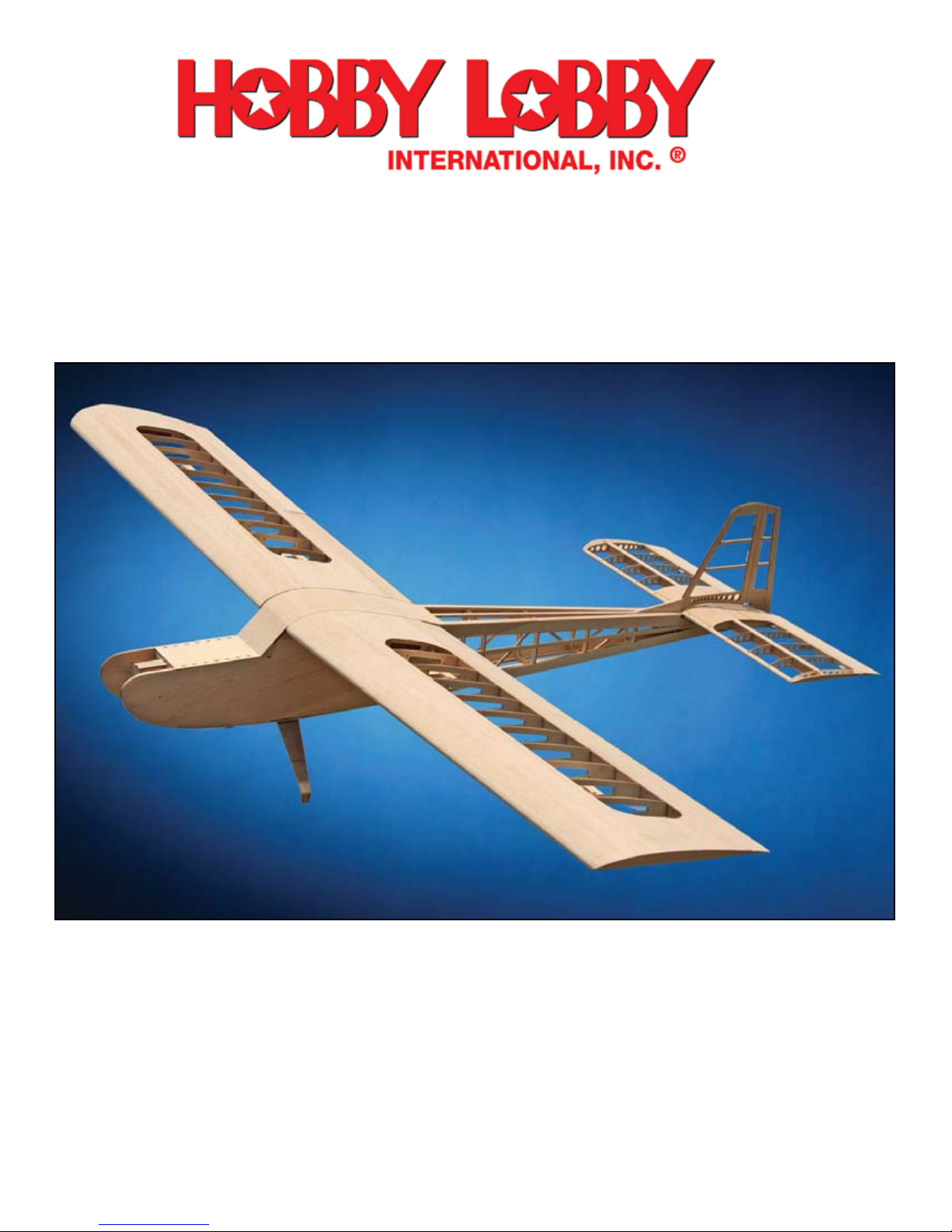
Locate the two pinning blocks supplied. Note that they have a
counter sink on one side. This is the side that the nail must be
inserted from. Place the block on a piece of scrap wood to prevent
the ber block from tearing out when the nail is driven through.
Now hammer the nail through just far enough to exit the block.
Next place the block up against the side of the bench or other
heavy object and nish installing the nail. When done, the nail
head should be in the recess so the block can sit at on the bench.
Repeat this process with the second pinning block assembly.
1
WING ASSEMBLY
During the wing assembly you will be making several subassemblies. In some cases you will be making
a left and right-handed assembly. It is best to make both assemblies at the same time in a mirror image of
each other to minimize the possibility of making two assemblies of the same hand. In the case of the rib
doublers, it is important that these be installed on the correct side of the rib. To help clarify this we will
refer to these as the Root Side and Tip Side of the part. The Root Side being the side that faces the direction
of the wing root and the Tip Side being the side that faces the wing tip. Compare each assembly to the plans
each time as they may vary. If installed on the wrong side of the rib they will not function properly.
c 1
c 2
Cut the wing plans between the left and right
panel and lay one of the plans on the workbench. Cover the plans with waxed paper. The
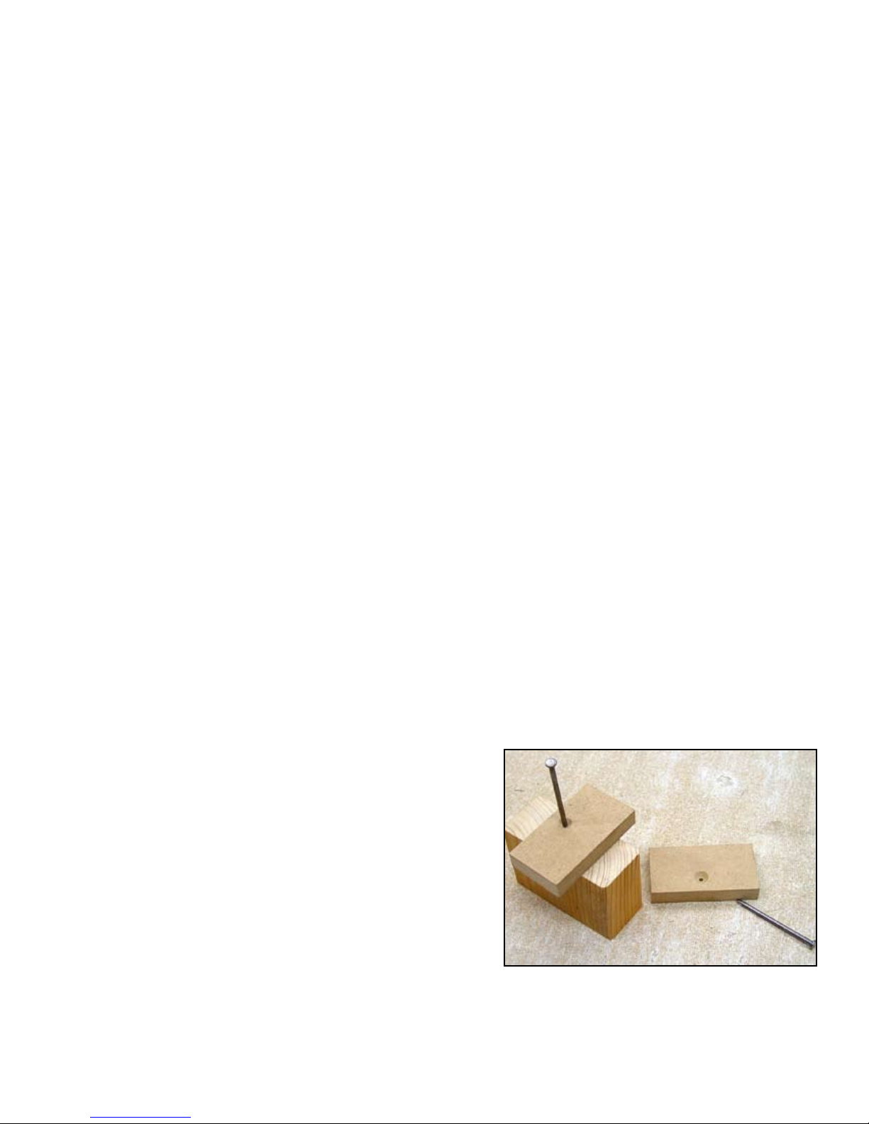
root rib assembly, W1 is composed of two
1/8” ply ribs (W1-IN and W1-OUT) that must
be assembled before installing into the wing.
This is an example of a left and right-handed
assembly. W1-IN should be facing into the
wing (Tip Side) and W1-OUT should be facing toward the fuselage (Root Side) when the
assembly is installed into the wing. Locate
W1-IN and W1-OUT and use the registration pins in the holes provided at the front and
back of the ribs to assemble them. Use plenty
of pressure to hold the assembly perfectly at
until the glue has cured. Assemble bothW1
assemblies at the same time.
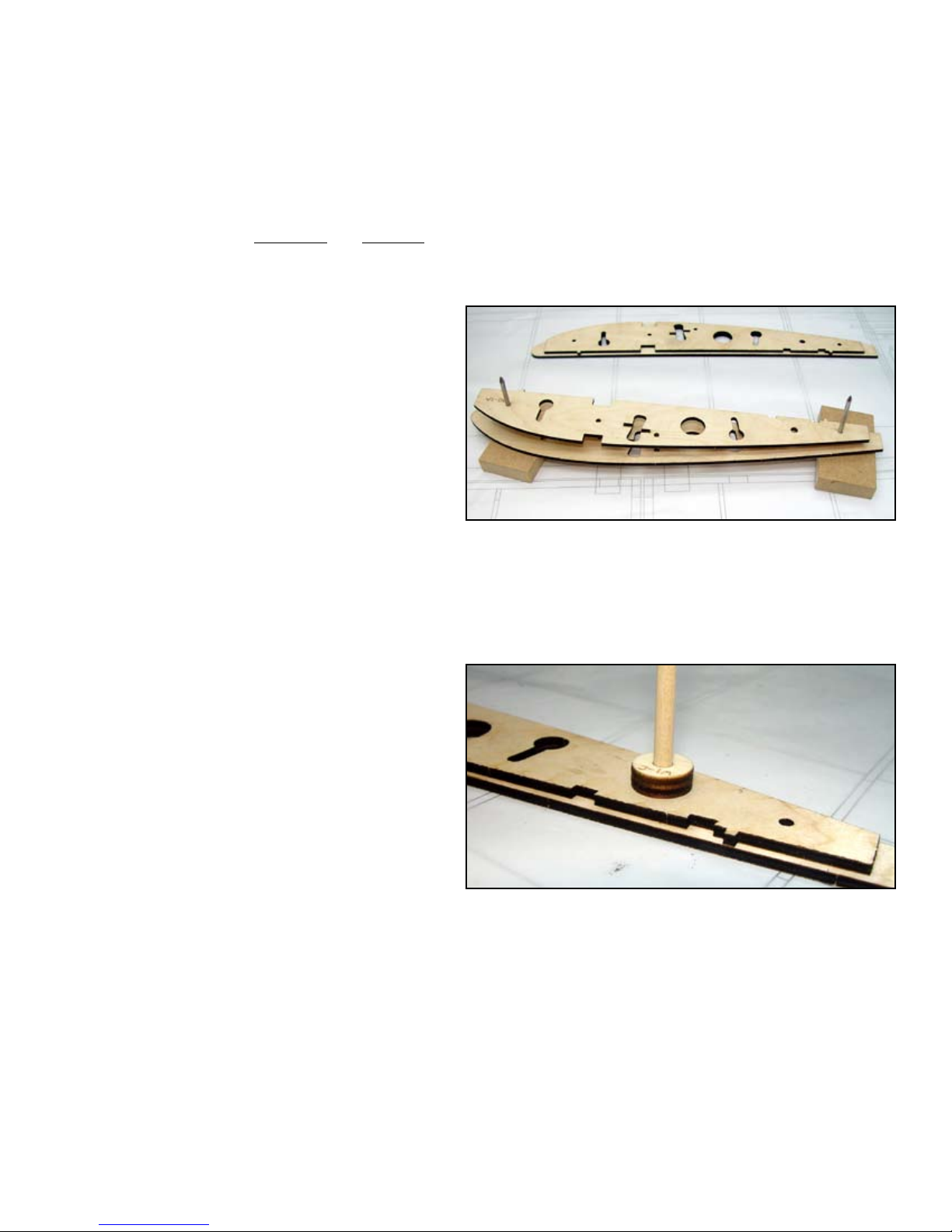
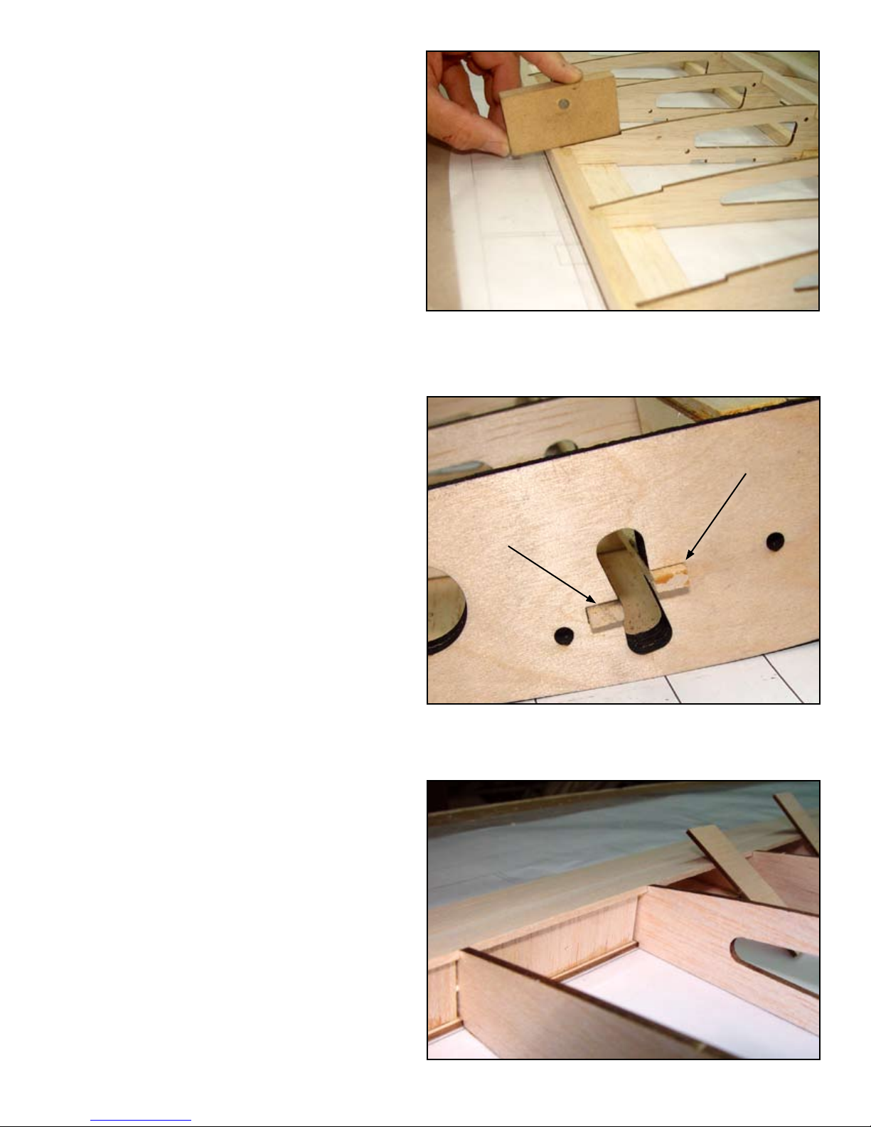
Use a 3/16” dowel as a temporary alignment
tool to align W1-C with the 3/16” hole at the
aft end of the W1 assembly and the glue W1-C
in place. W1-C should be on the Tip Side of
the W1 assembly.
The W1/W1-A assembly in the background is for the left wing. The
right wing W1 assembly is being prepared in the foreground with
W1 on the bottom and W1-A about to be glued to it on the registration pins. This pin positioning system will be used thoughout the
build.
c 3
Using the registration pins in the holes provided, glue W1-A to the W1 assembly on the
Tip Side.
2
W1-C will serve as a guide for the anti pivot pin when installed.
Here it is being positioned by the temporary use of a 3/16” dowel.
Take care not to glue the dowel into the assembly.
c 4
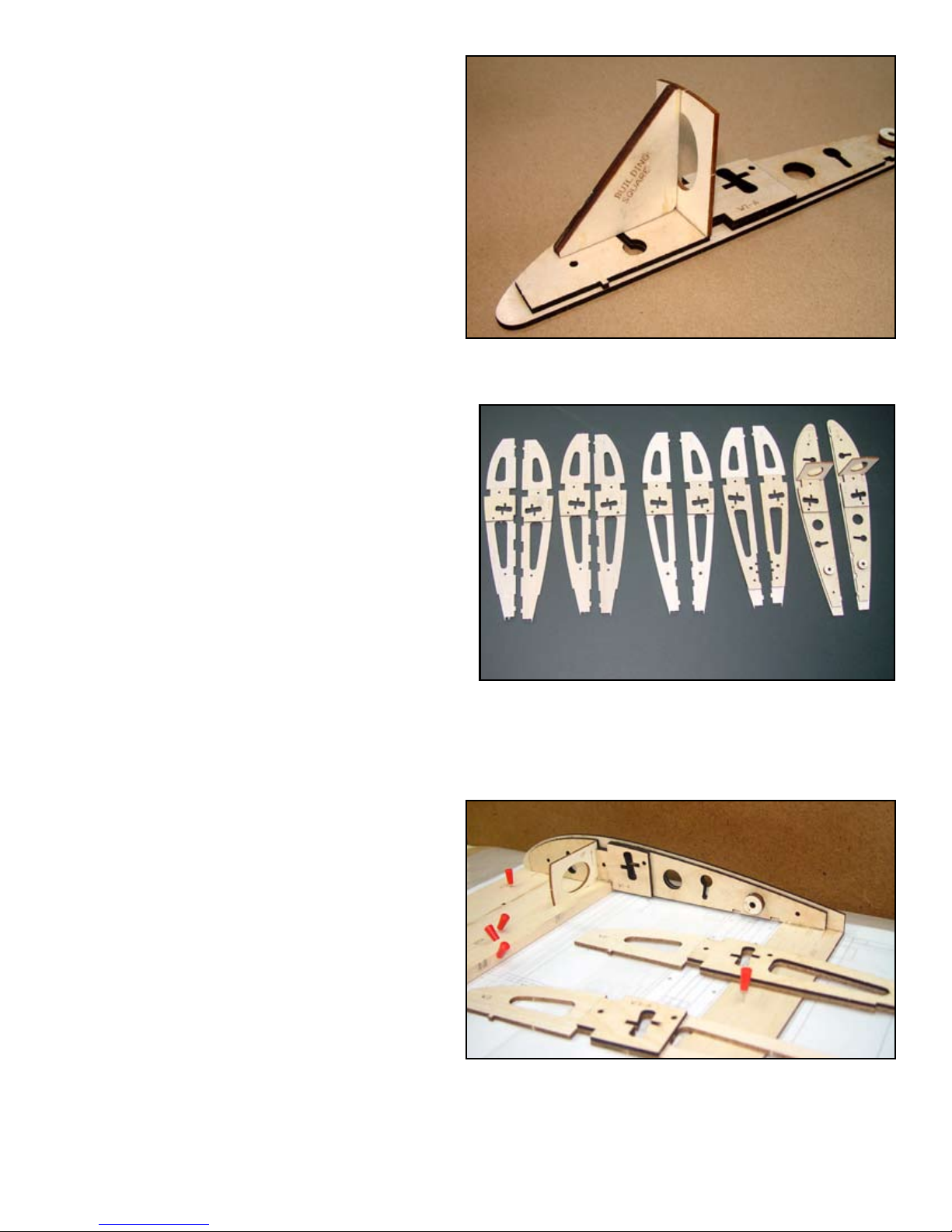
The dihedral angle will be set by W1-B so it
is important that W1-B be accurately tted in
position, Glue W1-B to the W1 assembly engaging the notch in W1-A. W1-B must be per-
fectly at against the W1 assembly. Use the
building square to insure that W1-B is at 90°
to the W1 assembly.
c 5
c 6
c 7
c 8
c 9
c 10
Again, using the registration pins in the holes
provided, glue W2-A to W2. Note that W2-A
should be on the Tip Side of W2.
Glue W3-A to the Tip Side of W3.
Glue W4-A to the Root Side of W4.
Glue W5-A to the Tip Side of W5.
Carefully align the leading edge plate (LEPA) with the plans and pin in place. You may
notice a discrepancy between the parts and
the plans as far as position is concerned. This
is normal as the paper the plans are printed
on can change size with changes in temperature and humidity. Align the slot in TEP with
the W2 on the plans and use the plans only to
align the parts. The parts are correct.
Temporarily place ribs W2 and W13 in there
respective notches in LEP, place a 3/8” x 1/2”
X 48” balsa spar in the bottom notches in each
rib to align it and then pin it at W2 and W13.
W1-B will determine the correct dihedral angle for your wing so it
must be assembled accurately. Make sure it is fully engaged in the
tab of W1-A and at against the W1 assembly.
W1W5 W4 W3 W2
The rib subassemblies should look like this. It is best to assembly
them all at the same time to avoid errors. When installing them into
the wing, observe the correct direction they face, Root Side or Tip
Side as they will vary.
c 11
Place (TEP) into position with the notches for
Ribs W2 and W13 fully engaged. Make sure
ribs W2 and W13 are perfectly parallel with
the ribs on the plans and then pin TEP and
the bottom spar in place then remove W2 and
W13.
c 12
Carefully align the bottom sheeting part A
(BSA) to LEP and glue it to LEP.
c 13
Use Epoxy to glue the W1 assembly to the
wing assembly, LEP, TEP, BSA and the bot-
tom spar. Make sure the bottom spar is fully
engaged in the notch provided in the W1 assembly and that W1-B is glued to the bottom
spar. W1-B will set the correct dihedral so it
must be at against BSA when installed.
LEP and TEP have been positioned. BSA has been installed and
now the W1 assembly is being Epoxyed to the wing assembly.
3

c 14
Loose t all ribs into there appropriate notches
in LEP, then use thin CA to glue them in and
use the Building Square to insure that each rib
is at 90° to the bench. Assure that all ribs are
bottomed in there respective notches before
applying glue. Glue them at LEP, the bottom
spar and TEP. Ribs W2 and W3 will also be
glued to BSA. NOTE: Ribs W2 through W6
must be in their correct locations or you will
not be able to insert the wing bar later. They
look very similar however the buttery opening is cut to accommodate the dihedral angle
and will not line up if out of sequence.
c 15
c 16
Trim the bottom spar ush with the outside
of W15.
Rib installation is underway, make sure each rib is in the correct
location and use the building square to insure all ribs are perpendicular to the bench.
Plane or sand a slight bevel on the bottom of the wing tip (WT)
to increase glue land. Use the 45° gusset (WTG) to get the correct
angle on it and glue it at the leading and trailing edge as well as
the gusset. Align the gusset on center with the spar. Glue in a 1”
piece of 1” triangle stock at the leading edge and a 1” piece of
¾” triangle stock at the trailing edge. Cut and glue pieces of 3/8”
triangle stoct to W14 and WT between the leading edge and the
gusset and between the gusset and the trailing edge. Use a razor
plane to plane the leading edge and trailing edge triangle stock
ller pieces to contour with W15 and WT. Use a straight edge
across the top of W14 and W15 to help align the top of WT.
RIGHT: the wing tip (WT) has been installed with WTG and the triangle stock
for and aft, all that remains is to place the
1/4” triangle stock at the bottom.
c 17
Place the top spar in position in the notches
provided and mark the location of the W1
assembly. Trim the spar off at this line then
place the spar in position and use aliphatic
resin to glue in the top spar. Weight it to assure it remains bottomed in the rib notches
until cured.
c 18
Glue on the ½” x ½” x 48” trailing edge, make
sure it is also glued to each rib.
4
Top spar and trailing edge installed, next will be the trailing edge
top sheeting being prepared at the left.
c 19
Use a razor plane to shape the trailing edge of
the ½” square into contour with the ribs. Use
a short straight edge to guide material removal. Plane the tip to contour with the ribs and
trailing edge as well. The trailing edge sheet
will extend out to the wing tip. When shaping
the tip, use a straight edge laid on top of W14
and W15 to determine when WT is correctly
shaped.
c 20
c 21
c 22
Install and glue 3/32” sheer webs to the front
of the spars, make sure that the sheer webs
are ush with the top of the ribs. Between W3
and W4 use SW-W4, this sheer web must also
be ush with the tops of the ribs. This will
provide a ledge for installing the leading edge
sheeting later.
Install and glue the ½” x ¾” x 48” leading
edge to LEP and each rib.
Cut two 12-1/2” pieces of 1/8” x ¼” basswood these will be the Wing Bar Guide Rails.
Install these into the slots provided in the
wing bar buttery opening. These will serve
to guide the wing bar when installing into the
wing. Tolerances here are very tight so make
sure each strip is bottomed it the slot before
applying glue, test t the wing bar and sand
the basswood sticks as necessary for a smooth
t, then glue in place.
Planing the trailing edge to contour with the ribs. here one of the
pinning blocks serves as a straight edge to check material removal.
The wing bar guide rails are test tted and adjusted as necessary
for a smooth t when the wing bar is inserted. Then they are glued
rmly in place.
c 23
Install and glue the trailing edge anti crush
webbing between TEP and the top sheeting.
Recess the webbing as required until it contacts both the top and bottom sheeting and
then glue it in place.
RIGHT: The trailing edge ant-crush webbing is installed between TEB and the top
trailing edge sheeting.
5
c 24
c 25
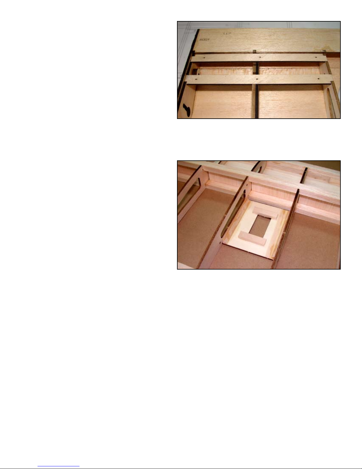
Install and glue the two anti pivot PIN hatch
screw rails (APHR) in the slots provided in
ribs W1, W2 and W3. Use the following pro-
cedure for a perfect t. Lay the screw rails
in the notches provided in W1, W2 and W3.
Lay the hatch (PPHC) over these and align
the screw holes. Install six #2 X ¼: at head
wood screws through the hatch and into the
screw rails. Apply glue to the ribs and then
place this assembly in the ribs. When the glue
has cured, remove the screws and the hatch
cover.
Assemble the bottom sheeting supplied in two
pieces, BS-A and BS-B. Glue this assembly to
the wing and then remove the dash cut material.
The anti-pivot pin hatch screw rails glue to W1, W2 and W3. Occasional access to the pivot pin assembly may be required to check
or change the rubber band.
c 26
c 27
c 29
Cut four pieces of 3/16” x 3/8” basswood
1-1/2” long and glue them to the wing servo
mount (WSM) at the front and back of the
servo opening to provide screw support. Glue
one servo mount assembly between W4 and
W5 and one between W11 and W12 in the
notches provided, the basswood blocks should
be on the inside.
Cut four pieces of ¼” triangle stock 3-1/2”
long and glue them in the corners between the
servo mounts and the ribs for additional bracing.
The leading edge sheeting is supplied as twp
4” and one 3” 3/32” x 48” sheets. These must
be edge glued and then two 4-1/4” sheets cut
from this assembly. Butt the straight edge of
this sheet up against the top spar and use a
piece of masking tape at each rib to hold it
rmly against the spar. Using the tape as a
hinge, swing the sheet back and apply a bead
of aliphatic resin glue to the top spar and then
bring the sheeting back down in to position.
Let this glue cure before proceeding.
The servo mount is glued to the ribs and then braced with 1/4”
triangle stock. The basswood blocks are added for screw support.
6

The leading edge is checked with a straight edge for contour to the
ribs in preparation for installing the leading edge sheeting.
The leading edge is shaped to contour with all ribs and W1-IN in
preparation for installing the top leading edge sheeting.
c 29
Apply a bead of aliphatic resin glue to the
leading edge of ribs W1 and W2 under the
sheeting and along the entire leading edge.
Use four inch pieces of masking tape at each
rib to pull the leading edge sheeting tightly
down against the ribs and the leading edge.
Turn the wing over and apply thin CA to
each rib to complete the leading edge sheeting installation. Trim and sand as necessary.
The leading edge sheeting is rst glued to the top spar and held
rmly in place with strips of masking tape until cured.
7
c 30
Temporarily install the pivot pin hatch cover
(PPHC) with some #2 screws.
c 31
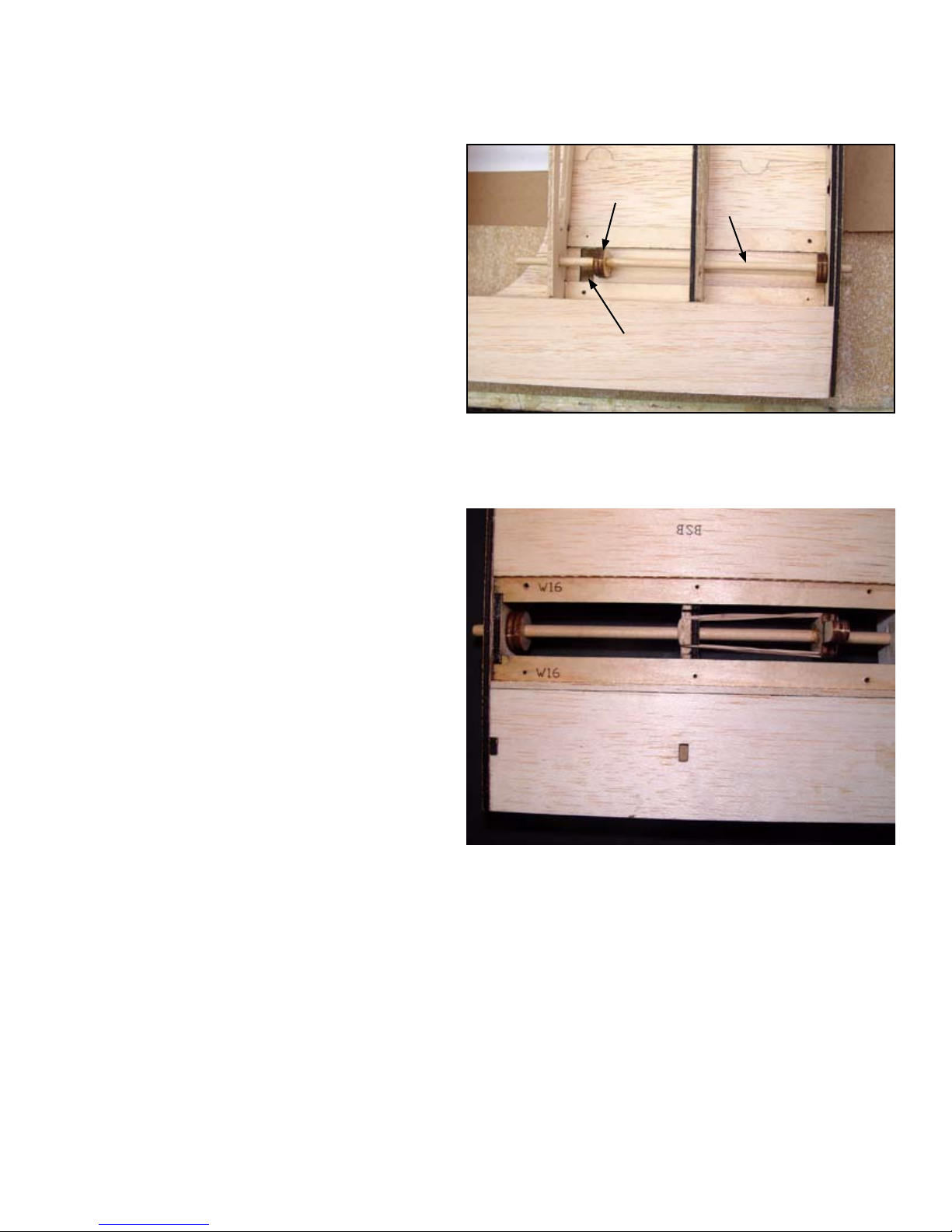
Before installing the top center section sheeting we will need to install and test the wing
pivot pin assembly. The pivot pin must move
freely in the 3/16” holes provided in ribs
W1, W2 and W3. Sand the 3/16” x 7” dowel
smooth and slightly round one end. This end
will snap into the hole in the fuselage wing
platform when installing the wing onto the
fuselage. The dowel should t loose enough
that if the wing were tipped up the dowel
would fall out. Slide the dowel through W1
and W2 and then through APL and then on
through W3. APL should protrude through the
T shaped opening in PPHC. Place the dowel
so 5/16” of it protrudes out of W1. With the
dowel in this position, slide ALP so it bottoms
in the narrow end of the T shaped slot. Glue
APL to the dowel in this position.
APL
ANTIPIVOT
PIN
T SLOT
The anti pivot pin is checked for t and adjusted for throw before
APL is glued permanently in place. The pin must slide freely in the
holes in W1, W2 and W3.
c 32
c 33
c 34
Flip the wing over and remove PPHC. Install
a #27, 1/8” rubber band around the slots provided in W2 and the notches provided in APL
and then reinstall PPHC. Test the pin by sliding it back and rotating it in the T shaped slot
to retain it in the retracted position. When you
rotate it to the center of the T shaped opening it should snap into the extended position.
NOTE: Rubber bands age and can become
brittle and weak; it is recommended that you
change these rubber bands once a year to insure proper performance.
A #8 rubber band provides the tension to retain the anti-pivot pin in
the correct position.
The top center section sheeting is supplied in two sections, TRS-B and TRS-C Glue one to the aft edge of
the spar and one to the front of the trailing edge sheeting. Trim as necessary where they meet for a good
t.
At the wing tip, glue a short piece of the scrap cut off of the spars to the end of the top spar and the aft edge
of the leading edge sheeting to ll the gap between the leading edge sheeting and the wing tip sheeting.
c 35
The top wing tip sheeting is supplied in two sections, TWTS-A and TWTS-B. Glue TWTS-B to the trailing
edge of the top spar, the tip (TS) and W14 and W15. Glue the TWTS-B sheet to the trailing edge and trim
to t where they meet.
8
 Loading...