

Page 1

1
Instruction Manual
Telemaster Electro V2 ARF
Wingspan: 73-1/4 in.
Length: 53-1/2 in.
Wing Area: 848 sq. in.
Weight (with battery): 88 oz.
Page 2
2
Before starting, use the
Contents List to take an
inventory and make sure it is
complete. If any parts are
missing or are not of
acceptable quality, contact
Hobby-Lobby.com Support
at 866-512-1444.
This manual assumes the
builder possess intermediate
assembly skills. Seek help
from another pilot or an
experienced modeler if you
are unsure how to complete any step in this manual.
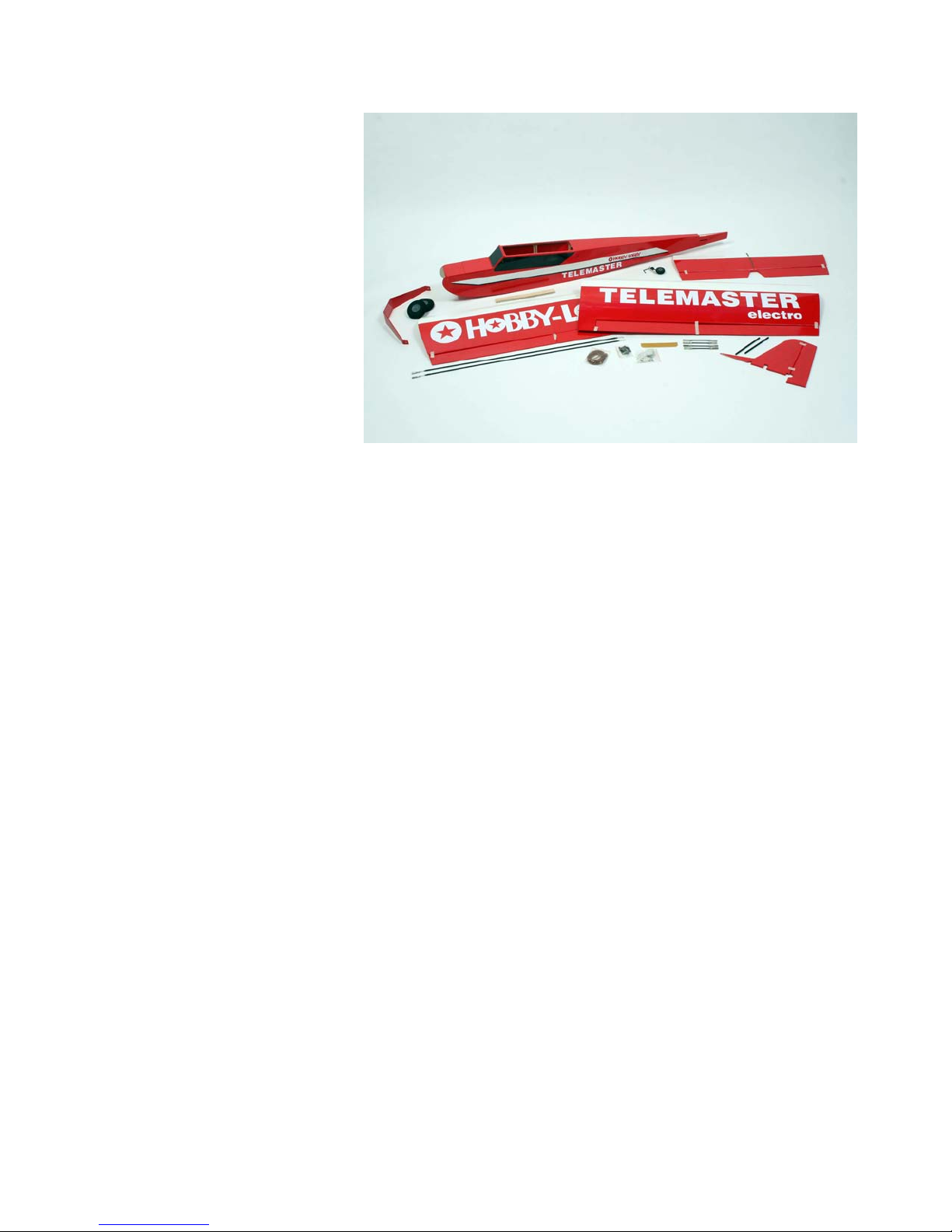
Contents List
! Fuselage
! 2 Wing Panels
! Horizontal Stabilizer and Elevator
! Vertical Stabilizer and Rudder
! Wooden Wing Joiner
! Aluminum Landing Gear
! Main Wheels and Steerable Tail Wheel
! Pushrods, Control Horns, Pin Hinges and assorted fasteners
Additional Items Required
! 6-channel Aircraft Radio w/ Receiver (minimum)
! 4000mah, 4-cell, 14.8v Lipo battery
! (6) Standard sized servos
! (2) 12” Servo extensions
! (4) 6” Servo extensions
! 50-60 amp Brushless ESC
! AXI 2826/12 Brushless Motor and radial mount set
! APC 12x6 “E” Propeller
! Glues, solder, connectors
Page 3
3
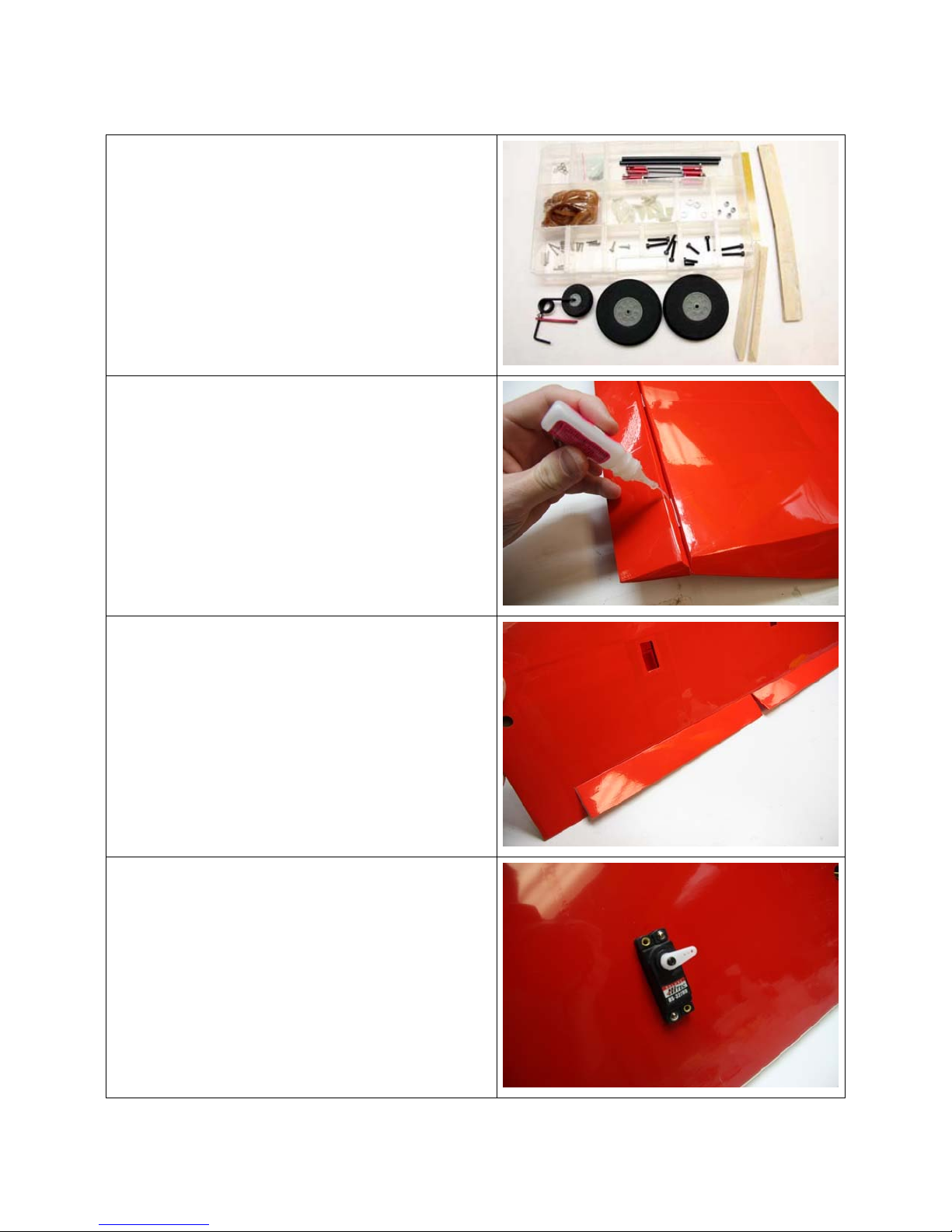
1. After unpacking all parts, sort the
hardware and place like parts into
separate holders. This will speed the
building process and give you a good
visual of all the hardware provided.
2. Begin by hinging the ailerons to the main
wing panels using the CA hinges. Insert
the hinges fully then flex and apply thin
CA glue to the hinges from the top and
bottom allowing the glue to wick into the
wood. There should only be a small gap
between the ailerons and the wing.
3. Once the hinges are set, flex the ailerons
a few times to break-in the hinge.
4. Now install the flaps in the same manner
as you did the ailerons.
5. After all wing control surfaces are hinged,
check for free movement and prepare to
install the servos.
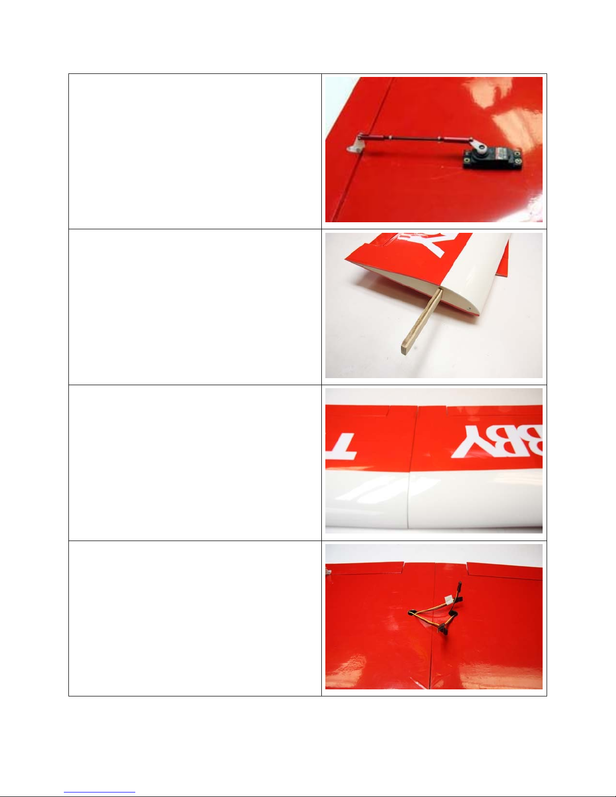
6. Add 12” servo extensions to the aileron
servos and insert the servos in the wing
with the output arm facing the trailing
edge of the wing and screw in place.
Page 4
4
7. Install the flap servos in the same manor.
The output arms on the two flap servos
should face the same direction. The
servo control horns for both flap servos
should also face the same way. That will
allow them to operate together when tied
into the flap channel on the receiver.
Install the control horns and linkages to
the flaps and the ailerons.
8. Mix up some 30-minute epoxy and apply
to the ends of the wings and in the slots
for the wooden wing joiner.
9. Slide the wings together and make sure
they are aligned. Use rubbing alcohol
and a paper towel to wipe off any excess
glue that squeezes out.
10. The servo wires should exit the holes on
the bottom of the wing as shown.
Page 5

5
11. Locate the fiberglass plate and place on
top of the wing at the trailing edge. Trace
the outline and remove the covering
below the traced line. Glue the fiberglass
plate to the wing with medium or thick CA
glue.
12. Locate the horizontal stabilizer with
elevator. Install the elevator to the
stabilizer with the CA hinges using thin
CA glue. There should be a very small
gap between the stabilizer and the
elevator.
13. Trail fit the stabilizer to the fuselage. Use
a marker and trace the area around the
fuselage.
14. Use a hobby knife and carefully cut the
covering away just inside the traced lines.
Note: Use a sharp blade and only use
enough force to cut the covering. Do not
cut down into the wood.
Page 6

6
15. Mix up some epoxy and glue the
horizontal stabilizer to the fuselage.
Make sure it is centered and parallel to
the horizon.
16. Locate the two balsa wood triangle stock
pieces. These will be used to strengthen
the stabilizer. Hold them in place as
shown and trace around the edges.
Remove the covering and glue them in
place on both sides of the fuselage using
CA glue or epoxy.
17. With the fuselage right side up, trail fit the
vertical stabilizer. Trace the area on the
vertical stabilizer, remove the covering,
and use epoxy or CA glue to install it.
Make sure to wipe off any excess glue.
18. Locate the tail wheel and prepare to
install it into the rudder.
Page 7

7
19. Use 5-minute epoxy to glue the tail wheel
wire into the slot in the rudder.
20. Install the rudder onto the vertical
stabilizer using the CA hinges and thin
CA glue.
21. Use the two larger wood screws to install
the tail wheel plate to the bottom of the
fuselage.
22. Install the rudder and elevator control
horns as shown.
Page 8

8
23. Locate the main landing gear, wheels, 4
locknuts, 4 washers, 4 mounting bolts,
and the 2 long bolts that will be used as
axles.
24. Start by installing a washer on the axle
bolt, then the wheel, then another
washer, and finally a locknut. Tighten the
nut, but not too much. The wheel should
spin freely.
25. Slide the remaining axle through the
outside of the landing gear hole and
secure with the remaining locknut.
26. Install the main landing gear to the
fuselage with the 4 mounting bolts. Note:
the landing gear has a straight edge and
a tapered edge. The tapered edge faces
the rear.
Page 9

9
27. Slide the two pushrods through the
fuselage from the front. You will need to
remove the clevis from the threaded wire
and insert that end first.
28. Make sure the pushrods go through the
proper holes. You can twist and flex the
rods as required. Once they get through
the first two holes it slides easier through
the rest. Note: The pushrods will cross
paths and exit on opposite sides at the
rear of the fuselage.
29. Reinstall the clevis on both pushrods and
connect to the rudder and elevator
control horns. Note: The clevis can be
used for mechanical adjustment to center
the control surface.
30. Install the elevator and rudder servos as
shown. The out put arm should face the
rear. Connect the servo arms onto the
pushrod z-bends before installing on the
servos.
Page 10

10
31. Insert the two carbon fiber rods into the
slots on the fuselage and secure with thin
CA glue.
32. The receiver can be mounted using
Velcro, double-sided tape, or a zip tie.
Use 6” servo extension leads for the flap
and aileron servo channels to make
connecting them easier when installing
the wing. Use the included rubber bands
to install the wing on the fuselage.
33. Install the radial mount plate to your
motor and use 4 bolts to mount the motor
to the firewall. Install your prop and
secure with a washer and nut.
34. The ESC can be installed in the
fuselage next to the battery area or
along side the motor mount. Use Velcro
or double-sided tape to secure it.
Page 11

11
35. The battery is inserted through the front
hatch and is secured using the supplied
Velcro straps. Slide the battery forward or
aft to achieve the proper CG, which is
listed below.
36. Install the magnetic hatch by putting the
back end in first and then laying the front
down. Remove the hatch by first lifting
the front and pulling up and away.
37. Congratulations, you’ve finished the
assembly. Follow the information listed
below for recommended control throws
and center of gravity.
CG Location
Forward position for CG is 3-3/4” back from the Leading Edge of wing.
Aft position for CG is 4-1/2” back from the Leading Edge of wing.
Control Throws
Ailerons = 10mm Up and Down for Low Rates
20mm Up and Down High Rates
Flaps = As much as you want!
Elevator = 10mm Up and Down for Low Rates
15mm Up and Down for High Rates
Rudder = 10mm Left and Right for Low Rates
20mm Left and Right for High Rates
Page 12

12
Preflight
If you are new to flying R/C aircraft we recommend you have a fellow R/C modeler help
you with the first flight. Some items you will need to complete on your first preflight are:
1. Aircraft assembled correctly and ready for flight.
2. All control throws set per this manual.
3. Transmitter fully charged and on the correct model.
4. Aircraft balances at the recommended location.
5. Flight batteries are fully charged and secure.
6. All electronics are operating correctly, in the proper direction, and secure.
7. Complete a radio range check per your radio’s manual.
8. Balance propeller and make sure it is secure.
9. Wait for a calm or light wind day for first flights.
Flying
You will soon find out the Telemaster Electro is a real pleasure to fly. Takeoffs,
landings, and flaps down slow flight are all easy to accomplish. Even if you have never
flown a tail wheel airplane before, the Telemaster Electro is an easy transition.
We hope you enjoy your Telemaster as much as we do!
Happy Landings!
WARNING – THIS IS NOT A TOY!
Radio controlled model aircraft are capable of inflicting serious injury and/or property damage if not assembled, operated, and
maintained in a competent and safe manner. If you are not already experienced with radio-controlled models, we strongly suggest
that you find an experienced modeler to assist you.
Warranty
Hobby-Lobby guarantees this kit to be free from defects in both material and workmanship at the date of purchase. This warranty
does not cover any component parts damaged by use or modification. In no event shall Hobby-Lobby’s liability exceed the original
cost of the purchased kit.
Completely read through this manual before starting construction.
Page 13

13
Hobby Lobby International, Inc.
5614 Franklin Pike Circle
Brentwood, TN 37027
(1-866-512-1444)
www.hobby-lobby.com
 Loading...