

Page 1

Telemaster 40 Deluxe
Assembly Manual
Hobby Lobby International
5614 Franklin Pike Circle
Brentwood TN 37027 USA
Phone 866-512-1444
MADE IN THE USA
Page 2

Page 3

Terminology used in this manual.
With the precision of laser cut parts and notch and tab construction, the assembly and gluing sequence
becomes very important. If components are glued in place to soon, they will not allow enough movement to install other components. When instructed to install a part, do only that. You will be instructed
to glue it when it is no longer required to be moveable.
Test Fit:
Test t and install but do not glue.
Install and glue:
Permanently install the part.
Locate and prepare:
Find the parts requested, you can locate them faster using the parts locator pages at the back of this
manual. The parts locator will direct you to the correct sheet number as well as describe the part for
easier identication. Most of the parts are supplied still in the sheet. These sheets are called the carrier
sheet and the parts are held in the carrier sheet by small breaks in the cutting line. These are called
retainer breaks and in most cases the parts can be extricated by simply exing the carrier sheet and the
retainer breaks will release the parts. In harder materials it may be necessary to use your hobby knife to
sever the retainer breaks to remove the parts. After removing the parts, a small nub may remain where
the retainer break was, this must be removed with a light swipe of sandpaper so it will not interfere with
the parts t.
Adhesives:
There are four primary types of adhesives recommended for constructing your model. They are CyanoAcrilate (referred to as CA) in all viscosities, Aliphatic Resin Glue (carpenters glue), Polyurethane glue
referred to as PU and Epoxy. CA is the primary adhesive to use however there are times when it is not
the best choice.
They are:
1. When you need more time to carefully position a part than a fast setting adhesive will allow.
2. When attaching plastic such as a windshield (Use Pacer formula 560 here).
3. When gluing laser cut aircraft grade plywood’s. The microwave set adhesives used in aircraft grade
plywood does not ablate well under a laser beam. As a result it burns the wood bers near by leaving
a charred edge. Fast setting CA adhesives do not allow time for the adhesive to penetrate this layer of
char and bond to the wood ber underneath. Use a slower setting adhesive such as Aliphatic Resin for
maximum strength use Epoxy on aircraft grade ply parts. Lite Ply’s do not use this type of adhesive and
do not suffer from this problem.
To apply thin CA we recommend the Dave Brown pipets available from Hobby Lobby. Be sure to stretch
the end (pull it with a pair of pliers) to a thin applicator tip, as they are not supplied in this conguration.
1
Page 4

Your Telemaster kit can be constructed with several options. You can build it as a standard gear (tail
dragger), the classic Telemaster stance or a more modern tricycle gear model. You can also build
either of these to accommodate the Telemaster Float kit for operation off of water. As you progress
through the assembly procedures we will point out the various deviations from the basic standard
gear conguration.
Assembling the registration pins.
We will be using two types of pins; registration pins and push pins. Registration
pins are assembled from two ber blocks
and two specially prepared 2-1/2” nails.
Push pins will be used to temporarily secure parts to the building board.
Locate the two pinning blocks supplied.
Note that they have a counter sink on one
side. This is the side that the nail must be
inserted from. Place the block on a piece
of scrap wood to prevent the ber block
from tearing out when the nail is driven
through. Now hammer the nail through
just far enough to exit the block. Next
place the block up against the side of the
bench or other heavy object and nish installing the nail. When done, the nail head
should be in the recess so the block can
sit at on the bench. Repeat this process
with the second pinning block assembly.
FUSELAGE ASSEMBLY
c 1
c 2
Locate the rewall sections, FW-A and
FW-B. Place FW-B on the registration
pins. Test t FW-A; make sure you have
the correct orientation so the holes line
up. Apply thick CA to FW-B and then install FW-A with the labeled side up.
Install four #6-32 blind nuts in the holes
provided from the FW-B side.
NOTE: The bolt pattern on the rewall will
t the Hobby Lobby 40 size glow motor
mount Cat #MT11022 as well as the elec-
tric motor mount supplied.
Assembly of the rewall is underway. FW-B has been installed
on the pins and now glue will be applied to the top of FW-B and
then FW-A will be installed on the pins and pressed into contact
with FW-B.
2
Page 5
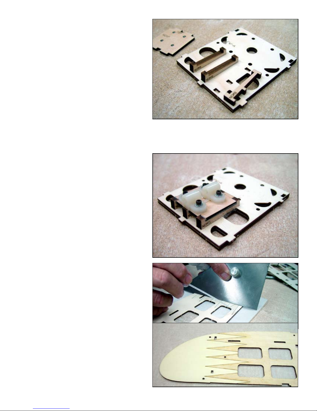
c 3
TRIKE VERSION ONLY
A. Locate NGNP and install four #4-40
blind nuts.
B. Install and glue three NGMB into FW-A
in the slots provided. Use Epoxy or PU
glue for this.
C. Install and glue NGNP to the three
NGMB parts, the blind nuts should be on
the side facing FW-A.
ABOVE: Three nose gear mounting brackets (NGMB) are being installed into the rewall assembly. BELOW: The nose gear
nut plate NGNP has been installed onto the three nose gear
mounting brackets and the nylon nose gear bearing has been
installed.
c 4
The fuselage sides are supplied in two
sections, FS-A and FS-B, they are joined
by a nger joint at the front. Place the
parts over a piece of parchment paper
and apply thin CA. Wipe off any excess
glue and sand out any bumps.
ABOVE: A straight edge is being used to force
the two fuselage sections at against the building
board while thin CA is being applied.
BELOW: The nished nger joint.
3
Page 6
c 5
We will now start the fuselage side subassemblies; make sure you make a left
and a right side. Place one of the fuselage sides on the registration pins using
holes A and D. Slide FD down the pins to
test t. When satised with the t, remove
FD and apply thick CA to the back (the
side facing the FS assembly) and then
reinstall it onto the pins and slide it into
contact with the FS assembly. Apply even
pressure until the CA has cured. Repeat
this process for the remaining side and
remember to make it a mirror image of the
side you just created.
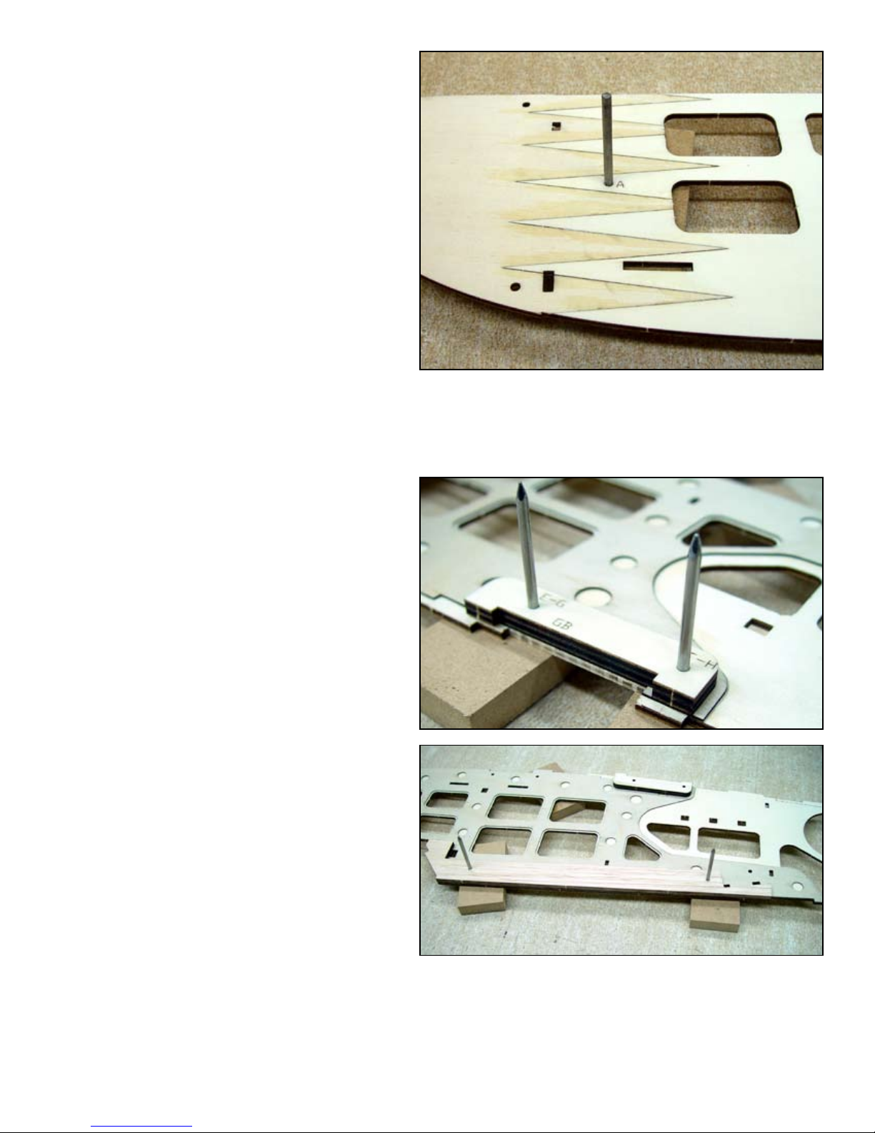
c 6
c 7
c 8
If you are building the trike version, remove the dash cut material by register pin
holes G and H.
Next we will install the mains landing gear
brace (GB). If your are building the standard gear version (tail dragger) install the
register pins in holes E and F and install
GB. If you building the trike version, install the register pins in holes G and H
and install GB
Place the register pins in holes B and C
and install and glue the fuselage wing
saddle (FWS).
ABOVE: The right fuselage side with a registration pin inserted
in holes A and D ready to install the doubler FD.
BELOW: With the registration pins inserted in holes G and H,
the gear brace for the trike version is being installed.
4
Page 7
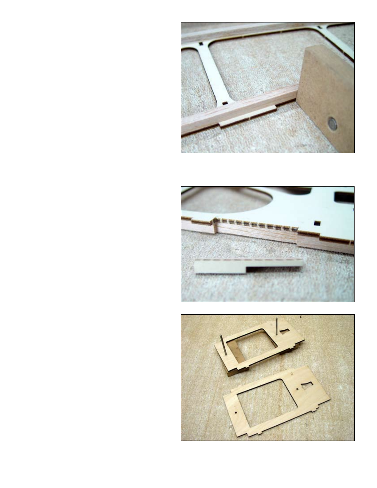
c 9
Locate four ¼” x ¼” x 36” sticks, they will
be glued into each corner of the fuselage
aft section. Start with one stick butted up
against FD. Note that the stick must be
glued in line with the inner notches. This
stick will terminate at and to include F9.
c 10
c 11
Install the top corner stringer starting at
the back of FWS and terminating at and
to include F9.
ABOVE: The 1/4” square corner stringers are being installed.
One of the pinning blocks is being used to align the stringer
with the edge of the fuselage side.
If you plan to use oats you will need to
install the oat hard point. Remove the
dash cut material just behind F4, includ-
ing a notch in the ¼” square stringer.
c 12
Assemble F2 from two 1/8” ply sections
using the register pins.
ABOVE: F2 is being assembled on the registration pins, thick
CA is used to laminate the two parts.
5
Page 8
c 13
Install two 1/4” x 20 blind nuts into
FWBP.
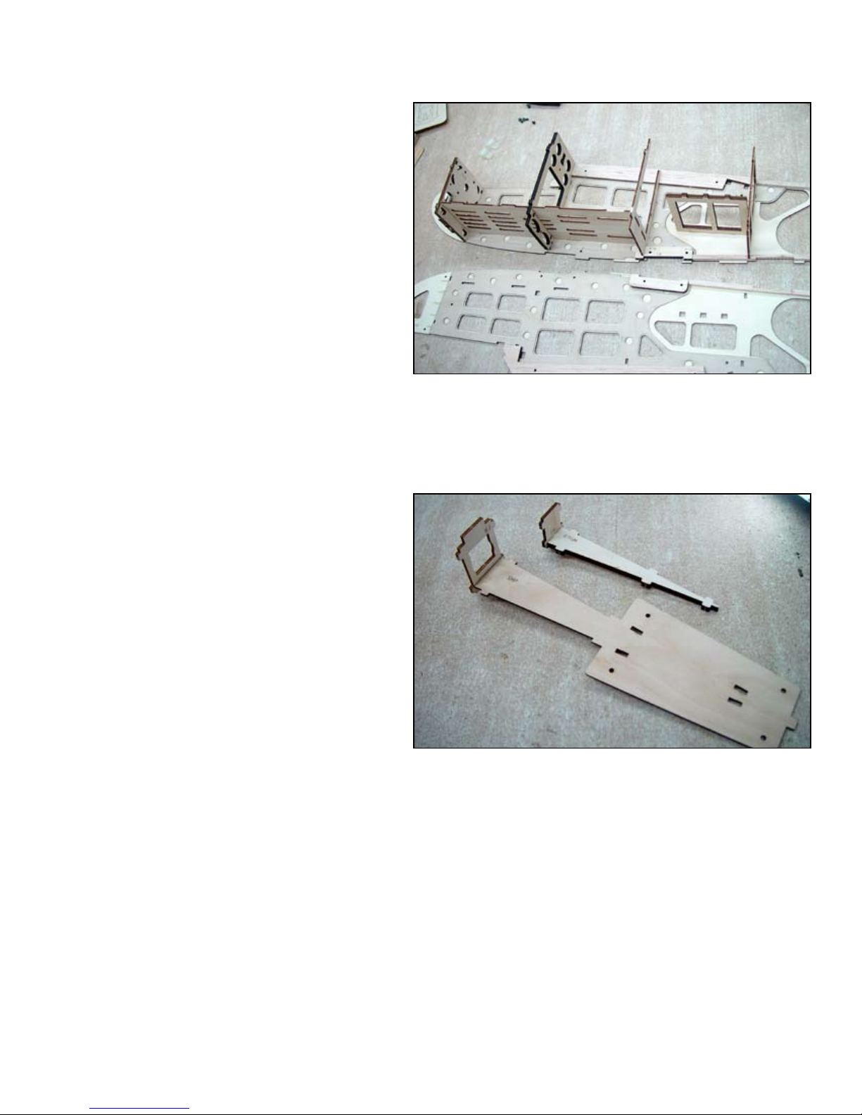
c 14
c 15
The rst glue up of the fuselage will consist of the rewall assembly FW-A&B, the
fuselage oor FF, the F2 assembly, F3,
F4, the wing bolt plate FWBP, the hatch
mounting plate FHMP and the servo tray
FST. Use a slow curing adhesive such
as aliphatic resin to allow time to work.
Glue each part and install it into the right
side. Next apply glue to the left side of all
these components and install the left side.
Place a at board or other object on this
assembly until it has cured. Make sure all
tabs are bottomed in the notches and all
components t ush to both sides.
ABOVE: Joining the fuselage side assemblies begins by installing formers, the fuselage oor, wing bolt plate and the forward
hatch mounting plate in one side and then applying glue to the
top side of these components and installing the remaining fuselage side. In the photo, the wing bolt plate and the forward hatch
mounting plate remain to be installed.
Before pulling the tail section together we
need to pre-assemble F9 with FTGM and
F8 with SMP. Use your square to assure
that these components are at 90º to each
other.
c 16
Install the F8 and F9 assemblies at the
same time. Apply glue to both sides of
these assemblies and install. Pulling the
tail section together. It is very important
that these parts be completely inserted
into their respective notches to assure the
stabilizer mount will be level. Use clamps,
tape or rubber bands to assure these
parts t tightly.
ABOVE: The fuselage tail gear mount (FTGM) has been joined
with F9 and the stabilizer mounting plate (SMP) has been
joined with F8
6
Page 9
c 17
Install and glue F5, F6 and F7. Install
each former into the notches on one side
and then tip into the other side.
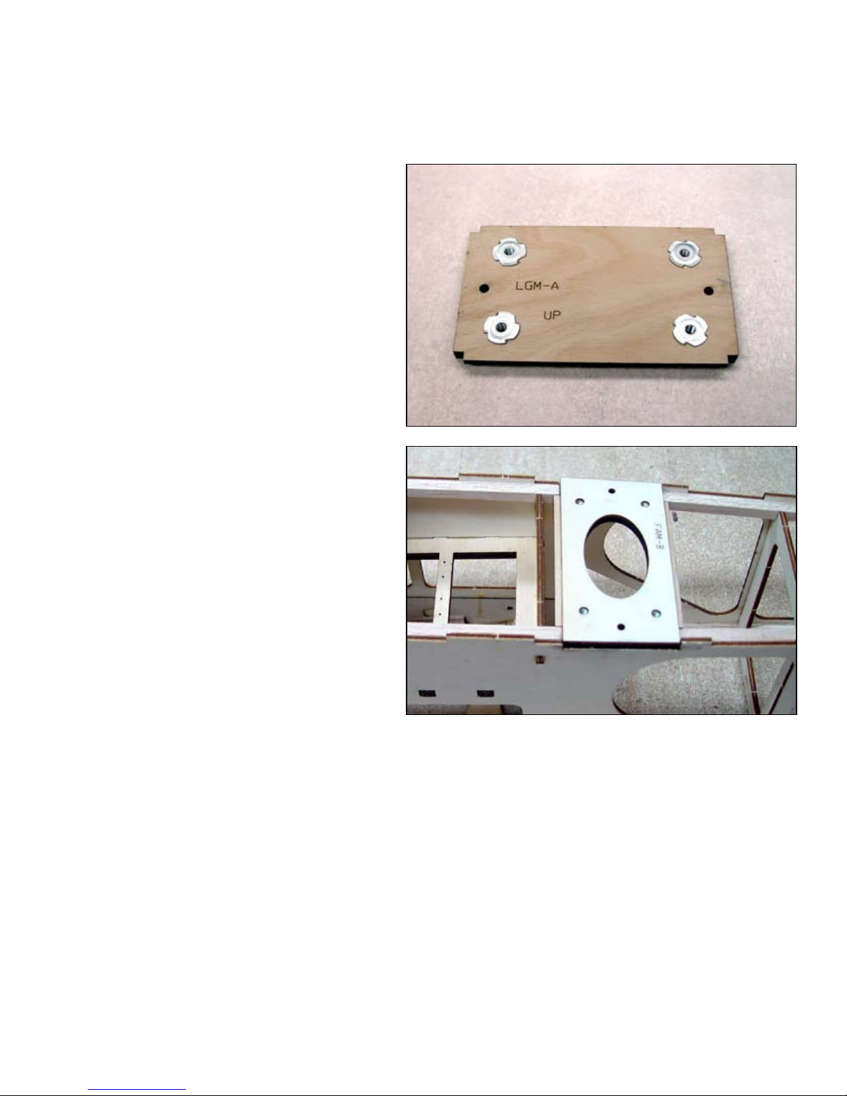
BELOW: The landing gear assembly is ready to be installed
into the fuselage. The word UP refers to its position in the fuselage, the nuts must be facing the inside of the fuselage.
c 18
c 19
Using the registration pins, assemble
the landing gear mount from LGM-A and
LGM-B. Install four #6-32 blind nuts from
the LGM-A side and install and glue it into
the fuselage side at GB. Remember this
can be positioned at one of two locations,
forward for standard gear and aft for trike
gear.
If you have opted to install the oat hard
point, now is the time to install it. Assem-
ble FAM-A and FAM-B using the register
pins. Install four #6-32 blind nuts from the
FAM-A side. Install and glue it at the location indicated just aft of F4.
c 20
Install one ¼”magnet into the hole in
FHMP, this will be part of the hatch hold
down system. Make the magnet ush
with the top of FHMP so the hatch can
t tightly.
7
Page 10

c 21
Place the remaining magnet near the one
installed in FHMP and let them join. Mark
the top of the top magnet with a magic
marker. Locate the hatch components
FHA and two FHA-H. Place the FHA on
the bench with the labeled side down and
install the remaining magnet in the hole
provided with the side you just marked
facing down. With the labeled side still
facing down, install the two FHA-H rail
hooks.
c 22
c 23
Install and glue the 4” length of 3/8” triangle stock in the notch provided at the
base of the windshield. The wide side of
the triangle stock will be perpendicular to
FHMP.
ABOVE: 3/8” Triangle stock installed.
Below: Windshield (WS) has been added.
Install and glue WS, note that a small
chamfer must be planed into it at the top
where it contacts F2.
8
Page 11

c 24
c 25
Place the hatch cover assembly onto the
fuselage and install and glue the ¾” x 4”
triangle stock onto the hatch cover. This
should butt snugly up against the 3/8” triangle stock installed in step 21.
Install and glue the top turtle deck FTD.
Use clamps or masking tape to pull the
sides snugly against FTD. Start at the tail
section and work forward.
BELOW: Clamps and tape secure the sides tightly to the top as
the adhesive cures, use this same method when installing the
fuselage bottom.
c 26
c 27
c 28
If you are building the trike version, install
LG-PLUG assembly in the notch where
the main gear would have gone. This assembly consists of LG-PLUG-A and LGPLUG-B and assembles just like the LG
assembly did.
Next we will install the fuselage bottom
FB. Note the two dash cut sections in
FB, if your building the standard version
both of these will remain intact. If you
are building the trike version, the forward
most dash cut area must be removed to
accommodate the gear mounting assem-
bly LGM-B. If you are using the oat hard
point you will need to remove the aft most
dash cut area.
Install and glue one FA to the forward bottom fuselage section just behind the rewall on each side.
ABOVE: Mount for the trike mains on the left and on the right
for the optional oat kit.
BELOW: The forward bottom sheeting BS-A and BS-B has
been installed.
c 29
Assemble the forward bottom sheeting
BS-A and BS-B and glue it into position
between the rewall and LGM.
9
Page 12

c 30
Install and glue the nose ller pieces NF.
c 31
c 32
If you are building the trike version, now is
a good time to install and adjust the nose
gear steering cable. Note that a ball link is
used on the steering tiller arm.
Locate and prepare the ve electric motor mount parts, MMA, MMB, MMH, MMV
and MMBP. Use Epoxy to or PU to as-
semble these components. Note that the
bolt pattern on the motor mount bolt plate
(MMBP) is the same as that used on the
Hobby Lobby 40 sized glow motor mount
catalog # MT11022. Use the pinning
system to assemble the laminated parts
MMA and MMB. Install MMH and MMV in
the bolt plate MMBP. Next glue the MMA/
MMB assembly to MMH and MMV.
c 33
Install the motor mount with four #6-32 X
3/8” socket head bolts and at washers.
This concludes the basic fuselage assembly. You will want to install all radio gear and control
linkages before covering the model. Once covered you will not have access to some parts of the
model.
10
Page 13

STABILIZER ASSEMBLY
c 1
c 2
c 3
Cover the stabilizer plans with parchment
or waxed paper. Prepare the stabilizer
plate (SP). Install four #4-40 blind nuts
into the holes provided. They should be
installed from the top. Pin this part in place
over the plans. Place the pins through the
blind nuts to keep them out of the way.
Iinstall the stabilizer false leading edge
(SFLE). Position the tab on SP into the
notch in SFLE and glue.
Install the stabilizer 1/8” X 1/2” basswood
bottom spar. Place into the notches provided on either side of SP and glue it in
place. Align the outer ends of tn
he spar with the plans and pin in place
with push pins.
c 4
c 5
c 6
c 7
c 8
c 9
Install and glue the false trailing edge
(SFTE) to the aft edge of SP. The center
notch will position it correctly.
install and glue two S1 ribs in the notches
provided.
install but do not glue two stabilizer sheer
webs (SSW). These will remain loose until all the ribs have been installed.
install but do not glue all remaining stabi-
lizer ribs, S2 through S6.
Before gluing the assembly this far, make
sure the bottom spars are aligned with
the plans. Begin by gluing each rib and
sheer web to the bottom spar. Make sure
each rib is bottomed in the sheer web
slot. Then glue the false leading and false
trailing edges to each rib.
install the stabilizer tips (SWT). They
should butt against S6 and against FLE,
FTE and SW. Glue these into position.
11
Page 14

c 10
Install the top spar from 1/8” X 1/2”
basswood stock. Taper the ends to butt
t to the stabilizer tips SWT. When your
satised with the t of this bevel, glue the
top spar into position.
c 11
c 12
Note that at the center of the false trailing edge and false leading edge there is
a low spot. This is to accommodate the
center section sheeting. Before installing
it you will need to sand the top of the false
trailing edge and the false leading ush to
and at the same angle as the ribs.
Install and glue the center section top
sheeting sections SCS-A and SCS-F. After the glue has cured, remove the dash
cut material in the center to allow for in-
stallation of the vertical n.
12
Page 15

c 13
Install and glue the trailing edge STE. The center notch will determine position.
c 14
c 15
c 16
c 1
Install and glue the leading edge SLE. The center notch will determine position.
Use a plane and sanding bar to shape the leading and trailing edges of the stabilizer. Sand all
surfaces as required in preparation for covering.
Use a hobby knife to continue the hinge slots TE into the false trailing edge SGTE.
This completes the assembly of the stabilizer.
Elevator assembly.
Locate the shaped elevator. Note that the
two elevators are connected by a web at
the center. Keep this web in place until after installing the elevator joiner parts EJ-A
and EJ-B. Place the trailing edge against
a straight edge and pin to the workbench.
Then install and glue EJ-A and EJ-B. Note
that the elevator horn will attach to EJ-A
on the elevator half.
c 2
c 1
c 2
Sand the joiner to contour with the leading edge and then sand the taper at each
end to match that of the stabilizer.
This concludes the elevator assembly.
Rudder assembly
Prepare all rudder components, R1, R2,
R3-A and two R3-B. Glue R2 to R1; note
the correct orientation. The end of R2
marked TOP should be toward the tip of
the rudder. After installing it, trim the bot-
tom to match the angle of the stabilizer
opening in R1.
R3-A is laminated between too R3-B parts
to form both the rudder horn mount and
also provide a slot for the tail wheel arm.
This will allow the empennage assembly
to be removed easily. Glue R3-B to R3-
A, then ip the assembly over and glue
the remaining R3-B to R3-A. Glue this assembly into the notch provided in R1.
13
Page 16

c 22
Sand the rudder assembly at and then
round off the trailing edge. Extend the
hinge slots into R1 and slightly bevel both
sides of the assembly to allow for movement when installed.
This concludes the rudder assembly
Vertical Fin assembly
c 1
c 2
c 3
c 4
c 5
c 6
c 7
Laminate the two V1 using the register pins.
Glue V1 to V2 and then glue V3 to V2. Note that the vertical n assembly is self aligning and
need not be built over the plans.
Glue V4 to the V1, V2 and V3 assembly.
Install and glue the cross members, V6 and V7.
Install and glue the trailing edge piece V5, Note the correct orientation of V5. The end marked
TOP should be at the tip of the vertical n.
Trim the bottom of V5 to align with the opening in V1.
Sand this assembly at, Note that the leading edge will be rounded later after you can mark the
location where the dorsal n VF intersects with it. Extend the hing slots into V4.
This completes the vertical n assembly.
Wing joiner platform assembly
c 1
c 2
c 3
c 4
Locate and prepare the wing platform
WP. Note that the wing platform is not
built over the plans.
Use the registration pin system to install
WP-F at the aft end of WP.
The wing joiner WJ, must be laminated
from two 3/32” ply parts. Use the register pins to glue these two together to form
WJ. Place the parts back to back (label
out on both pieces) to neutralize any potential warp.
Glue the joiner assembly into WP, use
your square to assure that WJ is perfectly perpendicular to WP. As shown in the
photo on the next page
14
Page 17

c 5
Install and glue WP-FLE to the leading
edge of WP.
c 6
c 7
c 8
c 9
c 10
c 11
c 12
Use Epoxy or thick CA to install and glue
WP-1A to WJ, WP and WP-FLE.
Install and glue WP-1B to WJ and WP.
Install WP-B1 and WP-B2.
Install and glue rib WP-2 on both sides
of SP.
Use one of your register pins to install and
glue one WP-DS to the inside of each W1
rib. These will support the 1/8” alignment
dowels we will install next.
Locate the 1/8” hardwood dowel. Use
sandpaper to round off both ends and then
cut the ends off to make two 3/8”lengths
with rounded ends. Glue the cut ends into
the holes at the aft end of the WP-2 ribs.
These will insure correct wing alignment
when assembling the wing panels.
Use a plane to remove the bulk of material
on WP-F to contour with the ribs in preparation for installing the top sheeting.
c 13
c 14
Plane or sand the false leading edge WPFLE to contour with the ribs.
Locate and assemble the platform top
sheeting sections CS-A, CS-B, CS-C and
CS-D. Place CS-A on a piece of parchment
paper with the labeled side up. Butt CS-B
up against CS-A but with the labeled side
down on CS-B. Apply thin CA along the
joint and then immediately wipe up any
excess with a QUICK wipe with a paper
towel. Flip the piece over and wipe off any
excess CA on the parchment paper or the
back of the assembly. Continue with this
process until all sections are joined. By
ipping every other section over you are
improving the t between parts, there is a
very slight expansion of the kerf from top
to bottom and this technique eliminates
any gap. Determines the best side of this
assembly and sand it while still at on the
bench.
15
Page 18

c 15
Use the register pins to position the top sheeting and glue it into position. Use tape or weights to
hold it in position until the adhesive has set.
c 16
c 17
c 18
c 19
Install and glue WP-LE into position on the leading edge.
Plane and sand LE to contour with the ribs.
Locate the wing hook parts, two WH-A and one WH-B. Use the register pins to laminate these
parts with one WH-A on either side of WH-B.
Test t but DO NOT Glue this assembly into the opening provided in WP. When installed correctly
it should t at on WP. Epoxy this permanently in position After covering the model.
This completes the assembly of the wing platform.
Wing assembly
Lay one of the wing plans on the bench and cover it with a piece of waxed paper. You will be
building the wing over the plans. If the plans are slightly out of size, do not be concerned. The
paper they are printed on will shrink and stretch with changes in humidity and temperature. The
parts will always determine the correct location of components so only use the plans to insure
alignment and location of parts. Place the plans with the leading edge of the wing away from the
edge of the bench you will be working from. We will begin by building the LEFT wing. Some of
the procedures will be reversed for the right wing.
c 1
c 2
c 3
c 4
Locate and prepare one false leading
edge (FLE).
Align a straight edge with the aft edge of
FLE on the plans and secure it in this position with push pins.
Place FLE in front of the straight edge,
note alignment lines at the front of W2 on
the plans. Align the notch in FLE with the
lines in front of W2 and use a pinning tab
to press FLE up against the straight edge.
Tack glue the pinning tab to FLE and then
secure the tab to the building board with
push pins.
Moving down the wing, install a pinning
tab in the same manner at every other rib.
This will secure the false leading securely
to the building board and insure a straight
wing. Make sure it is at on the building
board.
16
Page 19

c 5
Prepare TE, TES and TESB. Note that the notches in TESB are 1/4” deep on one side and 3/16”
deep on the other. Place it on the bench with the 1/4” side facing you. Install and glue TES in the
front (3/16”) notches. It is best to place this up against a straight edge to insure that the assembly
will be straight.
c 6
c 7
c 8
Install TE into the 1/4” notches facing you, this is the trailing edge sub-assembly.
Prepare the top and bottom sheer webs
SW-T and SW-B. When preparing the
sheer webs, remove the small half ellipse shaped pieces at the root ends but
DO NOT remove the dash cut material
Prepare two spar box caps SBC. We will
be gluing these to each sheer web in the
following steps. Lay the sheer webs on the
bench with the labeled side up. (NOTE:
When assembling the right wing you will
want these on the bench with the labeled
side down.) Place one SBC on the register pins as shown in the same orientation
as SW-T. (Photo A) Slide SW-T down into
contact with SBC. Very lightly, tack glue
SW-T to SBC through the small half ellipse openings (Photo B). Tack glue to the
outside edge, NOT the inside edge. When
cured, carefully remove from the pins and
ip the assembly over. Glue SBC to SW-T
at the inboard end (Photo C) then ip the
assembly over with the labeled side up.
Carefully cut along the dash cut lines and
remove the internal section of balsa from
SW-T (Photo D). This will become the
socket for the wing joiner and is intentionally a snug t. If there is any material inside the pocket it must be removed now.
Glue SW-T and SBC along the entire inside line of the joiner opening.
A
Tack Glue Here
B
C
c 9
c 10
Locate and prepare all wing ribs W1
through W12. Note that W1, W2 and W3
are two piece ribs.
Starting with W4 in the rst slot next to
SBC, slide each rib into the appropriate
notch in SW-B.
17
Page 20

D
c 11
c 12
c 13
Slide SW-T down into the slots just be-
hind SW-B. Use nesse not force, when
everything is lined correctly they will fall
in place. IMPORTANT next we will tack
glue SW-T and SW-B together capturing
all ribs from W4 through W12 however it
is very important that SW-T and SW-B be
exactly aligned before applying glue. Use
nger pressure on top and bottom of the
sheer web assembly to assure they are
aligned and then glue them. Do not glue
the ribs. Use the glue ports (ellipses) cut
into each sheer web.
Place each rib into its respective slot in the
trailing edge subassembly, do not glue.
Slide the leading edge tab of each rib into
the appropriate notch in FLE. Carefully
check the alignment of the assembly and
then pin the trailing edge subassembly to
the building board.
c 14
c 15
This much of the wing assembly is now
ready fore some glue. Start with the leading edge making sure all parts are bottomed in there notches in FLE.
Install and glue the two-piece ribs, W1,
W2 and W3.
18
Page 21

c 16
Install the top spar ange SPF-T. Apply
glue to the top of the sheer webs from
W12 to the root and to each rib in the
ange notch at the top of each rib. Place
SPF-T onto the wing and use a straight
edge to weigh it down until it cures. Check
that the ange is in good contact with the
sheer webs along the entire length.
c 17
c 18
c 19
Locate and prepare the wing tip WT. Install and glue WT to W12, FLE, the sheer
web assembly, FTE and TE.
Locate and prepare the trailing edge top
sheeting TES-T. Plane a small amount of
material off of the trailing edge to bring it
into contour with the trailing edge of the
ribs. Install and glue TES-T in place. Assure that it is bottomed in the notches.
Note the indentation at the root end. Re-
move any glue that squeezes out into this
area, as it will interfere with the center
sheeting when it is installed later.
Locate the cardboard cable tunnel tube
and cut one piece 6-3/8” long and another
9-3/8”long. Install the 9-3/8” section rst
into the holes in the wing ribs. Push this
tube through until it just protrudes through
W7. Install the 6-3/8” tube until it just protrudes through W3. Glue both tubes in
place.
c 20
Locate and prepare one top center section sheeting TCS. Install and glue this
part. TCS should butt snugly up against
TES-T.
c 21
Locate and prepare the top leading edge
sheeting LES-T. Before we can install
LES-T we will need to sand the top of WT
to contour with W-12. Test t LES-T and
sand WT until you gat a good t. LES-T
will lay on top of the top wing spar ange
SPF-T and butt up against the ribs at the
aft edge of the spar ange. It should also
butt up against the center section sheeting TCS.
19
Page 22

c 22
Use slow CA, apply a liberal bead to the
top of the spar ange the full length including the tip section of the sheer webs.
We will glue it to the ribs and the leading
edge from the bottom later. Install LES-T
and hold in place with a straight edge until
cured.
c 23
c 24
c 25
c 26
Locate and prepare the top wing tip sheeting WTS-T. Install and glue this between
the leading and trailing edge sheeting on
top of W12 and WT.
Remove the push pins and then remove
the wing assembly from the building
board. Snap off all the pinning tabs from
FLE. Do not be concerned about minor
damage to FLE; it will be covered by LE
later.
Turn the wing assembly over and install
and glue the bottom spar ange SPF-B in
the same manner as you did the top spar
ange.
From the bottom of the wing assembly,
glue the leading edge sheeting to each rib
and the leading edge. This is easily done
by applying nger pressure to the sheeting at each rib and applying thin CA. Start
at the center of the wing and work out in
one direction to the end. Then return to
the center and complete the process in
the other direction.
c 27
Locate and prepare two wing servo
mounts WSM and four wing servo mount
screw rails, part B. Use the pin register
system to install two WSMB screw rails to
the back of each servo mount WSM.
c 29
Install and glue one servo mount assem-
bly into position between W3 and W4.
The screw rails should be facing in.
c 30
Install and glue the remaining servo
mount assembly into position between
W7 and W8.
c 31
Locate and install the bottom center section sheeting BCS.
20
Page 23

c 32
Install and glue two wing sheeting gussets WGS. These will install at the wing
tip at the corners of W12 and TES and
W12 and the bottom spar ange SPF-B.
These will support the wing tip sheeting
and should be glued in ush with the bottom of W12.
c 34
c 35
c 36
Install and glue the bottom wing tip sheeting, WTS-B.
Install and glue the bottom leading edge
sheeting BLE.
Plane or sand the leading edge perfectly at in preparation for installing the leading edge. Locate
and install LE, use push pins and tape to secure it until the adhesive has set. Plane and sand the
leading edge to contour with the ribs. It is important to use the lite ply Wing Leading Edge Template supplied to shape the leading edge. A leading edge that is misshaped can have undesirable
ying characteristics.
This concludes the assembly of the left wing panel. Return to step one of the wing assembly
instructions and repeat steps 1 through 35 for the right wing panel. Remember to reverse the procedure to install SBC onto the sheer webs. Sand all surfaces in preparation for covering. Cover
the wings with your preferred covering system.
Use Epoxy or PU glue to assemble the wing platform and the wing halves.
c 1
c 2
c 3
Flap assembly
When assembling the aps, you will be
making a left and a right ap. It is best
to assemble both aps at the same time
to avoid making two of the same hand.
Place the ap base (FLB) on the bench
and glue the ap hard point (FLHPB) in
the notch provided. The correct orientation is with the labeled edge toward the
leading edge.
Glue the ap leading edge (FLE) to the
ap base assembly.
Glue all ap ribs (FL-2 & FL-1) to the ap
base assembly.
ABOVE: FHP has been glued into FB, note the correct orientation. The notch should be closest to the leading edge.
21
Page 24

Aircraft Weight Oz. Per Sq. Ft.
Lbs. Oz. Wing Loading
5 0 13.7
5 4 14.3
5 8 15.0
5 12 15.7
6 0 16.4
6 4 17.1
6 8 17.8
6 12 18.4
7 0 19.1
7 4 19.8
c 4
Carefully align the slot in the ap hard
point block (FLHPB) with the slot in FLHP
and glue in place.
c 5
c 6
c 7
Before installing the top sheet, the leading and trailing edges as well as FLHPB
must be sanded to contour with the ap
ribs. Take care not to sand into the ribs or
the position tabs on the leading edge, just
sand down to them and then glue on the
top sheeting (FLT).
The ap control horn can be installed after the ap has been covered.
When installing the ap onto the wing, it is
a good idea to pin the hinges after gluing.
This can easily be accomplished bu drilling a 1/16th inch hole through the bottom
sheeting, the hinge and the ap leading
edge and wing trailing edge and the gluing in a round tooth pick. Trim the tooth
pick
ABOVE: The ap assembly has been sanded to contour
with the ribs and the top sheet is ready to be installed.
Note that the position tabs on the leading edge have not
been sanded.
Wing loading chart
The following pages contain the parts locator list. Use this to quickly locate required parts.
ABOVE: The assembled aps, on the right with the control horn and the hinges temporarily installed. These will
be removed and the nal installation will be after the aps
are covered.
22
Page 25

Part # Qty. Sheet # SIZE Material Description
ACP 1 1 1/16” X 2-2/2” X 4” AC PLY Anti crush plate
AH 2 24 3/32” X 4” X 48 AC PLY Aileron horn
BCS 2 2 1/16” X 6” X 36” BALSA Bottom center sheeting, wing
BLE 1 8 1/16” X 4” X 36” BALSA Bottom leading edge sheeting, wing
BLE 1 9 1/16” X 4” X 36” BALSA Bottom leading edge sheeting, wing
BS-A 1 17 1/8” X 4” X 36” BALSA Bottom sheeting part A, fuselage
BS-B 1 17 1/8” X 4” X 36” BALSA Bottom sheeting part B, fuselage
CS-A 1 3 1/16” X 4” X 36” BALSA Center section sheeting part A, wing platform
CS-B 1 3 1/16” X 4” X 36” BALSA Center section sheeting part B, wing platform
CS-C 1 3 1/16” X 4” X 36” BALSA Center section sheeting part C, wing platform
CS-D 1 3 1/16” X 4” X 36” BALSA Center section sheeting part D, wing platform
EH 1 24 3/32” X 4” X 48 AC PLY Elevator horn
EJ-A 1 33 1/4” X 4” X 7” BASSWOOD Elevatot joiner part A
EJ-B 1 17 1/8” X 4” X 36” BALSA Elevatot joiner part B
F2 2 16 1/8” X 12” X 12” AC PLY Fuselafe former #2
F3 1 19 1/8” X 12” X 48” LPLY Fuselafe former #3
F4 1 21 1/8” X 6” X 17” LPLY Fuselafe former #4
F5 1 19 1/8” X 12” X 48” LPLY Fuselafe former #5
F6 1 19 1/8” X 12” X 48” LPLY Fuselafe former #6
F7 1 20 1/8” X 12” X 48” LPLY Fuselafe former #7
F8 1 19 1/8” X 12” X 48” LPLY Fuselafe former #8
F9 1 20 1/8” X 12” X 48” LPLY Fuselafe former #9
FA 2 11 1/4” X 4” X 36” BALSA Fuselage side part A
FAM-B 1 20 1/8” X 12” X 48” LPLY Float aft mount part A
FB 1 19 1/8” X 12” X 48” LPLY Float aft mount part B
FD 2 10 1/32” X 12” X 30” AC PLY Fuselage doubler
FF 1 19 1/8” X 12” X 48” LPLY Fuselage oor
FH 2 24 3/32” X 4” X 48 AC PLY Flap horn
FHA 1 21 1/8” X 6” X 17” LPLY Fuselage hatch part A
FHA-H 2 16 1/8” X 12” X 12” AC PLY Fuselage hatch part H
FJ-A 1 33 1/4” X 4” X 7” BASSWOOD Hatch magnet retainer
FLE 2 18 1/8” X 3” X 36” BALSA False leading edge, wing
FLHP-A 1 19 1/8” X 12” X 48” LPLY Float hard point part A
FLHP-B 1 19 1/8” X 12” X 48” LPLY Float hard point part B
FS-A 2 20 1/8” X 12” X 48” LPLY Fuselage side part A
FSB 2 19 1/8” X 12” X 48” LPLY Fuselage side part B
FST 1 14 1/4” X 5” X 12” LPLY Fuselage servo tray
FTD 1 19 1/8” X 12” X 48” LPLY Fuselage turtle deck
FTGM 1 14 1/4” X 5” X 12” LPLY Fuselage tail gear mount
FW-A 1 19 1/8” X 12” X 48” LPLY Firewall part A
FW-B 1 19 1/8” X 12” X 48” LPLY Firewall part B
FWBP 1 14 1/4” X 5” X 12” LPLY Fuselage wing bolt plate
FWS 23 23 3/16” X 4” X 36” BALSA Fuselage wing saddle
23
Page 26

Part# Qty. Sheet# Size Material Description
GB 2 14 1/4” X 5” X 12” LPLY Gear brace
HB 4 33 1/4” X 4” X 7” BASSWOOD Horn block
HB 2 18 1/8” X 3” X 36” BALSA Horn block ller
LE 2 13 1/4” X 3” X 36” BALSA Leading edge, wing
LES-T 1 4 1/16” X 4” X 36” BALSA Leading edge sheeting, wing top
LES-T 1 5 1/16” X 4” X 36” BALSA Leading edge sheeting, wing top
LGM-A 2 16 1/8” X 12” X 12” AC PLY Landing gear mount part A
LGM-B 1 20 1/8” X 12” X 48” LPLY Landing gear mount part B
LG-PLUG 4 22 1/8” X 4” X 36” BALSA Landing gear plug
MMA 1 16 1/8” X 12” X 12” AC PLY Motor mount part A
MMB 1 16 1/8” X 12” X 12” AC PLY Motor mount part B
MMH 1 16 1/8” X 12” X 12” AC PLY Motor mount horizontal
MMV 1 16 1/8” X 12” X 12” AC PLY Motor mount vertical
MMBP 1 16 1/8” X 12” X 12” AC PLY Motor mount bolt plate
NF 2 11 1/4” X 4” X 36” BALSA Nose ller
NGMB 3 33 1/4” X 4” X 7” BASSWOOD Nose gear mounting bracket
NGNP 1 16 1/8” X 12” X 12” AC PLY Nose gear nut plate
PINNING TABS 14 17 1/8” X 4” X 36” BALSA Pinning tab
R1 1 12 1/4” X 4” X 36” BALSA Rudder part #1
R2 1 12 1/4” X 4” X 36” BALSA Rudder part #2
R2-B 2 1 1/16” X 2-2/2” X 4” AC PLY Rudder hard point part B
R3-A 1 20 1/8” X 12” X 48” LPLY Rudder hard point part A
RU 1 24 3/32” X 4” X 48 AC PLY Rudder
S1 2 12 1/4” X 4” X 36” BALSA Stabilizer rib #1
S2 2 26 3/32” X 3” X 36” BALSA Stabilizer rib #2
S3 2 26 3/32” X 3” X 36” BALSA Stabilizer rib #3
S4 2 26 3/32” X 3” X 36” BALSA Stabilizer rib #4
S5 2 26 3/32” X 3” X 36” BALSA Stabilizer rib #5
SBC 4 15 1/64” X 5” X 10” AC PLY Spar box cap, wing
SBS 2 18 1/8” X 3” X 36” BALSA Stabilizer bottom spar
SCS-A 1 3 1/16” X 4” X 36” BALSA Stabilizer center sheeting, aft
SCS-F 1 3 1/16” X 4” X 36” BALSA Stabilizer center sheeting, for
SFLE 1 17 1/8” X 4” X 36” BALSA Stabilizer false leading edge
SFTE 1 17 1/8” X 4” X 36” BALSA Stabilizer false trailing edge
SLE 1 12 1/4” X 4” X 36” BALSA Stabilizer leading edge
SMP 1 24 3/32” X 4” X 48 AC PLY Stabilizer mounting plate
SP 1 21 1/8” X 6” X 17” LPLY Stabilizer plate
SPF-B 2 24 3/32” X 4” X 48 AC PLY Spar ange bottom, wing
SPF-T 2 24 3/32” X 4” X 48 AC PLY Spar ange top, wing
SQUARE 1 14 1/4” X 5” X 12” LPLY Square
SSW 2 18 1/8” X 3” X 36” BALSA Stabilizer sheer web
ST 2 26 3/32” X 3” X 36” BALSA Stabilizer tip
24
Page 27

Part# Qty. Sheet# Size Material Description
STE 1 12 1/4” X 4” X 36” BALSA Stabilizer trailing edge
STS 1 17 1/8” X 4” X 36” BALSA Stabilizer top spar
TCS 2 2 1/16” X 6” X 36” BALSA Wing top center sheeting
TE 2 13 1/4” X 3” X 36” BALSA Wing trailing edge
TES 2 23 3/16” X 4” X 36” BALSA Wing trailingf edge spar
TES-B 2 6 1/16” X 4” X 36” BALSA Trailing edge sheeting bottom, wing
TES-T 2 7 1/16” X 4” X 36” BALSA Trailing edge sheeting top, wing
V1 2 22 1/8” X 4” X 36” BALSA Vertical n part #1
V2 1 12 1/4” X 4” X 36” BALSA Vertical n part #2
V3 1 12 1/4” X 4” X 36” BALSA Vertical n part #3
V4 1 12 1/4” X 4” X 36” BALSA Vertical n part #4
V5 1 12 1/4” X 4” X 36” BALSA Vertical n part #5
V6 1 12 1/4” X 4” X 36” BALSA Vertical n part #6
V7 1 12 1/4” X 4” X 36” BALSA Vertical n part #7
VF 1 11 1/4” X 4” X 36” BALSA Vertical n
W1 2 27 3/32” X 3” X 36” BALSA Rib #1, wing
W1 2 28 3/32” X 3” X 36” BALSA Rib #1, wing
W10 1 29 3/32” X 3” X 36” BALSA Rib #10, wing
W10 1 30 3/32” X 3” X 36” BALSA Rib #10, wing
W11 1 29 3/32” X 3” X 36” BALSA Rib #11, wing
W11 1 30 3/32” X 3” X 36” BALSA Rib #11, wing
W12 1 29 3/32” X 3” X 36” BALSA Rib #12, wing
W12 1 30 3/32” X 3” X 36” BALSA Rib #12, wing
W2 2 27 3/32” X 3” X 36” BALSA Rib #2, wing
W2 2 28 3/32” X 3” X 36” BALSA Rib #2, wing
W3 2 27 3/32” X 3” X 36” BALSA Rib #3, wing
W3 2 28 3/32” X 3” X 36” BALSA Rib #3, wing
W4 1 27 3/32” X 3” X 36” BALSA Rib #4, wing
W4 1 28 3/32” X 3” X 36” BALSA Rib #4, wing
W5 1 27 3/32” X 3” X 36” BALSA Rib #5, wing
W5 1 28 3/32” X 3” X 36” BALSA Rib #5, wing
W6 1 27 3/32” X 3” X 36” BALSA Rib #6, wing
W6 1 28 3/32” X 3” X 36” BALSA Rib #6, wing
W7 1 29 3/32” X 3” X 36” BALSA Rib #7, wing
W7 1 30 3/32” X 3” X 36” BALSA Rib #7, wing
W8 1 29 3/32” X 3” X 36” BALSA Rib #8, wing
W8 1 30 3/32” X 3” X 36” BALSA Rib #8, wing
W9 1 29 3/32” X 3” X 36” BALSA Rib #9, wing
W9 1 30 3/32” X 3” X 36” BALSA Rib #9, wing
WH-A 2 TBD 3/32” X 3” X 7” AC PLY Wing hook part A
WH-B 1 16 1/8” X 12” X 12” AC PLY Wing hook part B
WJ 2 24 3/32” X 4” X 48 AC PLY Wing joiner
25
Page 28

Part# Qty. Sheet# Size Material Description
WP 1 19 1/8” X 12” X 48” LPLY Wing platform
WP-1A 1 16 1/8” X 12” X 12” AC PLY Wing platform part A
WP-1B 1 17 1/8” X 4” X 36” BALSA Wing platform part B
WP-2 2 26 3/32” X 3” X 36” BALSA Wing platform part 2
WP-B1 1 17 1/8” X 4” X 36” BALSA Wing platform brace #1
WP-B2 1 18 1/8” X 3” X 36” BALSA Wing plarform brace #2
WP-DS 2 26 3/32” X 3” X 36” BALSA Wing platform dowl support
WP-F 1 11 1/4” X 4” X 36” BALSA Wing platform ller
WP-FLE 1 18 1/8” X 3” X 36” BALSA Wing platform false leading edge
WP-LE 1 11 1/4” X 4” X 36” BALSA Wing platform leading edge
WS 1 23 3/16” X 4” X 36” BALSA Windshield, fuselage
WSG 4 22 1/8” X 4” X 36” BALSA Wing sheeting gusset
WSM 4 19 1/8” X 12” X 48” LPLY Wing servo mount
WSMB 8 16 1/8” X 12” X 12” AC PLY Wing servo mount brace
WT 2 25 3/32” X 4” X 36” BALSA Wing tip
WTS-B 2 3 1/16” X 4” X 36” BALSA Wing tip sheeting, bottom
WTS-T 2 2 1/16” X 6” X 36” BALSA Wing tip sheeting, top
26
Page 29

27
Page 30

Brentwood TN 37027 USA
Hobby Lobby International
5614 Franklin Pike Circle
Phone 866-512-1444
 Loading...