

Page 1
1
Page 2

Hobby-Lobby is pleased to announce the eRC B-25 Mitchell “Apache Princess”, the first
RC model airplane in its class to include scale action retractable landing gear with
sequenced gear doors, counter rotating propellers, and working position lights. A great
deal of the assembly is pre-done for you. This is a receiver ready airplane that only
requires some simple assembly and the installation of your radio equipment and
batteries to be ready to fly. Please read the assembly manual carefully to familiarize you
with all the steps before starting.
Hobby Lobby International, Inc.
5614 Franklin Pike Circle
Brentwood, TN 37027
1-866-WE-FLY-RC
(1-866-933-5972)
www.hobby-lobby.com
2
Page 3
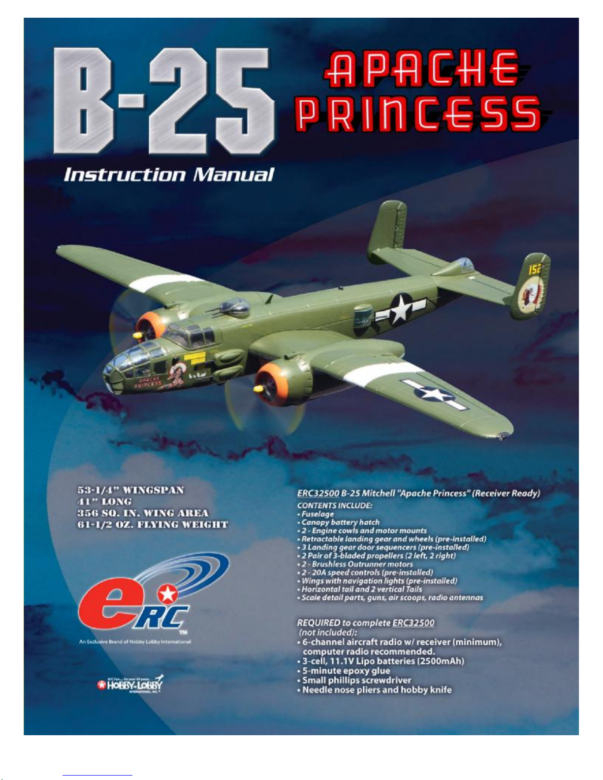
Before starting, use the contents list to take an inventory and make sure it is complete.
If any parts are missing or are not of acceptable quality, contact Hobby-Lobby.com
support at 1-866-WE-FLY-RC (1-866-933-5972)
Contents List
¨ Fuselage
¨ Canopy Battery Hatch
¨ 2-Engine Cowls and Motor Mounts
¨ Landing Gear and Wheels (pre-installed)
¨ 3 Landing Gear Door Sequencers (pre-installed)
¨ 2 pair of 3-bladed propellers (2 left, 2 right)
¨ 2-Brushless Outrunner Motors
¨ 2-20A Speed Controls (pre-installed)
¨ Wings with Navigation lights (pre-installed)
¨ Horizontal Tail and 2 Vertical Tails
¨ Scale detail parts, guns, air scoops, radio antennas
Additional Items Required
¨ 6-channel Aircraft Radio w/ Receiver (minimum), Computer radio recommended.
¨ 3-cell, 11.1V Lipo Batteries (2500mAh)
¨ 5-minute Epoxy Glue
¨ Small Phillips Screwdriver
¨ Needle Nose Pliers and Hobby Knife
3
Page 4
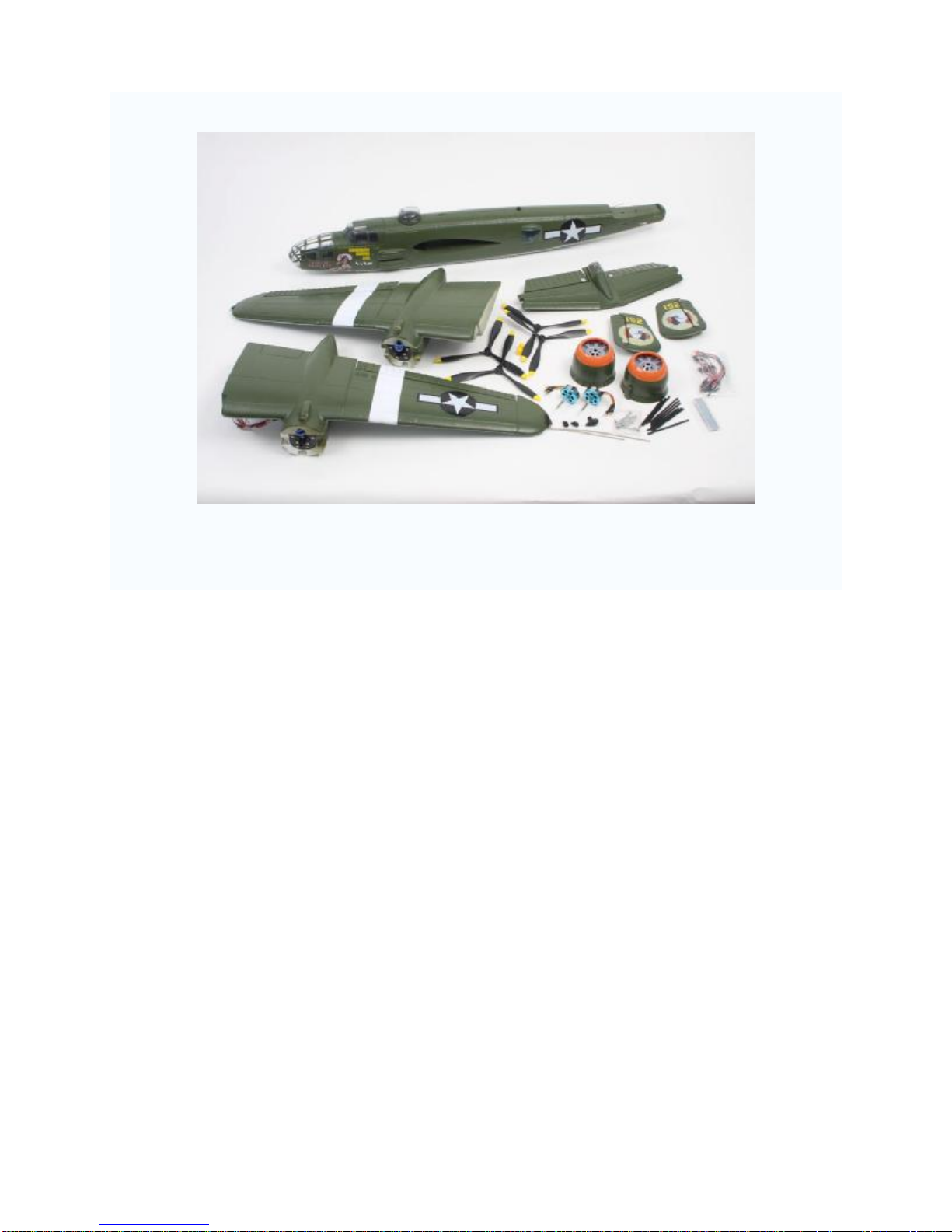
1. This manual will help you assemble your
B-25 Mitchell. Let’s start with the
installation of the brushless motors. Plug
the three motor wires into the three ESC
wires. Do not worry about the plug-in
order; we will check motor rotation in a
later step.
2. Feed the ESC and motor wires back into
the engine nacelle and slide the motor
onto its motor mount.
3. Tighten setscrew with 1.5mm hex wrench
to hold the motor in position.
4. Set the two engine cowls aside till a later
step.
4
Page 5
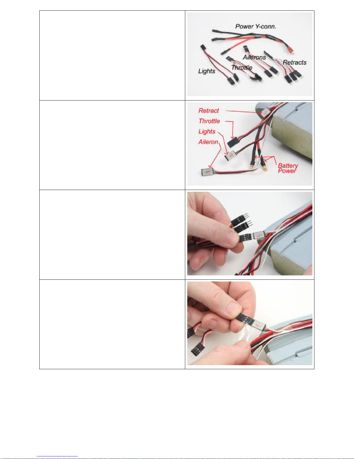
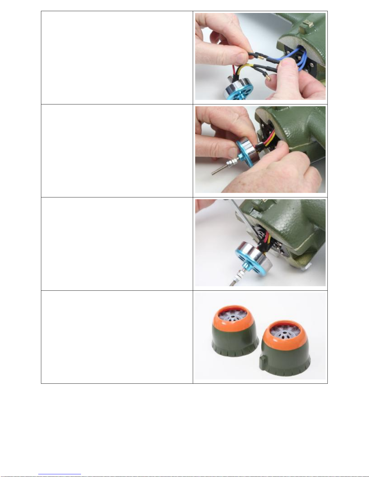
5. Locate the various Y-connectors. See
photo for identification. The triple
connector is for the retracts (Ch. 5). The Y
that does not have the signal wire is for
the lights.
6. Photo shows the root end of a wing panel
and identifies the various connectors.
7. Locate the triple connector and plug in
one leg to the connector labeled “5”.
Please make sure to correctly orient the
signal wire on the connectors.
8. After plugging the wires together, tape the
connection with clear tape to prevent them
from disconnecting.
5
Page 6
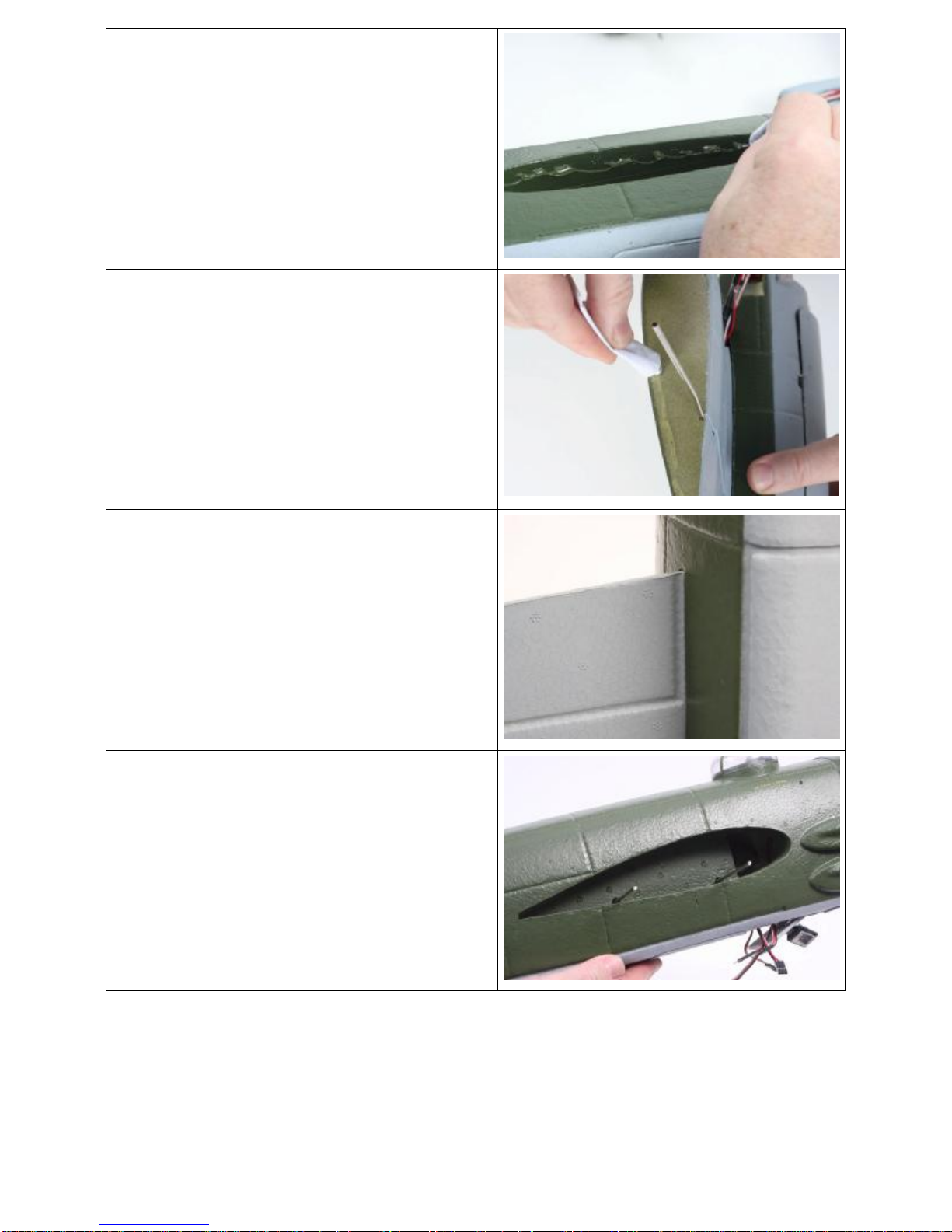
9. Locate the fuselage and apply a bead of
glue to the inside of the main wing
opening.
10. Apply glue to the root end of one main
wing panel.
11. Feed wires into the fuselage at front of the
wing opening and insert the wing into the
fuselage. Make sure that the wing is fully
seated into the opening. When the wing is
in the correct position it will look like the
photo, the flap line will be adjacent to the
fuselage.
12. Insert the wire wing stiffeners from the
other side of fuselage and repeat the
gluing process for the second main wing.
6
Page 7

13. Again, make sure that the wing is fully
seated in the opening as shown in the
photo.
14. Locate the foam rectangle that creates
the wire cover for the bottom of the wing.
Apply a bead of glue around the edge.
15. Install the wire cover as shown in the
photo.
16. Locate the horizontal stabilizer. Please
note the orientation of the bell cranks in
the photo.
7
Page 8

17. Insert the rudder pushrod Z-bend into the
outermost hole on the inboard bell crank
as shown in the photo. Repeat for the
opposite side of the stabilizer.
18. Place the stabilizer in position on the
fuselage and screw into position with the
long screws as shown. Note: it is not
necessary to glue the stab in position.
19. . Snug each screw in position. Do not over
tighten.
20. Attach the elevator pushrod to the control
horn in the outermost hole. After powering
up the radio system and with your control
trims in neutral adjust clevises so that the
elevators are in neutral.
8
Page 9

21. Install the two vertical fins on the
horizontal stabilizer. A small amount of
glue can be used if desired.
22. Screw fin into position as shown.
23. Install the short rudder pushrods to the
outer bell cranks as shown in the photo.
24. Lightly glue the rear screw cover into
position on the bottom of the fuselage.
9
Page 10

25. Temporarily install props on the motors.
PLEASE NOTE: Both left and right hand
props are provided in the kit. We recommend
that the B-25 prop rotation be setup with the
tips of the props rotating toward the wingtips
at the top of their rotation. This means that
from the pilots seat the right engine is rotating
clockwise and the left engine counter
clockwise. If either motor is not turning in the
correct direction, swap any two of the three
motor wires to reverse its direction.
26. After removing the props, install the
engine cowls. Three small black screws
are provided for each cowl and wooden
cowl mounting blocks are pre-installed on
the nacelles.
27. Make sure that the cowl in centered
correctly and the motor shaft turns freely,
then screw into position.
28. Re-install the propellers with the right
hand rotation prop on the right motor and
the left hand rotation one on the left motor.
29. Use a flat washer, lock washer and a nut
to hold each prop.
10
Page 11

30. Screw plastic prop hub to the shaft of the
motor as shown.
31. Locate the injection molded detail parts.
Glue the cockpit air intakes in place with a
small amount of glue.
32. The fin aerial is installed on the top of the
fuselage behind the ball turret.
33. The teardrop antenna is glued in place on
the bottom of the fuselage behind the
nose gear door.
11
Page 12

34. Make pilot holes for the gun barrels with a
thin Phillips screwdriver or length of music
wire. Install gun barrels as shown.
35. Make pilot hole for side gun blister barrel
and install as shown.
36. Install two gun barrels in tail position.
37. Using a body reamer, create holes in the
top turret to accept the gun barrels.
12
Page 13

38. Install barrels in turret.
39. Apply a thin bead of glue to the edge of
the nose greenhouse and install on
fuselage. Use the artwork as a guide to
orientation.
40. With model on its back, mark a point that
is 2-1/2” back from the leading edge of the
wing next to the fuselage. This is the CG
for this model. All initial flights should be
flown with the CG no further aft than this.
After test and trim flights adjust the CG to
suit your flying style.
41. Install your radio receiver being careful to
plug each connector to the proper
channel.
13
Page 14

42. Install the power Y-conn to each ESC
making sure that you plug the red-to-red
and black-to-black. Feed the Deans plug
into the cockpit area of the fuselage.
43. The flight battery is located under the
cockpit. Lift from the rear to remove. A
3-cell Lipo battery of approx. 2500mAh is
about right for size and weight.
44. Each landing gear sequencer controls
one gear door and one gear leg. The three
plugs connect with the signal wire to the
rear of the sequencer (away from label).
45. Make sure that the sequencer and motor
wires are neatly tucked away so that they
do not interfere with the landing gear
wheel when the gear is retracted.
14
Page 15

46. When the landing gear is retracted any
wires should not obstruct the wheel.
47. When the gear is in the down position it
should lock so that it does not collapse
under load.
48. With the model upside down and your
transmitter turned ON with the throttle in
the OFF position; plug a 3-cell Lipo battery
to the Deans plug to power up the system.
Check that each control surface is working
with the correct stick movement and in the
correct direction, adjust as necessary
49. The B-25 includes three landing gear
sequencing modules, one for each gear
location.
15
Page 16

50. The landing gear retracts at a scale like
speed.
51. Once the gear is completely retracted the
gear doors are commanded to close.
52. Each gear door closes at a scale like
speed
53. Once completely closed they are ready to
reverse the operation for landing.
16
Page 17

Recommended Control Throws
Ailerons Low Rate 5/16" Up and Down
High Rate 1/2" Up and Down
Elevator Low Rate 5/16" Up and Down
High Rate 1/2" Up and Down
Rudder 1/4" Both Directions
Center of Gravity 2-1/8"- 2-1/2" Back from the wing leading edge at the root
Preflight
If you are new to flying R/C aircraft, or a seasoned modeler, we recommend you have a
fellow R/C modeler help you with the first flight. Some items you will need to complete
on your first preflight are:
1. Aircraft assembled correctly and ready for flight.
2. All control throws and expos are set per this manual.
3. Transmitter fully charged and on correct model.
4. Aircraft balances at the recommended location. (2-1/2” aft of wing Leading Edge)
5. Flight Batteries are fully charged and secure.
6. All electronics are operating correctly, proper direction, and secure.
7. Complete a radio Range Check per your radio manual.
8. Balance propeller and make sure it is secure.
9. Wait for a calm or light wind day for first flights.
10. If you are new to R/C flying, consider having an accomplished flyer make the first
flight and trim the aircraft. A buddy-box training system is also very helpful.
Flying
The B-25 has very good ground handling character due to its wide stance tricycle
landing gear. This makes taxi and take-off an easy task. Point the nose into the wind
and smoothly advance the throttle, use a little rudder to maintain a straight line and as
the speed increases ease back on the elevator for a smooth lift off. Once the gear are
clear hit the retract switch and watch the gear slowly come up and then the gear doors
swing closed. The flight is scale looking with moderate speed, climb is strong; the two
counter rotating props provide a lot of thrust without the associated torque. Mild
aerobatics can be performed, loops, rolls and inverted are possible but not particularly
scale. Touch-and-go’s are a joy, set up on the runway and drop the gear, ease back on
the throttles and lightly touch down, feed in full throttle and ease back into the sky.
Landings are best accomplished by maintaining a little power completely through the
touch down. The working position lights allow you to continue flying right up to dusk.
Happy Landings!
2008 Official Academy of Model Aeronautics National Model Aircraft Safety Code
17
Page 18

GENERAL
1. A model aircraft shall be defined as a non-human-carrying device capable of sustained flight in
the atmosphere. It shall not exceed limitations established in this code and is intended to be used
exclusively for recreational or competition activity.
2. The maximum takeoff weight of a model aircraft, including fuel, is 55 pounds, except for those
flown under the AMA Experimental Aircraft Rules.
3. I will abide by this Safety Code and all rules established for the flying site I use. I will not willfully
fly my model aircraft in a reckless and/or dangerous manner.
4. I will not fly my model aircraft in sanctioned events, air shows, or model demonstrations until it
has been proven airworthy.
5. I will not fly my model aircraft higher than approximately 400 feet above ground level, when within
three (3) miles of an airport without notifying the airport operator. I will yield the right-of-way and
avoid flying in the proximity of full-scale aircraft, utilizing a spotter when appropriate.
6. I will not fly my model aircraft unless it is identified with my name and address, or AMA number,
inside or affixed to the outside of the model aircraft. This does not apply to model aircraft flown
indoors.
7. I will not operate model aircraft with metal-blade propellers or with gaseous boosts (other than
air), nor will I operate model aircraft with fuels containing tetranitromethane or hydrazine.
8. I will not operate model aircraft carrying pyrotechnic devices, which explode, burn, or propel a
projectile of any kind. Exceptions include Free Flight fuses or devices that burn producing smoke
and are securely attached to the model aircraft during flight. Rocket motors up to a G-series size
may be used, provided they remain firmly attached to the model aircraft during flight. Model
rockets may be flown in accordance with the National Model Rocketry Safety Code; however,
they may not be launched from model aircraft. Officially designated AMA Air Show Teams (AST)
are authorized to use devices and practices as defined within the Air Show Advisory Committee
Document.
9. I will not operate my model aircraft while under the influence of alcohol or within eight (8) hours of
having consumed alcohol.
10. I will not operate my model aircraft while using any drug which could adversely affect my ability to
safely control my model aircraft.
11. Children under six (6) years old are only allowed on a flightline or in a flight area as a pilot or
while under flight instruction.
12. When and where required by rule, helmets must be properly worn and fastened. They must be
OSHA, DOT, ANSI, SNELL or NOCSAE approved or comply with comparable standards.
RADIO CONTROL
1. All model flying shall be conducted in a manner to avoid over flight of unprotected people.
2. I will have completed a successful radio equipment ground-range check before the first flight of a
new or repaired model aircraft.
3. I will not fly my model aircraft in the presence of spectators until I become a proficient flier, unless
I am assisted by an experienced pilot.
4. At all flying sites a line must be established, in front of which all flying takes place. Only personnel
associated with flying the model aircraft are allowed at or in front of the line. In the case of
airshows demonstrations straight line must be established. An area away from the line must be
maintained for spectators. Intentional flying behind the line is prohibited.
5. I will operate my model aircraft using only radio-control frequencies currently allowed by the
Federal Communications Commission (FCC). Only individuals properly licensed by the FCC are
authorized to operate equipment on Amateur Band frequencies.
6. I will not knowingly operate my model aircraft within three (3) miles of any preexisting flying site
without a frequency-management agreement. A frequency management agreement may be an
allocation of frequencies for each site, a day-use agreement between sites, or testing which
determines that no interference exists. A frequency-management agreement may exist between
two or more AMA chartered clubs, AMA clubs and individual AMA members, or individual AMA
members. Frequency-management agreements, including an interference test report if the
agreement indicates no interference exists, will be signed by all parties and copies provided to
AMA Headquarters.
7. With the exception of events flown under official AMA rules, no powered model may be flown
outdoors closer than 25 feet to any individual, except for the pilot and located at the flightline.
18
Page 19

8. Under no circumstances may a pilot or other person touch a model aircraft in flight while it is still
under power, except to divert it from striking an individual.
9. Radio-controlled night flying is limited to low-performance model aircraft (less than 100 mph). The
model aircraft must be equipped with a lighting system which clearly defines the aircraft's attitude
and direction at all times.
10. The operator of a radio-controlled model aircraft shall control it during the entire flight, maintaining
visual contact without enhancement other than by corrective lenses that are prescribed for the
pilot. No model aircraft shall be equipped with devices which allow it to be flown to a selected
location which is beyond the visual range of the pilot.
PARK FLYER SAFE OPERATING RECOMMENDATIONS
• Inspect your model before every flight to make certain it is airworthy.
• Be aware of any other radio frequency user who may present an interference problem.
• Always be courteous and respectful of other users of your selected flight area.
• Choose an area clear of obstacles and large enough to safely accommodate your flying activity.
• Make certain this area is clear of friends and spectators prior to launching your aircraft.
• Be aware of other activities in the vicinity of your flight path that could cause potential conflict.
• Carefully plan your flight path prior to launch.
• Abide by any and all established AMA National Model Aircraft Safety Code.
WARNING – THIS IS NOT A TOY!
Radio controlled model aircraft are capable of inflicting serious injury and/or property damage if not assembled, operated, and
maintained in a competent and safe manner. If you are not already experienced with radio controlled models, we strongly suggest
Hobby-Lobby guarantees this kit to be free from defects in both material and workmanship at the date of purchase. This warranty
does not cover any component parts damaged by use or modification. In no event shall Hobby-Lobby’s liability exceed the original
that you find an experienced modeler to assist you.
Warranty
cost of the purchased kit.
Completely read through this manual before starting construction.
Hobby Lobby International, Inc.
5614 Franklin Pike Circle
Brentwood, TN 37027
1-866-WE-FLY-RC
(1-866-933-5972)
www.hobby-lobby.com
19
 Loading...