

Page 1

Albatros DVa
Wingspan: 52 in. (1325mm)
Length: 41 in. (1045mm)
Wing Area: 723 in². (46.65dm²)
Flying Weight: 60 oz. (1.70kg)
Wing Loading 11.95 oz/sq. ft.
Center of Gravity 2.6 in. (66mm) back from LE top wing
1
Page 2

Additional Items Required
¨ 4-channel Aircraft Radio w/ Receiver (minimum)
¨ 3 cell Lipo battery 2100-2500mAh
¨ (1) Hitec HS-322 servo
¨ (2) eRC 8g servos
¨ (1) eRC 9g metal gear servo
¨ (2) 12” servo wire extensions
¨ eRC Brushless 45 amp ESC w/SBEC
¨ eRC Brushless BL25 Motor
¨ APC 12x6E Propeller
¨ 5-minute Epoxy Glue
¨ Thin CA Glue
¨ Phillips screwdriver
¨ Hex Drivers
¨ Needle Nose Pliers
¨ Hobby Knife
¨ Soldering iron and electrical solder
2
Page 3

1. Install the full size servo for the elevator in
the fuselage. Place the output shaft end of
the servo toward the tail of the airplane.
2. Install the 9g metal gear servo for the
rudder in the fuselage. Place the output
shaft end of the servo toward the tail as
well.
3. Before installing the servo arms, slip the
pushrods into the fuselage and attach “Zbend” end to servo arm.
4. Locate the horizontal stabilizer and the
CA hinges.
5. Insert CA hinges into pre-cut slots in
trailing edge of the horizontal stabilizer.
Insert the hinge 1/2 way into the surface
and put a pin through the hinge to keep it
centered.
6. Slip the elevator onto the CA hinges,
leave a small gap between elevator and
stabilizer.
7. Make sure that the elevator has the
mounting location for the elevator horn on
the right side of the center. The photo
shows the stabilizer from the top view.
8. Check that the elevator is centered on the
stabilizer and that the gaps are even
before you apply the CA to the hinges.
9.
3
Page 4

10. If there is too much wood showing on the
top of the stabilizer, iron on a scrap of the
matching covering from the spare covering
provided.
11. Slide the horizontal tail into the slot in the
fuselage and center. Do Not Glue yet.
12. Locate the vertical fin and rudder and
hinge together in the same manner as the
horizontal stabilizer and elevator.
13. Insert the vertical fin and rudder into the
slot on the top of the fuselage. There are
tabs on the bottom of the vertical fin that
must engage in slots on the horizontal
stabilizer.
14. When satisfied with the fit CA the joints
using thin CA and a small tip to keep
things neat.
15. Screw the nylon control horns to the
elevator and rudder. The elevator horn is
on the bottom right of the elevator and the
rudder is on the left side of the rudder.
Use the 6 shorter screws that look like the
photo to the right.
4
Page 5

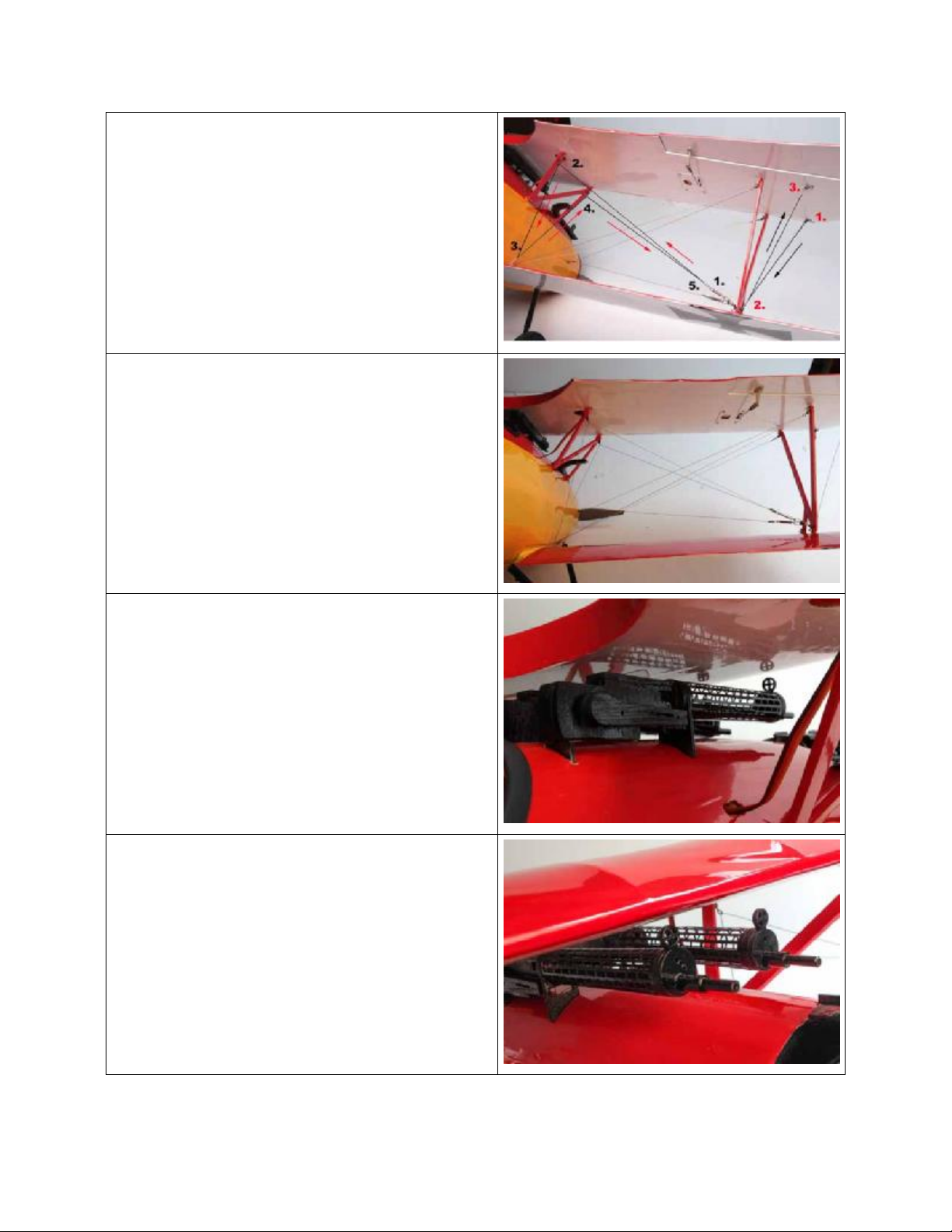
16. Single 35” piece of stranded wire is for the
tail brace. The other pairs of wires will be
used later for the main rigging of the
wings.
17. Locate the tail brace parts shown in photo.
You will also need the 35” wire and 2
crimp tubes.
18. Install the U shaped metal over the tail
skid and bolt in place with a swivel on
each side.
19. Slide the wire through one of the crimp
tubes then through the swivel and back
through the crimp. Lock in place by
crimping the tube with a pair of pliers.
20. Thread the wire through the pre-drilled
holes in stabilizer and fin and finish by
repeating the process on the other crimp
21. Attach the pushrods to the rudder and
elevator and adjust to neutral position.
22. Remove the servo hatches from the
bottom of the upper wing.
23. Test fit the micro servo making sure that
the servo arm does not bind on the
opening of the servo hatch.
24. If the servo arm is not centered in the
opening, adjust by cutting the wood
mounting ears for proper fit.
5
Page 6

25. With servo mounted on hatch, extend the
length of the servo wire with a 12”
extension. Tape the connection so that it
cannot be pulled loose.
26. Tie the male plug end of the extension to
the pull string located in the wing.
27. Cut open the hole on the bottom of upper
wing near the cabane strut attachment.
28. Fish the servo extension through the wing
and out the exit hole.
29. Repeat this process for the other aileron.
30. Screw each hatch in place using 4 small
washer head screws.
31. Install the CA hinges in the leading edge
of the ailerons. Insert them 1/2 way in the
control surface and pin the center to
prevent the hinge being further inserted.
6
Page 7

32. Check the hinge gap and keep it small.
Using the shaft of the pin as a guide is a
good idea.
33. When satisfied with the fit of the aileron,
CA it in place with a quick shot of thin CA
glue. Flex the control surface down and
add 3 drops to each hinge then flex
aileron up and repeat the process.
34. Nip the excess screw length off with a pair
of side cutters or a Dremel cut-off wheel.
35. Locate the remaining 2 nylon control
horns and the longer screws and install in
the pre-drilled locations on each aileron.
7
Page 8

36. The photo at the right shows the parts
needed to assemble the landing gear. Not
shown in the photo are the 3 wheel
collars, you will need them as well.
37. Slide one wheel onto axel and then one of
the wheel collars.
38. Next slip on one of the landing gear leg
attachment parts onto the axel with the
bends leaning away from the wheel as
shown.
39. Install the landing gear legs onto the
attachment part.
40. Slide the landing gear spreader bar with
its airfoil facing in the direction of flight.
The longer leg is the rear leg.
41. Slide on the other landing gear attachment
part followed by another wheel collar and
tighten.
42. Install the remaining landing gear legs.
8
Page 9

43. Slip on the second wheel and the final
wheel collar and tighten, make sure that
the wheels rotate freely.
44. The assembly should look like the photo to
the right and is ready to install into the
slots in the fuselage.
45. Carefully install the wire ends into the slots
on the fuselage and slip them fully into the
pockets.
46. Locate the 4 ply inserts as shown.
47. Insert one ply spacer into each of the
slots. Do not apply glue, we will add a few
drops of CA when we have them all
complete.
9
Page 10

48. You may need to use the end of a piece of
ply to aid in inserting the spacers, they are
a tight fit.
49. Once fully inserted apply a few drops of
thin CA to retain the spacers.(See photo)
50. If you are using the recommended eRC
BL25 motor, you will need to install the
laser cut ply mounting disc to the rear of
the motor instead of the X-mount that
came with the motor.
51. The motor shaft must be shortened by
about 1/4" so that the rear of the collet
adapter touches the anodized motor case.
52. If this is not done the spinner will have too
large a gap behind it.
53. Slide the ESC into the fuselage and screw
the motor mount to the firewall with the
supplied allen head screws.
10
Page 11

54. The installation should look like the photo
to the right.
55. With the dummy motor installed, the
battery hatch installs and is held in place
with magnets.
56. Install cabane struts on fuselage. Use
small machine screw, washer and nut.
57. Cabane should be mounted to the bottom
side of the supports as shown.
58. Install the outboard struts to the bottom of
the upper wing. Mount them to the outside
of the supports.
59. The installation should consist of. A screw
through the strut and then the support.
Slip a swivel onto the screw then a washer
followed by the nut, snug in place.
60. Photo shows the two additional swivels
that are installed with small wood screws
to the outboard underside of the upper
wing. The location is pre-drilled.
11
Page 12

61. In addition to the cable you will need this
hardware.
62. Machine screws, washers and nuts to
attach struts to wings and fuselage
63. Turnbuckles, cable connectors and cable
crimps to attach cable and adjust cables.
64. Locate the cables and separate into
groups shown.
65. Two 21” pieces at outboard wing tips
66. Bottom wing strut attachment front hole.
67. From the outside of the strut insert screw
with swivel through strut an strut
attachment. Slide another swivel to the
screw then a washer and nut.
68. With a screw and nut attach the base of 2
cable connectors to the top of the swivel.
69. Take one of the 74” cables and attach a
turnbuckle as shown.
70. Insert wire end through crimp, then
through eye on turnbuckle, back through
crimp in opposite direction, make a loop
and insert cable through crimp in the same
direction again.
71. Snug up cable and crimp the tube with a
pair of pliers.
72. Photo shows assembly uncrimped.
12
Page 13

73. Install swivel on side of fuselage nose with
washer head wood screw.
74. Unscrew the turnbuckle so that you will
have adjustment room later.
75. Start at the location shown in photo.
76. Slip one crimp on cable and thread cable
through swivel on nose and back through
crimp.
77. Next the cable goes through the upper
rear swivel then down to loop at root of
lower wing, finishing at upper front strut.
78. Slip a crimp on cable before inserting in
swivel, then back through the crimp. The
same process as at the turnbuckle.
79. DO NOT TIGHTEN AND CRIMP AT THIS
TIME
80. Repeat process on opposite wing.
81. Install one turnbuckle to cable connector
at outboard lower strut as shown.
82. Take one of the 51” cables and connect it
to the turnbuckle with crimp as before.
13
Page 14
83. Thread cable through rear upper cabane
swivel, then through a cable crimp, then
the lower wing root connector and back
through the crimp before going to the
upper cabane swivel and back to the
turnbuckle at the base of the outboard
strut.
84. Make sure that you have adjustment room
on the turnbuckle. Snug up the cables
before crimping.
85. Using the 21” cables create the outboard
rigging starting at the upper front swivel.
86. Three crimps will be used. One at the
beginning, middle and end. No
turnbuckles are used here.
NOTE: When complete you will have 2
extra turnbuckles for spare parts in case of
loss.
87. When adjusting the rigging it is very
important to adjust it evenly and make
sure not to warp the wing structure. It is
possible to warp the wings to the extent
where control with the flight surfaces may
be impossible.
VERY IMPORTANT: Once wires are adjusted
it is a very good idea to put a dab of glue
(UHU Por or similar) on each of the nuts and
the turnbuckle adjustments.
88. Slip pre-made machine guns into position
on mounting tabs. A touch of glue like Uhu
Por will help hold it in place.
14
Page 15

89. The spinner is vacuformed and the
Low Rate= 7/8” Each Direction
backplate is aluminum. Both must be
balanced as well as the 12x6 APC E-prop.
90. For best results use a prop balancer.
Aileron Control Throws
High Rate= 5/8” Up and 1/2" Down
Low Rate= 3/8” Up and 1/4" Down
Rudder Control Throws
High Rate= 1-1/8” Each Direction
Elevator Control Throws
High Rate= 1” Up and Down
Low Rate= 3/4" Up and Down
CG
2.6” back from the leading
edge of the upper wing
Battery
3-cell 2100mAh Lipo
WARNING – THIS IS NOT A TOY!
Radio controlled model aircraft are capable of inflicting serious injury and/or property damage if not assembled, operated, and
maintained in a competent and safe manner. If you are not already experienced with radio controlled models, we strongly suggest
Hobby-Lobby guarantees this kit to be free from defects in both material and workmanship at the date of purchase. This warranty
does not cover any component parts damaged by use or modification. In no event shall Hobby-Lobby’s liability exceed the original
that you find an experienced modeler to assist you.
Warranty
cost of the purchased kit.
15
Page 16

Hobby Lobby International, Inc.
5614 Franklin Pike Circle
Brentwood, TN 37027
1-866-WE-FLY-RC
(1-866-933-5972)
www.hobby-lobby.com
16
 Loading...