

Page 1
INSTRUCTION MANUAL
Please adjust the C of G (200-212mm) according to
the diagram before you attempt to fly the wing. If you
do not follow the C of G closely, it will crash or
damage to nearby properties or people at your flying
field.
The flight performance will be affected by adding
extra weight on the Teksumo. So you should reduce
any unnecessary weight while assembly. Then you’ll
get the best flying performance!
Recommended Flying Setup
Max servo travel of aileron: 15 degrees up and
15 degrees down (28mm)
Max servo travel of elevator: 15 degrees up and 15
degrees down (28mm)
Do not fly under the conditions as below :
Wind strong enough to make the trees rustle
A street with many trees or street lamps
Close to high voltage electrical wires
High Population density areas .
Cautions for flying
Large gyms, front lawns and parks make excellent
flying areas. Make sure you have permission to fly
and follow safety guidelines set by local authorities.
The calmer the wind, the better!
Note for Storage
Please disconnect the lipo packs when finished flying.
Do not press or crush the airplane when storing .
The best way to store is to hang the airplane to keep
the control surface rigid .
Features:
1. Teksumo is a very popular EPP high speed delta wing
for FPV flying. It is most suitable to fly in a large open
field.
2. Made of high quality EPP material, it is very strong,
durable and easy to fly.
3. Very easy to build, most of the parts are pre-assembled in our factory already.
Product Specifications
Fuselage length: 575mm (22.6in .)
Wingspan: 900mm (35.4in .)
Flying Weight: 500-550g (with battery)
Motor: 2208 KV 1370 or Hk2818 KV1350 (Recommend)
ESC : 15-20 Amp (Recommend)
Propeller: 7050E OR 6050E (Recommend)
Servo: 8g micro servo* 2pcs (Recommend)
Radio: 4 or more channels with computer mixing (Recommend)
Battery: 11.1 V 800-1200mAh Li-po 20C (Recommend)
1
12
4
14
6
10
13
3
2
7
11
5
8
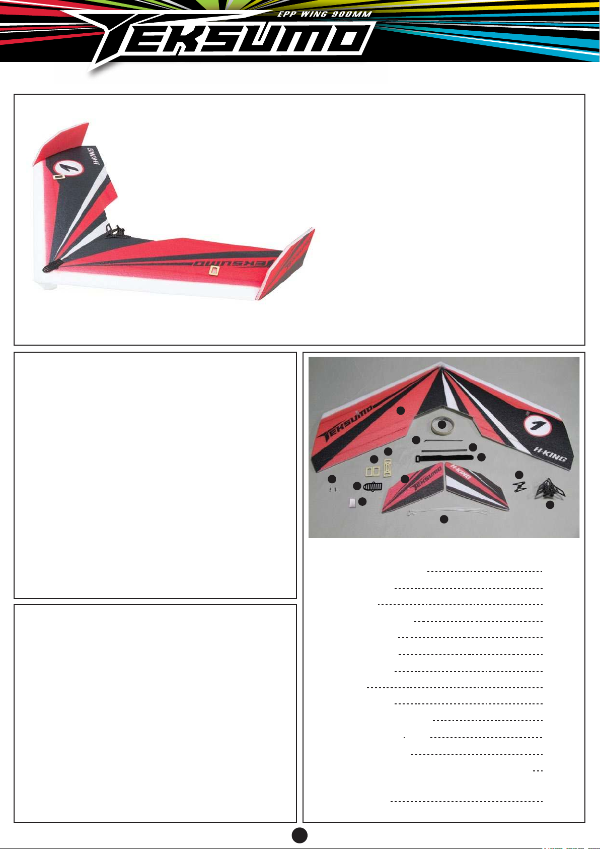
Parts included in the packing
1. Wing (right and left)
2. Wing fences
3. EPP skid
4. Z bend pushrods
5. Control Horns
6. Servo mounts
7. Carbon rods
8. Zip ties
9. Motor mount
10. Push rod connector
11. Battery velcro strap
12. Fiberglass tape
Carbon composite board for Video Camera
13.
(Video camera is not included)
14. Battery tray
9
2 pcs
2 pcs
1 pc
2 pcs
2 pcs
2 pcs
3 pcs
4 pcs
1 pc
2 pcs
1 pc
1 pc
1pc
1pc
1
Page 2
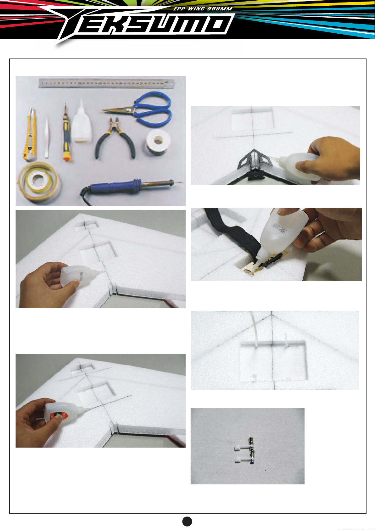
The items below are required for assembly
3. Please ensure the motor mount is true and
levelled with the plane axis. The motor thrust angle
should be aligned to the wing axis otherwise it will
affect the flying performance. Once satisfied about
the fit, apply CA glue to secure it in place.
4. Install the battery holder with velcro tape to the wing
and secure it by using CA glue.
1. Find a flat work bench and place both L & R wings
on top. Align the wing properly and glue it together with
CA glues shown. Use a straight edge and place on top
of the wing to check while the glue set to ensure the
wing is perfectly flat.
2. There are 3 carbon rods supplied in the kit to reinforce the wing joint. Install 2 carbon rods into the
pre-cut slot which located top and bottom as shown in
picture. Then locate the third carbon rod to the wing
bottom as shown. Add CA glue into the slot and let it
dry.
5. Insert the supplied zip tie to the pre-cut hole of the
wing. These zip ties will hold your ESC and RX in the
recess area as shown.
6. Install the pushrod connector onto the farthest hole
on the servo arm
from the servo
output axis.
Then install the
servo arm onto
the servo, please
ensure the servo
arm is in neutral
position. once
statisfied the
setup, tightened
the servo horn screw by a Philips screw driver. Please
follow the same steps for the other wing servo.
2
Page 3
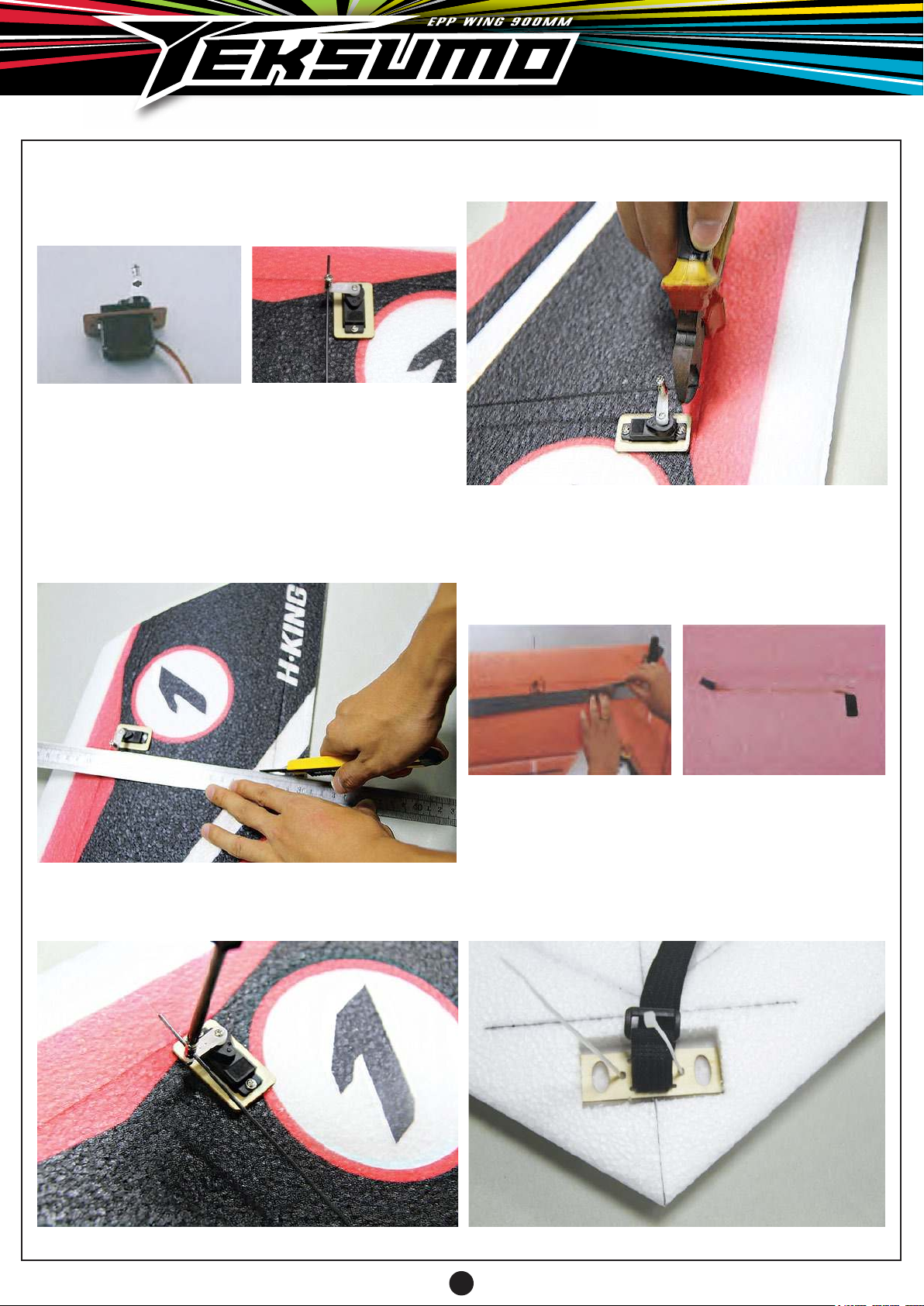
7. Apply CA glue to the servo mount and secure it into
place as shown. Install servo onto the servo mount.
Use two self-tapping screws to secure the servo into
place.
8. Use a straight edge to find out the best possible
location to install the control horn. The pushrod needs
to be perpendicular to the servo and inline with the
servo horn. The holes on the control horn should align
with the hinge line to ensure the travel throws are
symmetrical. Once satisfied about the fitting, use a pen
to mark it and cut a slot just big enough to snug fit the
control horn. The control horn orientation should be
positioned as shown.
10. Use a pliers to cut off the excess and use a file to
round off the edges.
11. Use a pen and a straight edge to draw a line first
from the servo opening on the wing to the mid section
of the wing and then cut a slot as shown to insert the
servo lead. Note: The length of the servo leads may
not be long enough so add two servo extension leads
accordingly on both side of wings.
9. Hook up the control linkages which are supplied in
the kit. Tighten the screw on the pushrod connector and
apply Loctite to prevent from coming loose in flight.
12. As the picture shown, use a knife to cut a servo
wire slot, so that the wire can be easily reached to the
equipment compartment, then insert the servo wire into
the pre-cut slot.
Attention: A Y-type servo lead is not applicable to this
flying wing. A computer radio with delta wing mixing
capabilities is suggested to use on this model.
3
Page 4
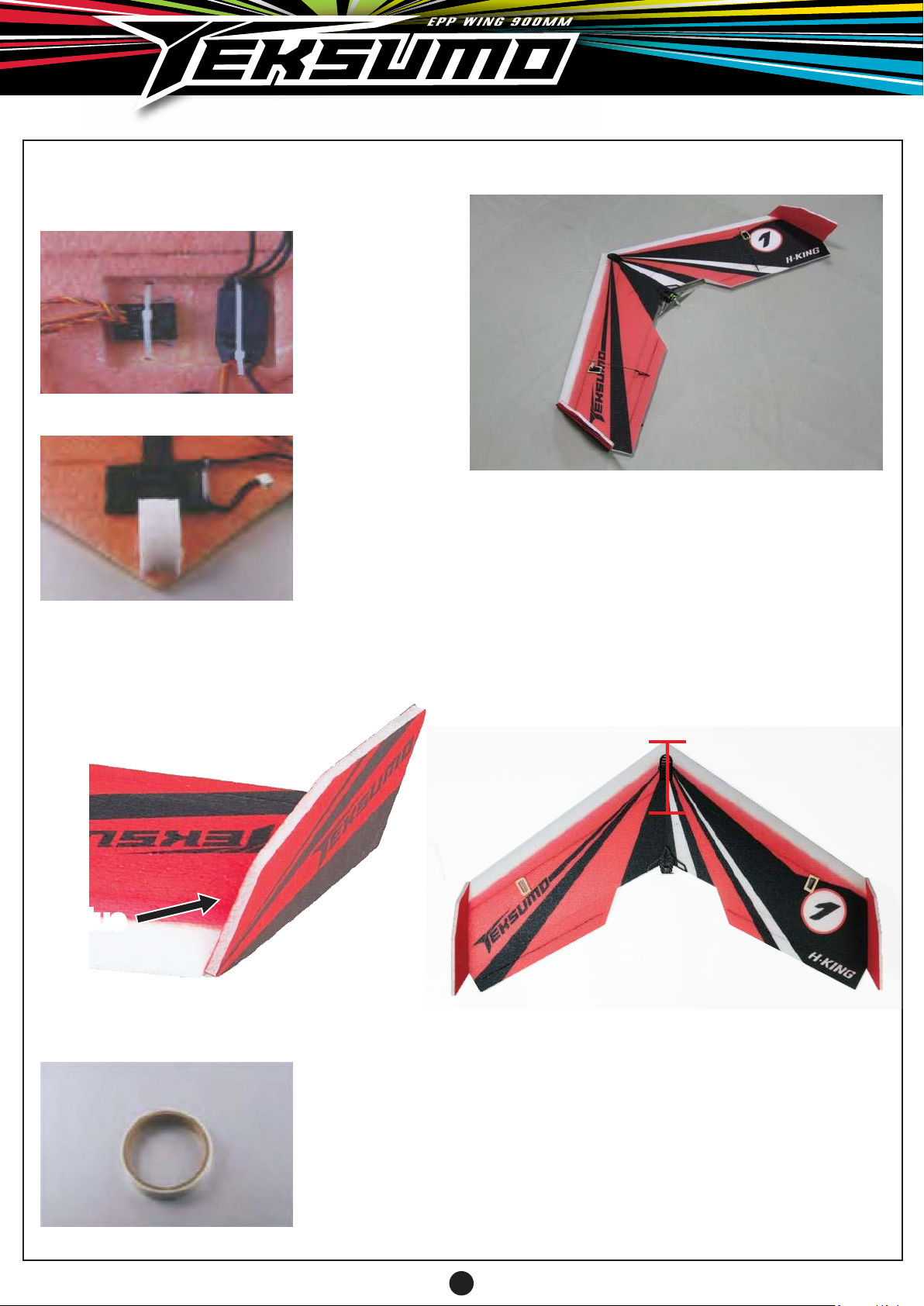
13. Connect the esc and motor, but please confirm
the direction of motor rotation before flying.
14. Connect the servo plug and esc plug to the
receiver, and
then test, finally
using the plastic
band to fix the
receiver into the
equipment
compartment.
15. Install the EPP skid onto the nose of the flying
wing so that it
can prevent from
damaging the
battery or receiver upon landing.
Fix the battery by
using velcro
strap.
FINISHED PRODUCT
NOTE: Please adjust the C of G (200-212mm) according to the diagram before you attempt to fly the wing. If
you do not follow the C of G closely, it will fly in an
uncontrollable manner and it may also causes plane
crash or hitting someone or any properties nearby the
flying field.
16. Install the fins on both wing tip and secure it with
CA glue.
GlueGlueGlueGlueGlue
17. A roll of fiberglass tape is supplied in the kit.
Please use it to
reinforce the
leading edge of
the wing and
some of the areas
on the wing that
need to be reinforced.
The flight performance will be affected by adding extra
weight on the Teksumo. So you should reduce any
unnecessary weight while assembly. Then you’ll get the
best possible flying performance!
200-212mm
ENJOY !
4
 Loading...