

Page 1
H-King Savage Bobber 1000 mm 5ch ARF Version
Page 2
Page 3
FEATURES:
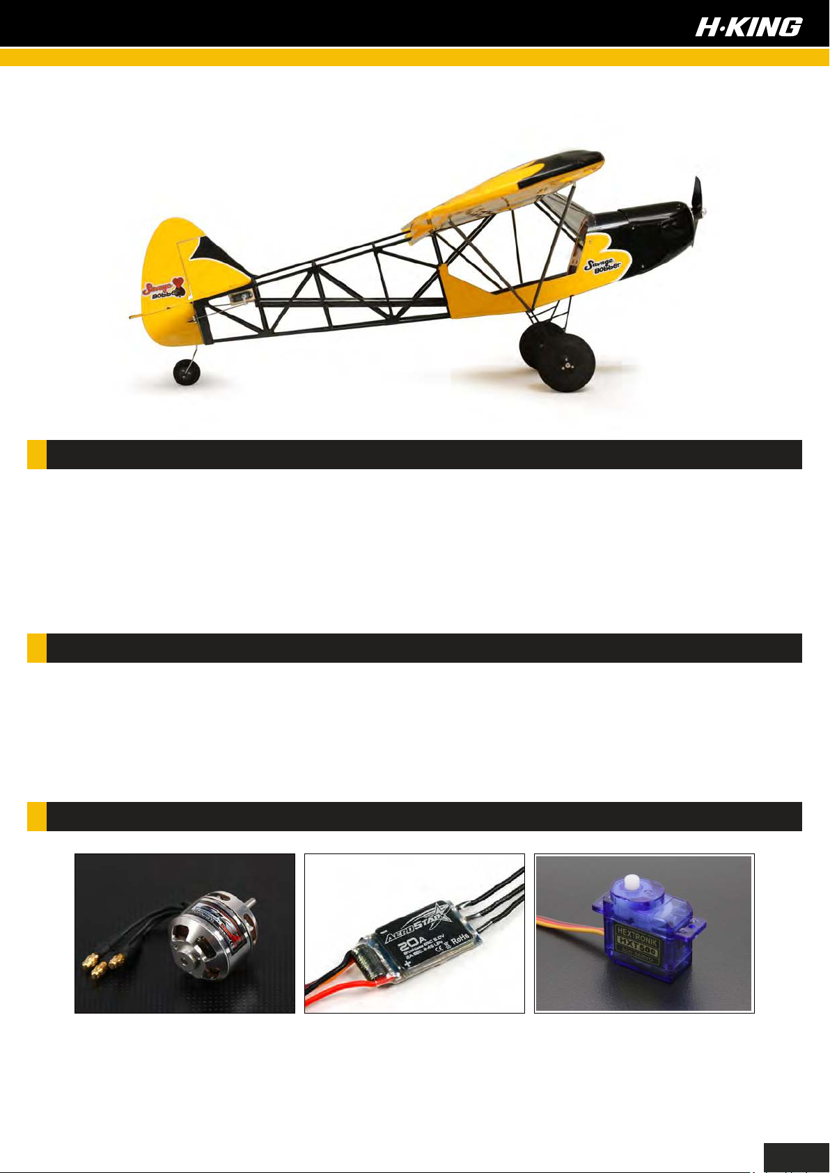
- Skillfully hand-crafted construction
- Crystal clear plastic windshield
- Carbon wing joiner, and wing struts
- Colorful factory-applied self adhesive decals
- Scale wheels with oversized tires
- Wingspan: 1000mm
- All Up Weight w/Battery: 650g depending on
set-up
- Servos: 6 x 3~6g
- Propeller: 8x5
- Factory-applied covering film
- Vacuum formed plastic engine cowling
- High-quality comprehensive hardware
pack
- Pre-slotted hinge pockets
- Length: 700 mm
- Motor: 2826 1130 KV
- ESC: 20A with BEC
- Battery: 1000~1300mAh 3S LiPo
SK3 2826 1130 KV
Brushless Outrunner Motor
SKU: SK3-2826-1130
Aerostar 20A with BEC
SKU: 9164000034-0
HXT500 Micro Servo
1.2kg / 0.10sec / 5g
SKU: HXT500
1
Page 4
1
2
3
5
6
18
4
19
12
8
13
9
10
11
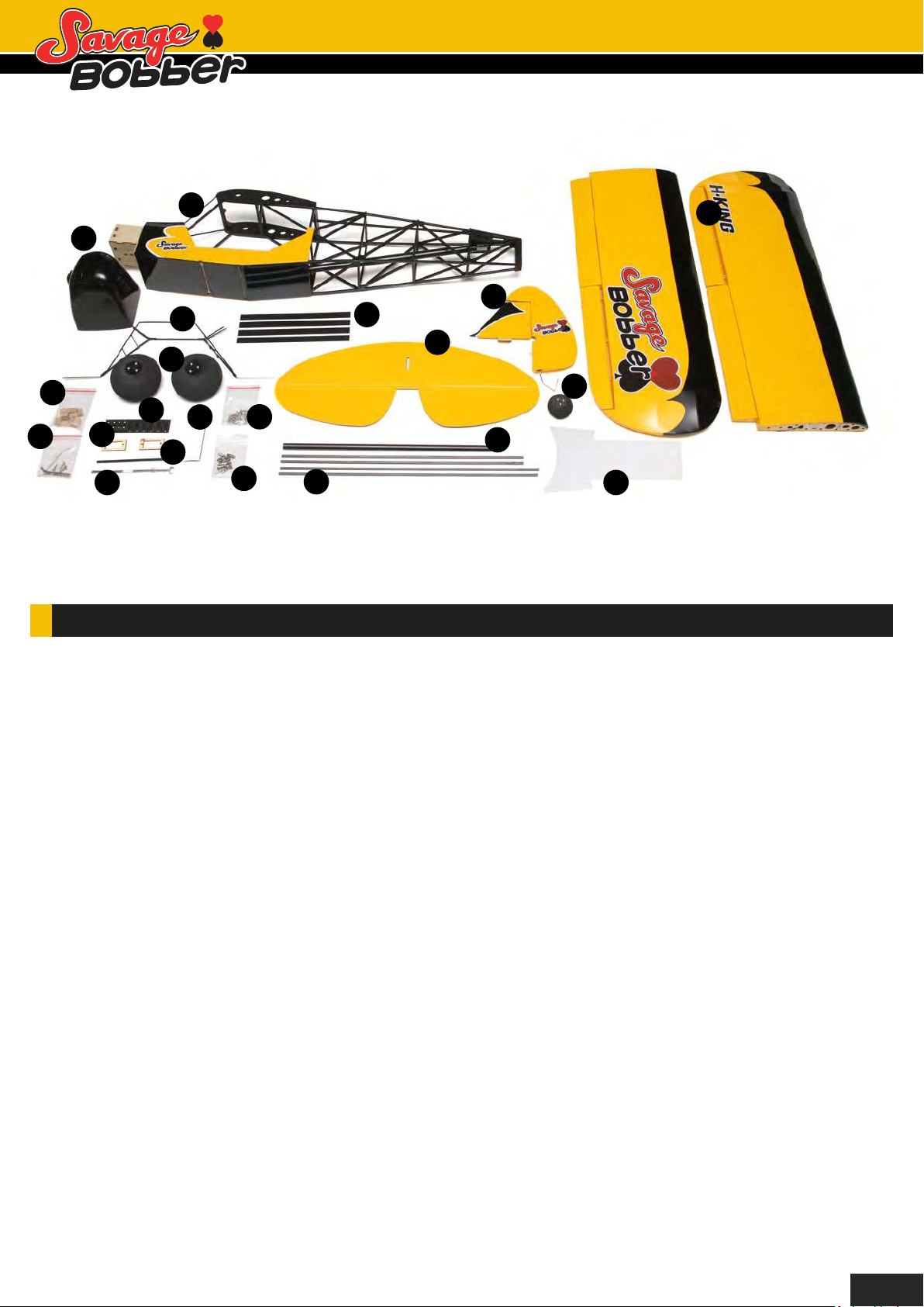
CONTENTS:
1. Fuselage
2. Cowling
3. Vertical stabilizer
4. Horizontal stabilizer
5. Landing gear
6. Main wheels
20
15
14
17
7
16
21
11. Pushrods
12. Servo mounting blocks
13. Wing mounting metal fittings
14. 1.5mm x 6 mm self-tapping screws
15. Wheel collars & pushrod stoppers
16. 8 mm x 265 mm carbon fiber wing joiner
7. Tail wheel
8. Fiber sheets (Control horns and mounting straps)
9. Servo mount spacers
10. 3mm x 25mm carbon fiber wing joiner
17. Carbon fiber wing strut
18. Wing decal sheet
19. Main wings
20. Double sided tape
21. Clear plastic windshield
2
Page 5
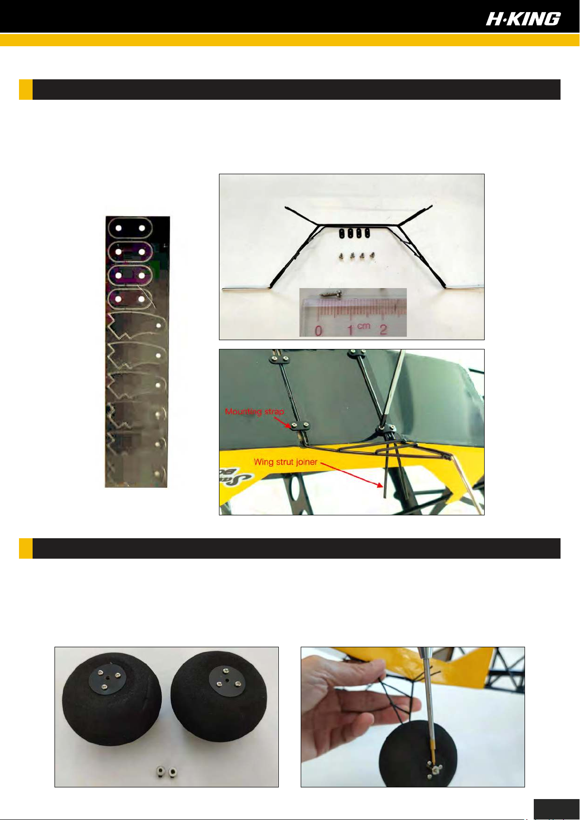
LANDING GEAR INSTALLATION:
Remove the landing gear mounting strap from the supplied fiber sheet and find the M1.5x6 tmm selftapping screws in one of the accessory bags. Attach the wire landing gear to the fuselage using the
self-tapping screws to secure it in place. Note: The set of wing strut joiners on the landing gear
should be positioned towards the rear of the fuselage.
WHEEL INSTALLATION:
Install and secure the set of wheels by using the supplied wheel collars as shown. After installation,
spin the wheels to see if there is any friction and adjust the wheel collars accordingly. If need be,
use a 2.0 mm drill bit to slightly enlarge the hole size or adjust the wheel collars to ensure the
wheels spin freely. Apply a small spot of thread lock glue to the grub screws on the wheel collars to
prevent them from loosening in flight.
3
Page 6
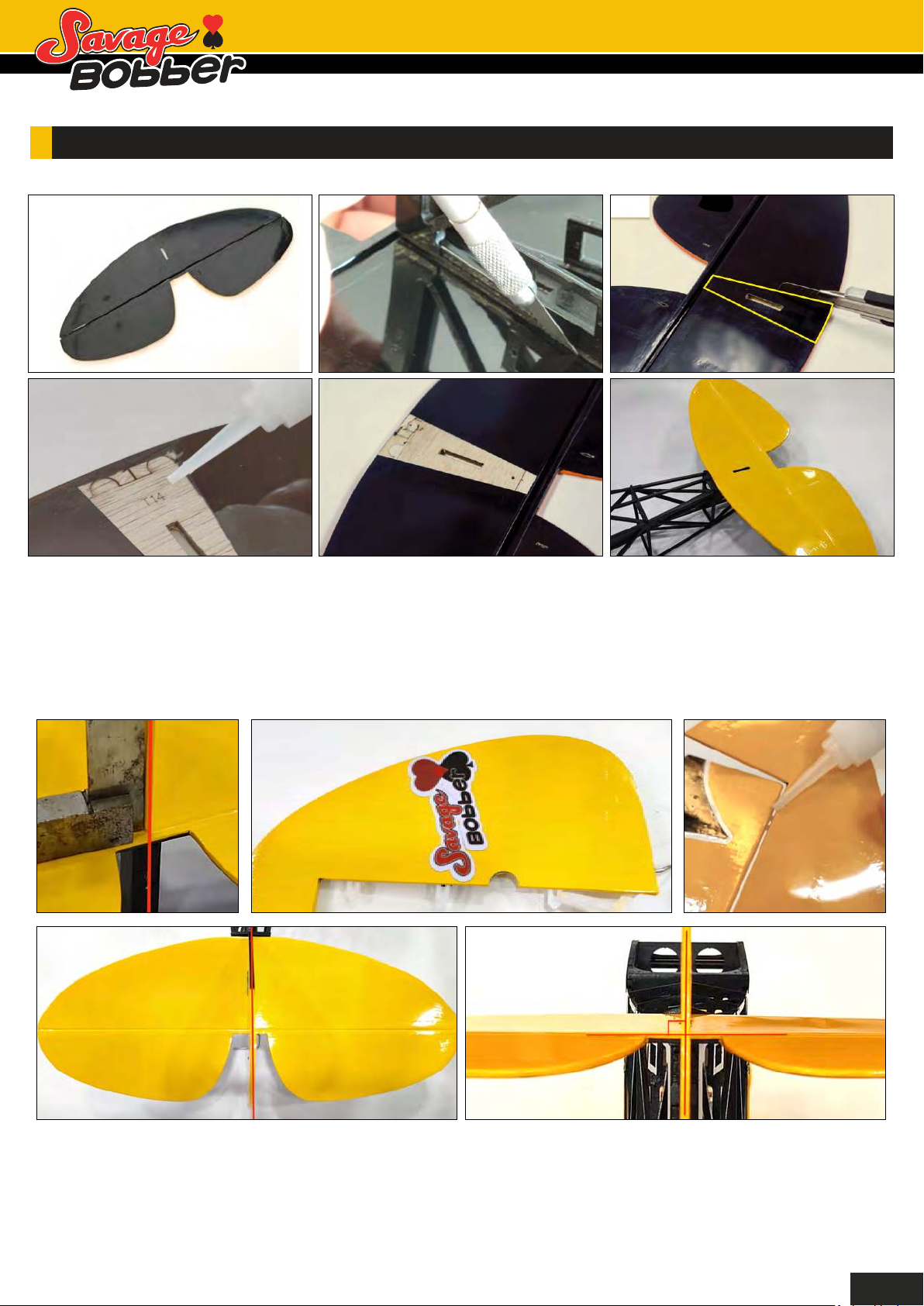
HORIZONTAL STABILIZER AND VERTICAL RUDDER INSTALLATION:
Firstly, dry fit and tape the horizontal tail onto the fuselage. secondly, align the stabilizer accordingly to
ensure it is true and square to the fuselage. Then use a hobby knife and gently cut through the
covering. Finally, peel off the covering and it’s ready for installation. Apply CA glue to the bare wood
area you have exposed on the stabilizer and attach it to the rear of the fuselage.
4
Page 7
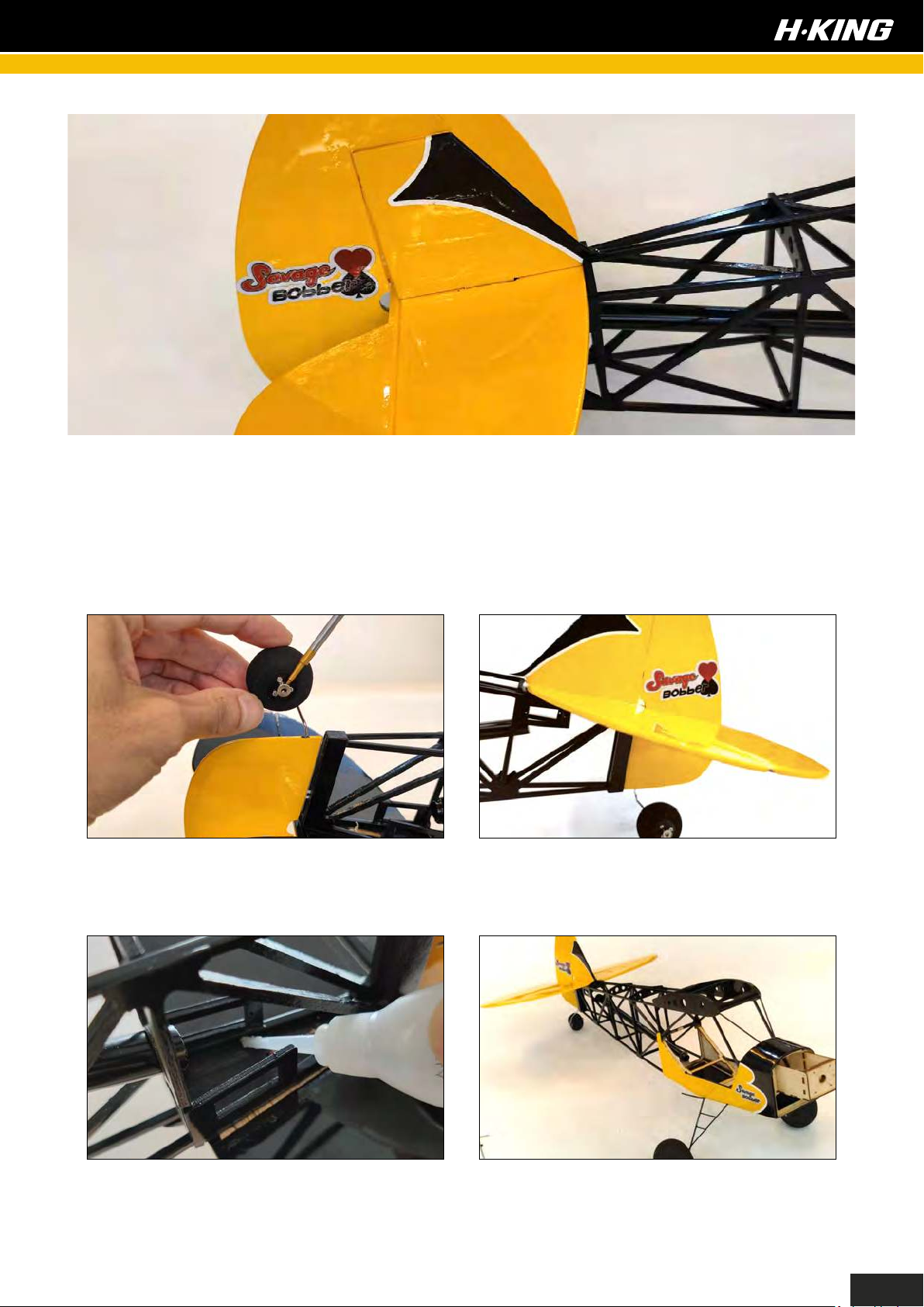
Dry fit the rudder/fin assembly onto the horizontal stabilizer, ensure they are perpendicular to each
other. Once you are satisfied with the fit, apply CA glue to the fin to secure it in place. Then install
hinges half way into the pre-slotted hinge pockets in the rudder by applying a small amount of
thin CA glue as shown, wait until it has throughly dried. Install the rudder to the fin, and slide
the hinges into the hinge pockets on the fin. Use a hobby knife to enlarge the hinge pocket if
needed to allow it to align properly. If the installation looks good, apply a small amount of thin CA
glue to secure it in place. Check frequently if it moves freely as glue sets.
Install the tail wheel onto the rudder landing gear wire and use the supplied wheel collar to lock it in
place. Apply a small amount of thread lock glue to the grub screws to prevent them from loosening
in flight.
At this point, reinforce the joint in the seam
between the stabilizer and the tail structure by
running in a thin layer of medium CA glue.
The empennage and the landing gear setup is
now complete.
5
Page 8
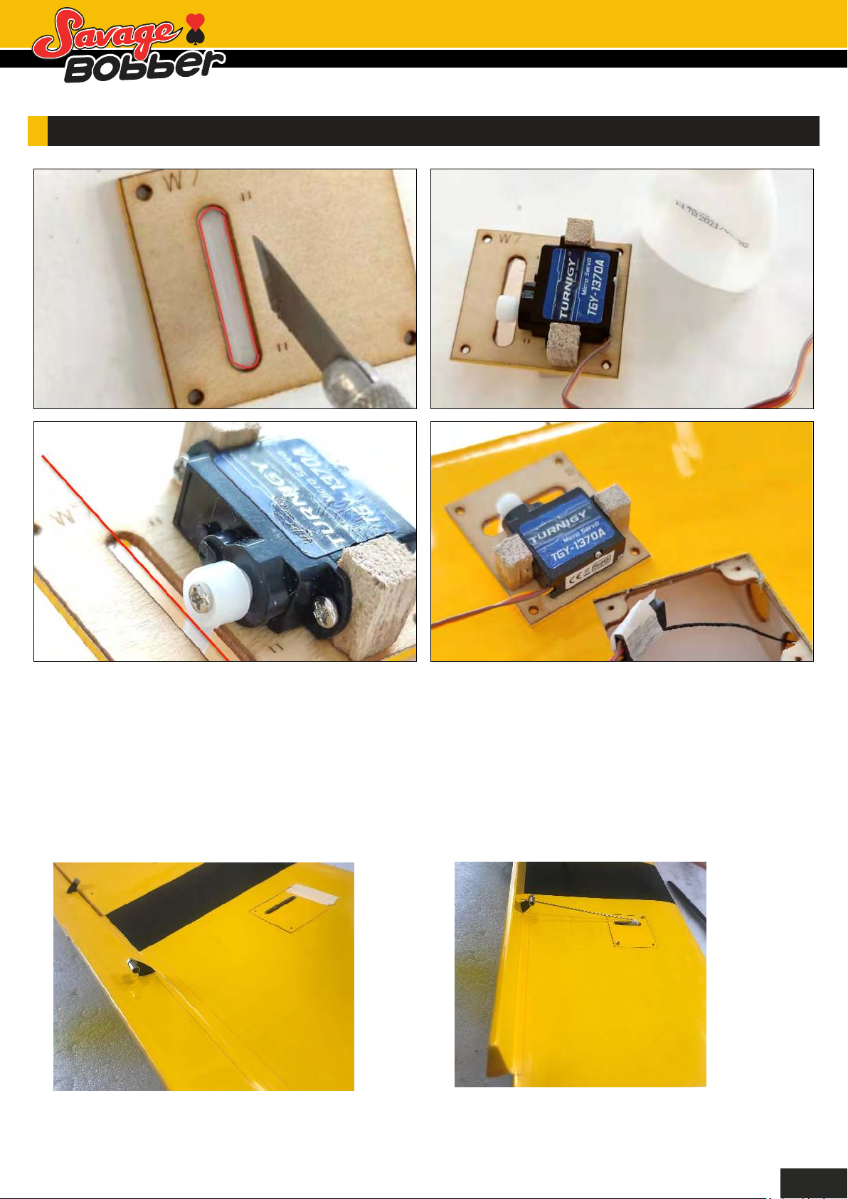
AILERON SERVO & FLAP INSTALLATION:
First, make a cut in the covering at the servo horn opening and trim the area neatly on the servo mounting
plate with a hobby knife as shown. Secondly, position the servo in the center on the servo mounting plate,
and glue the supplied wooden mounting blocks onto the mounting plate as shown. Ensure the servo horn
sits right in the middle of the opening without any interference of the servo arms movement whilst the glue
dries. After that, install the aileron servo by using the self-tapping screws which come with your servo.
Finally, get a piece of masking tape to hold both the servo lead and the piece of thread which is buried
inside the wing together. This will then allow you to slowly pull the servo lead through the wing and out of
the wing root fairly easily. Note: If using 5 or 6g servos then you will need to adjust the servo mounting as
necessary to enable them to fit.
Install the flap servos in the same way as the aileron servos, but please note the difference when fitting the
flap control horns. These are installed in reverse to the normal direction, this is to allow you to achieve a
full 90° movement of the bottom hinged flaps for real slow flying and steep approaches.
6
Page 9
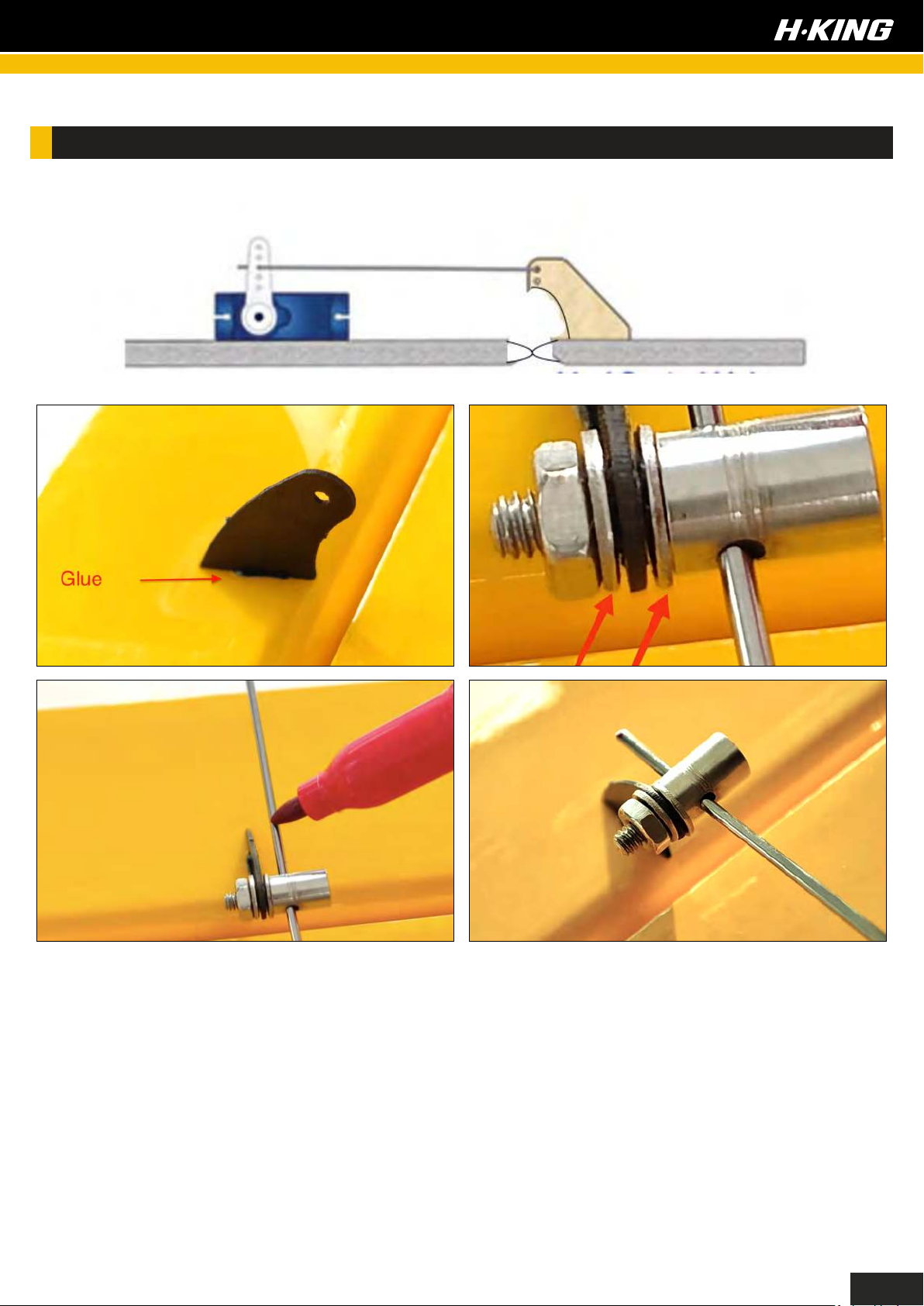
CONTROL HORNS AND PUSHROD LINKAGES INSTALLATION:
Apply medium CA glue to the surface control horn and stick it into the slot as shown. Once the glue
has set, install a supplied pushrod stopper onto the control horn. In order to get the best mechanical
linkage setup, first of all ensure that the servo control horn is perpendicular to the servo case. Then
connect the pushrod to the servo control horn and connect the pushrod stopper as shown. Get a
piece of masking tape to hold the control surface straight and level and then tighten the grub screw
with a hex-key. Apply a small spot of thread lock glue on the grub screw threads, and trim off the
excess pushrod length with a pair of wire cutters.
7
Page 10
FLAP SERVO INSTALLATION:
Repeat the above steps for the flap servo installation.
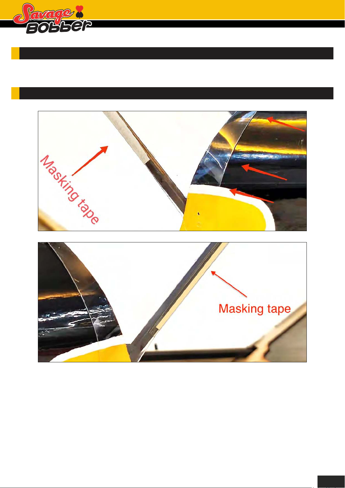
COCKPIT WINDSHIELD INSTALLATION:
Install the factory pre-cut PVC windshield onto the fuselage cockpit area. Use masking tape to hold
the windshield in place on the cockpit frame as shown in the pictures, do this on both sides. Ensure
the PVC sheet is evenly positioned on the turtle deck in front of the cockpit. Adjust the windshield
as necessary to achieve the best fit.
8
Page 11
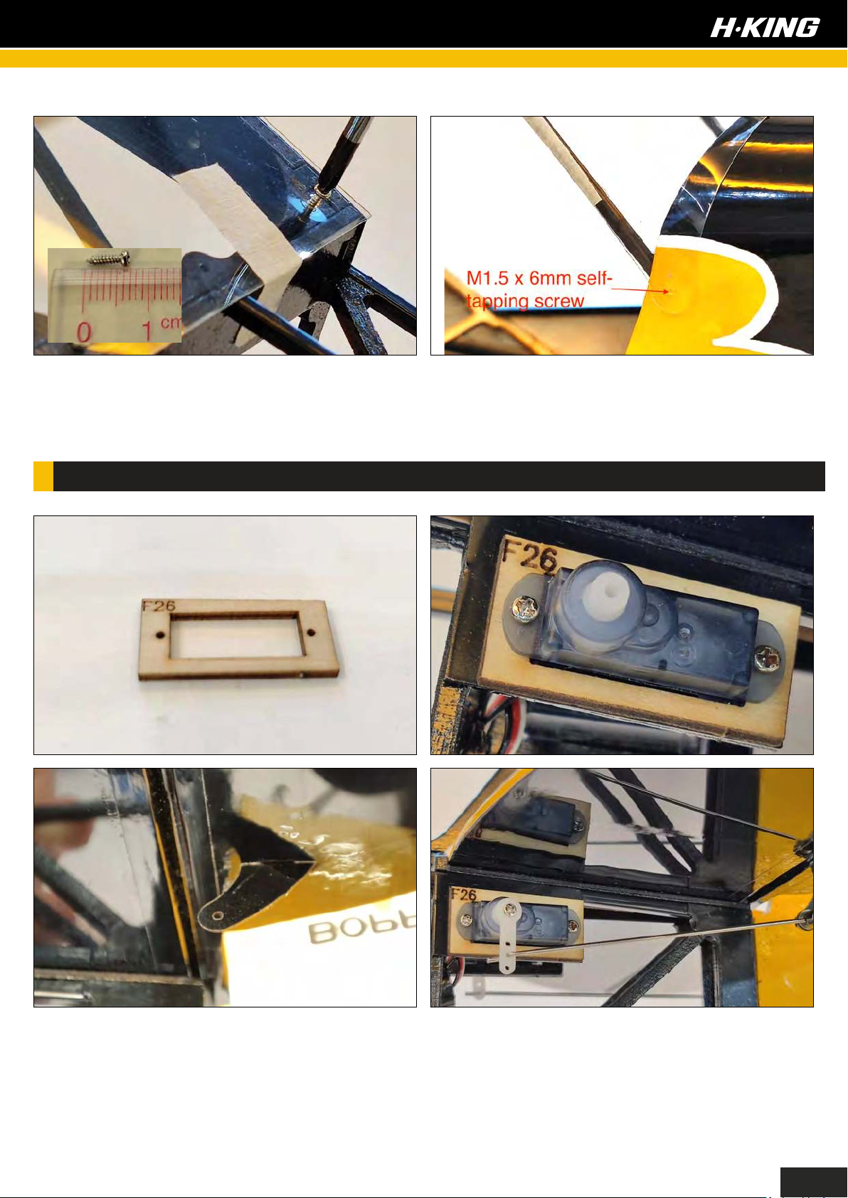
Then tape the other end to the rear part of the wing saddle. Once you are satisfied with the overall
fit and placement of the PVC windshield, secure it in place using the supplied M1.5x6 mm
self-tapping screws.
ELEVATOR AND RUDDER SERVO INSTALLATION:
Before installing the elevator servo, feed the servo lead through the plastic tube from the tail
servo mount at the rear of the fuselage to the main radio compartment. A couple of standard
servo extension leads or a single longer one are required for this setup. Using a medium CA glue,
glue the supplied control surface horn to the elevator. This kit includes a couple of servo
mounting spacers (F26), these are required if using the larger 5 or 6g servos which need a bit
more room in the tight servo compartment at the tail. However, if you are using smaller size
servos, then these spacers should not be required.
9
Page 12
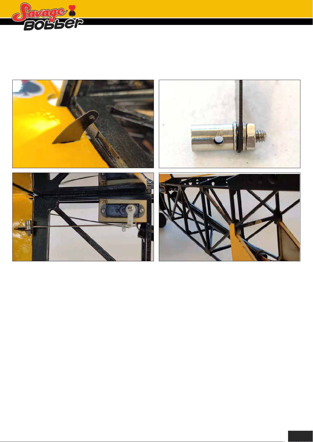
Connect the pushrod to the servo control horn and connect the pushrod stopper as shown. Get a
piece of masking tape to hold the control surface straight and level, then tighten the grub screw on
the stopper with a hex key. Apply a small spot of thread lock glue where necessary. Trim off the
excess pushrod length with a
set of wire cutters.
Repeat the above steps for the rudder servo pushrod linkage installation.
10
Page 13
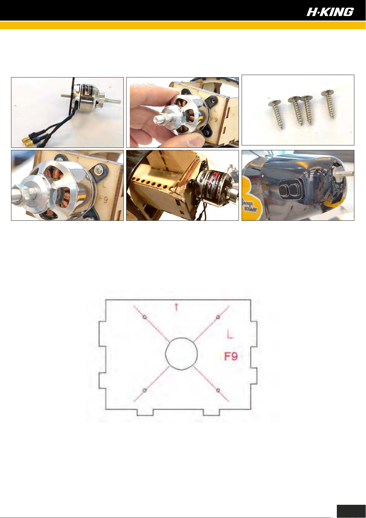
First of all, install the X mount to the motor. Then position it to achieve the correct motor offset,
thrust line as indicated by the red arrow on former F9. Secure the motor in place by using the
supplied M3 x10 mm self-tapping screws.
The firewall on the Savage Bobber has a built-in 3 degrees of right thrust. This is a good
starting point for the recommended propeller size. If you feel you need a little more right thrust
angle, you may add additional washers top and bottom of the X mount on the left hand side to
achieve even better straight and level flight flying trim.
Finally, trial fit the cowling onto the fuselage and adjust accordingly to get the proper fit. To make
the adjustment and set-up easier we recommend that you use some masking tape to hold it in
place. Set it so that no rubbing occurs between the prop adapter and the front of the cowling.
If you find that the cowl is raised at the front and the firewall is pushing against the inside of the
cowl, gently sand the top corners of the firewall until you have a satisfactory fit. We suggest you
apply a thin layer of medium CA glue to the seam inside the motor box and the sanded area for
added strength. Once you are satisfied with the fit, secure the cowling onto the fuselage by using
the supplied M1.5 x 6 mm self-tapping screws.
11
Page 14
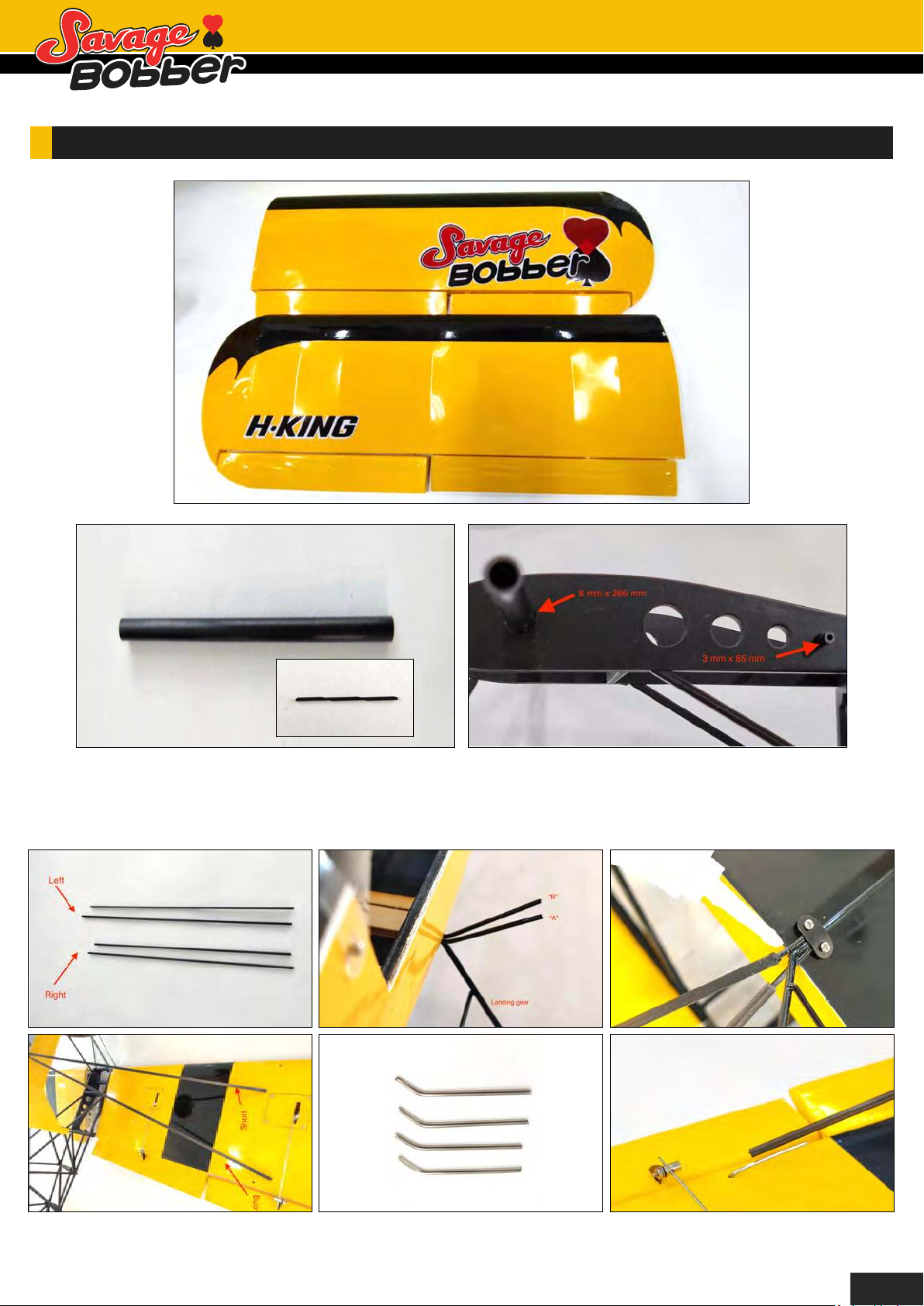
MAIN WING INSTALLATION:
Insert the supplied 8 mm x 265 mm and 3 mm x 85 mm carbon fiber wing joiner onto the fuselage
wing saddle as shown. Install the left wing onto the fuselage.
12
Page 15
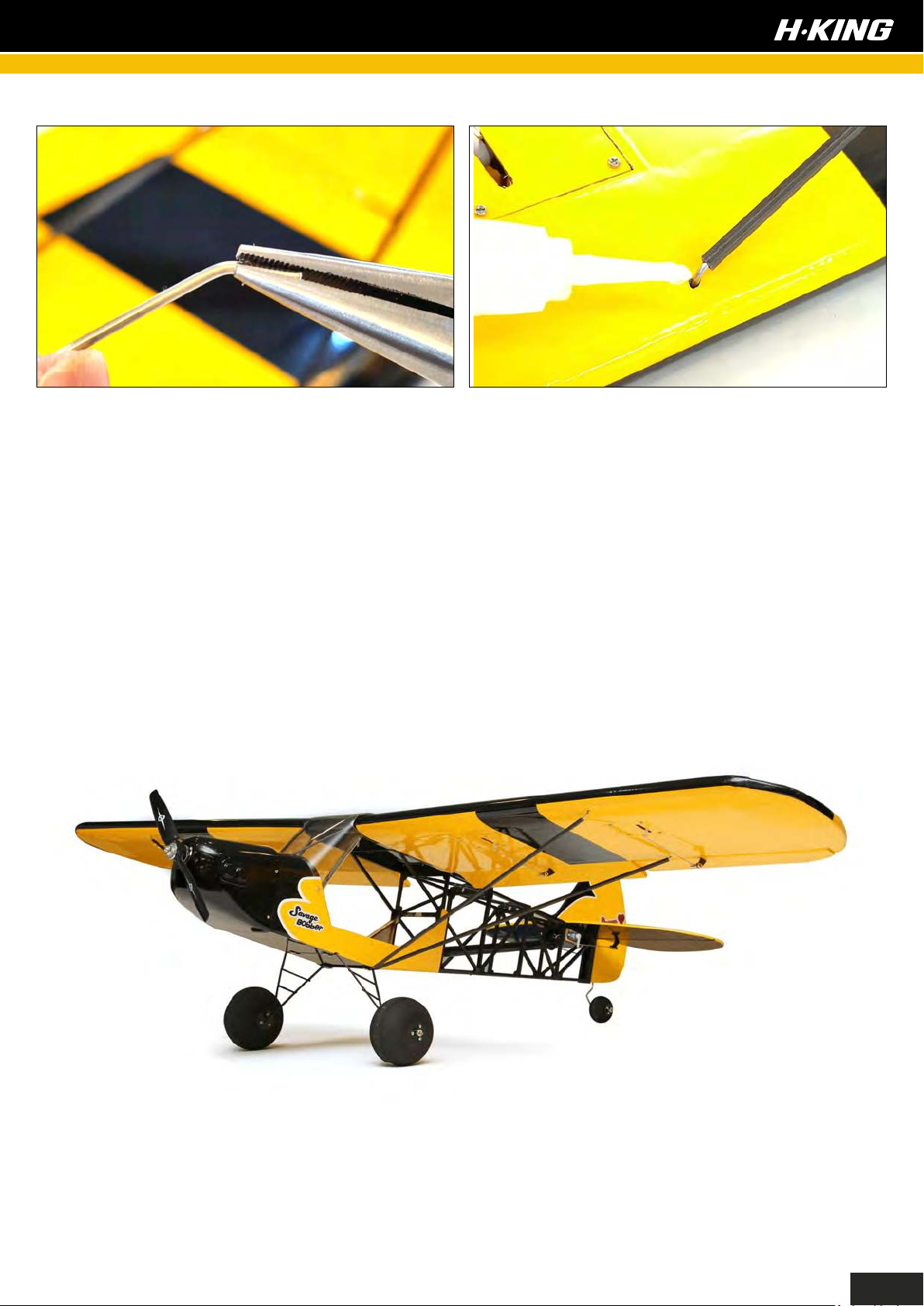
We have supplied a set of carbon fiber wing struts. Identify the longer one for the rear wing strut
and the shorter one for the front. Two additional metal fittings are also required for the installation.
Install the carbon fiber wing strut (rear) to “A” and insert the metal fitting onto the other end. Then
insert it into the pre-drilled hole on the underside of the wing, ensure the metal fitting is fully
inserted. You may have to use a pair of pliers to make some adjustments to achieve a proper fit.
Once you are happy with the setup, you may apply a spot of glue to hold it in place.
Repeat the above steps for the right wing.
COMPLETE
13
Page 16
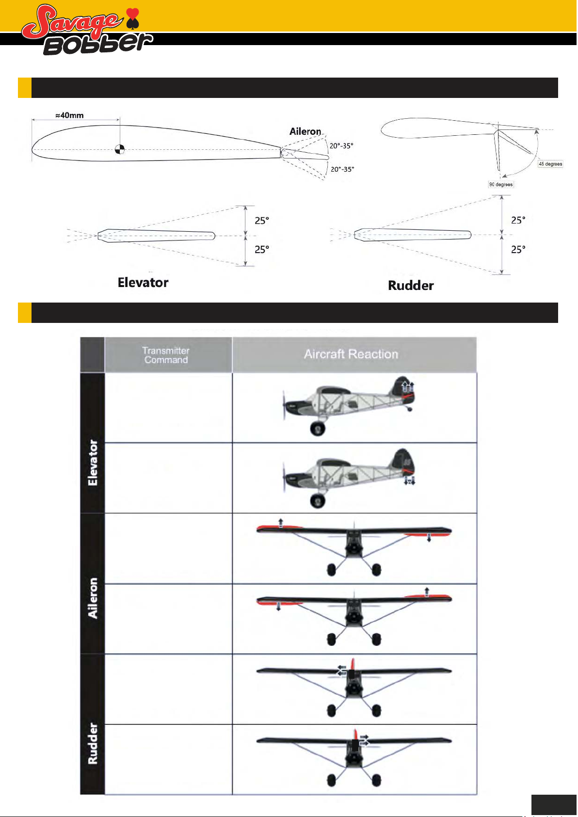
C OF G AND CONTROL SURFACE THROW SETTING INFORMATION:
CONTROL DIRECTIONS TESTS:
Stick backward
Stick forward
Stick right
Stick left
Stick right
View from the nose.
View from the nose.
Stick left
View from the nose.
View from the nose.
14
Page 17

MODEL FLYING PRECAUTIONS:
YOUR NIGHT TUNDRA COMES WITH SEVERAL FEATURES
• Select your flying area carefully. Always choose an open space that is clear and not obstructed by
trees, poles, pylons, and buildings etc. Also ensure you are away from people and crowded areas.
Avoid flying in areas with roads, near water, or within close proximity to full size air traffic.
• Do not fly this model in poor weather, for example: high winds, low visibility, inclement temperatures,
and rain and storms are also to be avoided.
• Never attempt to catch the model whilst it is in flight, even a slow moving model can cause harm to
yourself and risks damage to the model.
• This model is not recommended for children under the age of 14 years old. All children no matter
what age, should be supervised by a capable and responsible adult when operating this model.
• Always unplug your model battery when not in use, never leave the battery installed in the model.
• Please remember to keep clear of the propellers at all times when your flight battery is connected.
• Before flying, always turn ON your transmitter first, then plug your flight battery into the model.
• After flying, always unplug your battery first in the model and then turn OFF your transmitter.
• Exercise caution when charging your batteries, and follow in full your battery manufacturers safety
guideline when doing so.
PRE-FLIGHT CHECKS:
Always range check your model before any flight (especially when flying a new model for the first
time). Follow your radio manufacturers guidelines for performing this check.
Check all screw bolts and mounting points are firmly secure, including control horns and
clevises.
Only fly with fully charged batteries (both in your radio and model). Failure to do so could result
in loss of control, damage to the model and/or persons/property around you. Check your
batteries are fully charged.
With the model powered up ( ransmitter on first, then receiver/model) check that all surfaces are
free from damage/obstructions, moving in the correct directions and freely with stick input
Inspect the model and prop for any damage that may have occurred during transit and listen for
any unusual sounds from the electronics when powered up. If in doubt, do not fly.
With the model held securely and the prop free of obstructions, increase the throttle just slightly
to confirm the rotation of the prop is correct. The model should want to pull straight forward with
throttle.
.
If this is your first flight with the model double check the C/G is at the correct position. If not adjust
battery position inside model accordingly.
If you are an inexperienced model pilot seek the help and assistance of an experienced pilot to
perform these final checks and to test fly the model for you.
15
Page 18
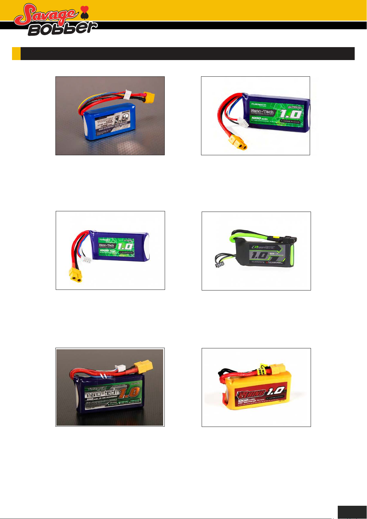
RECOMMEND BATTERY:
Turnigy 1000mAh 3S 30C Lipo
Pack
SKU: T1000.3S.30
Turnigy Nano-Tech Plus
1000mAh 3S 70C Lipo Pack w/
XT60
SKU: 9210000261-0
Turnigy Nano-Tech 1000mAh
3S 40C Lipo Pack w/XT60
SKU: 9210000274-0
Turnigy Graphene Panther
1000mAh 3S 75C Battery Pack
SKU: 9067000361-0
Turnigy nano-tech 1000mah 3S
25~50C Lipo Pack
SKU: N1000.3S.25
Rhino 1000mAh 3S 25C Lipo
Battery Pack w/XT60
SKU: 9952000010-0
16
Page 19

UK REP
UK REP
EC REP
EC REP
APEX CE SPECIALISTS LIMITED
APEX CE SPECIALISTS LIMITED
M1 4HT, UK
M1 4HT, UK
APEX CE SPECIALISTS LIMITED
APEX CE SPECIALISTS LIMITED
 Loading...