

Page 1
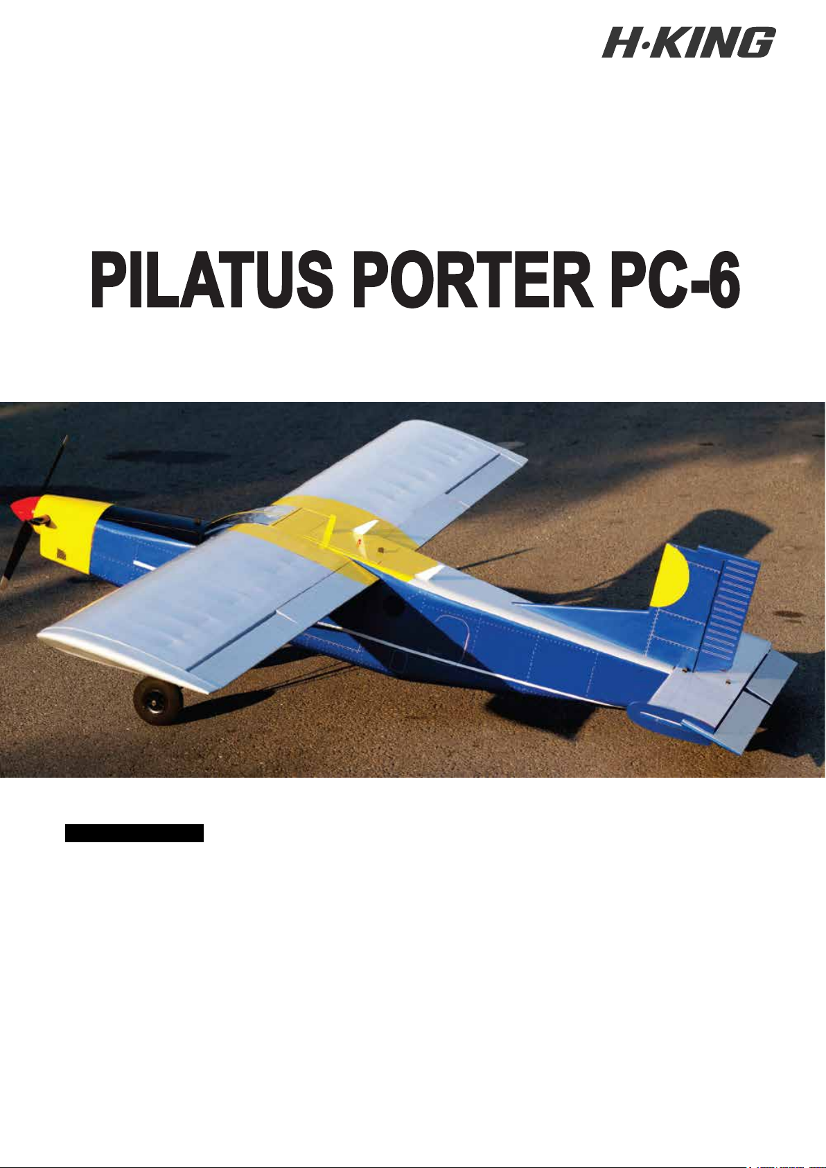
RADIO CONTROL MODEL
BUILDING INSTRUCTIONS
EP/GP Balsa 2150mm ARF
SPECIFICATIONS
Wingspan:
Length:
Flying weight:
Gas Engine:
Nitro Engine:
Motor:
Radio:
WARNING! This radio controlled model is NOT a toy. If modified or flown carelessly it could go out of controll and
cause serious human injury or property damage. Before flying your airplane, ensure the air field is spacious enough.
Always fly it outdoors in safe areas and seek professional advice if you are unexperienced.
DISCLAIMER:
All product names, logos, brands, trademarks and registered trademarks are property of their respective owners. Use of these names, trademarks and brands does
not imply endorsement.
6 Channels / 7-8 servos
95 2T / 1.20 4T
SK3-4240-740Kv
2150mm
1600mm
4.6-4.9Kg
20cc 2T
Page 2
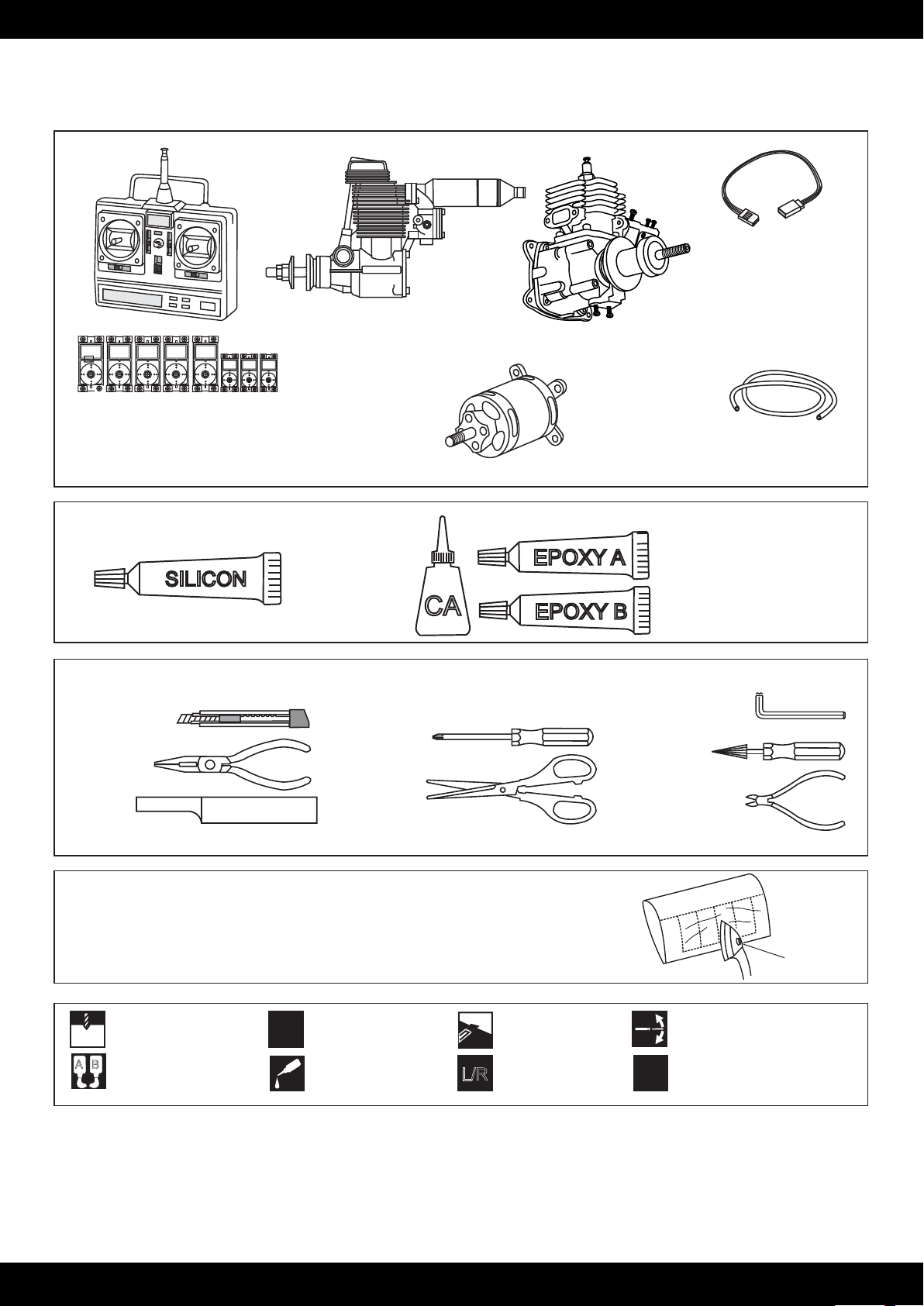
REQUIRED FOR OPERATION (Purchase separately)
Extension for aileron,
Flap , Elevator servo.
Glow 1.20 4T Engine
Gas Engine: 20cc
6 channel radio for airplane
with 5 standard servos and 3 mini servos
Flapx2 standard servo - Aileronx2 standard servo
Rudderx1 standard servo - Elevatorx2 mini servo
Motorx1 mini servo
GLUE
(Purchase separately)
SILICON
Cyanoacrylate
Glue
Silicon sealer
TOLLS REQUIRED
(Purchase separately)
Hobby knife
Needle nose Pliers
Sander
.........................................................
.........................................................
.........................................................
.........................................................
.........................................................
.........................................................
.........................................................
.........................................................
.........................................................
.........................................................
.........................................................
Masking tape - Straight Edged Ruler - Pen or pencil - Drill and Assorted Drill Bits
CA
Phillip screw driver
Scissors
SK3-4240-740Kv
Brushless Motor
EPOXY A
EPOXY B
Nylon tube
Epoxy Glue (5 minute type)
Epoxy Glue (30 minute type)
Hex Wrench
Awl
Wire Cutters
If exposed to direct sunlight and/or heat, wrinkels can appear. Storing the
model in a cool place will let the wrinkles disappear. Otherwise, remove
wrinkles in covering film with a hair dryer, starting with
low temperature. You can fix the corners by using a hot iron.
Drill holes using the stated
size of drill
1.5mm
(in this case 1.5 mm Ø)
A
B
Use epoxy glue
Take particular care here
!
Apply cyano glue
CA
Hatched-in areas:
remove covering
film carefully
Assemble left and right
L/R
sides the same way.
CONVERSION TABLE
1.0mm = 3/64”
1.5mm = 1/16”
2.0mm = 5/64”
2.5mm = 3/32”
3.0mm = 1/8”
4.0mm = 5/32”
5.0mm = 13/64”
6.0mm = 15/64”
10mm = 13/32”
1
Check during assembly that these
parts move freely, without binding
Not included.
These parts must be
X
12mm = 15/32”
15mm = 19/32”
20mm = 51/64”
Low setting
purchased separately
25mm = 1”
30mm = 1-3/16”
45mm = 1-51/64”
Page 3
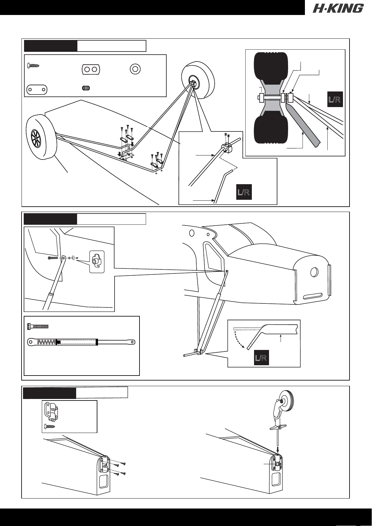
PC-6 Porter
3x12mm screw
...................8
Nylon strap
............4
1- Landing gear
Stopper (metal)
...........2
3mm set screw
..............4
BOTTOM - VIEW
5.5mm Collar
...........4
Collar
5.5mm Collar
Stellring
Stopper (metal)
5mm landing
gear
L/R
Caution: All holes on the bottom of the
fuselage are pre-drilled at factory
PC-6 Porter
3x15mm
3x15mm screw
.........................................2
Spring...............................................2
2- Landing gear
All blindnuts are
installed at factory
5mm landing gear
(front)
5mm landing gear
(rear)
L/R
Aluminum tube
5mm Main landing gear
Main landing gear (5mm).................2
Landing gear (5mm).........................1
PC-6 Porter
Tail gear mount...1
3x12mm screw......4
3- Tail gear
3x12mm screw
3A
Aluminum tube
L/R
Two holes on the left and the right side of the fuselage are pre-drilled at factory
OM - VIEW / Unteransicht
BOTT
3mm collar
3B
2
Page 4
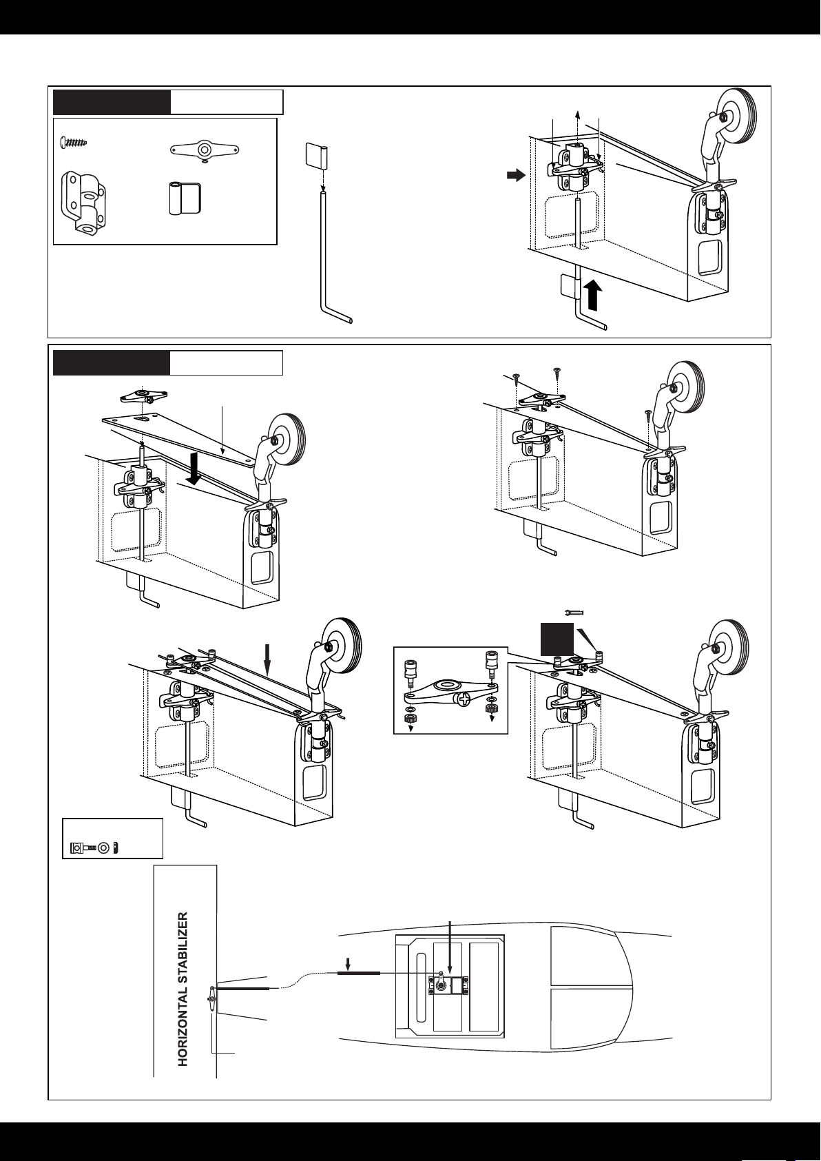
PC-6 Porter
3x12mm screw
...........4
Tail gear mount
...2
4- Tail gear
Tail gear control arm
...2
..........1
Tail gear control horn B
Note: Slide the tail gear
push rod in to he hole of
the tail gear control horn
B first.
2mm tail gear torque rod
Tail gear push rod
PC-6 Porter
5- Tail gear
Hatch (plywood)
ail wheel push rod
T
5A
4A
BOTTOM - VIEW
BOTTOM - VIEW
4B
5B
Connector
5C5D
........2
Rudder servo
Rudder push rod
Rudder arm
FUSELAGE TOP-VIEW
3
Page 5
PC-6 Porter
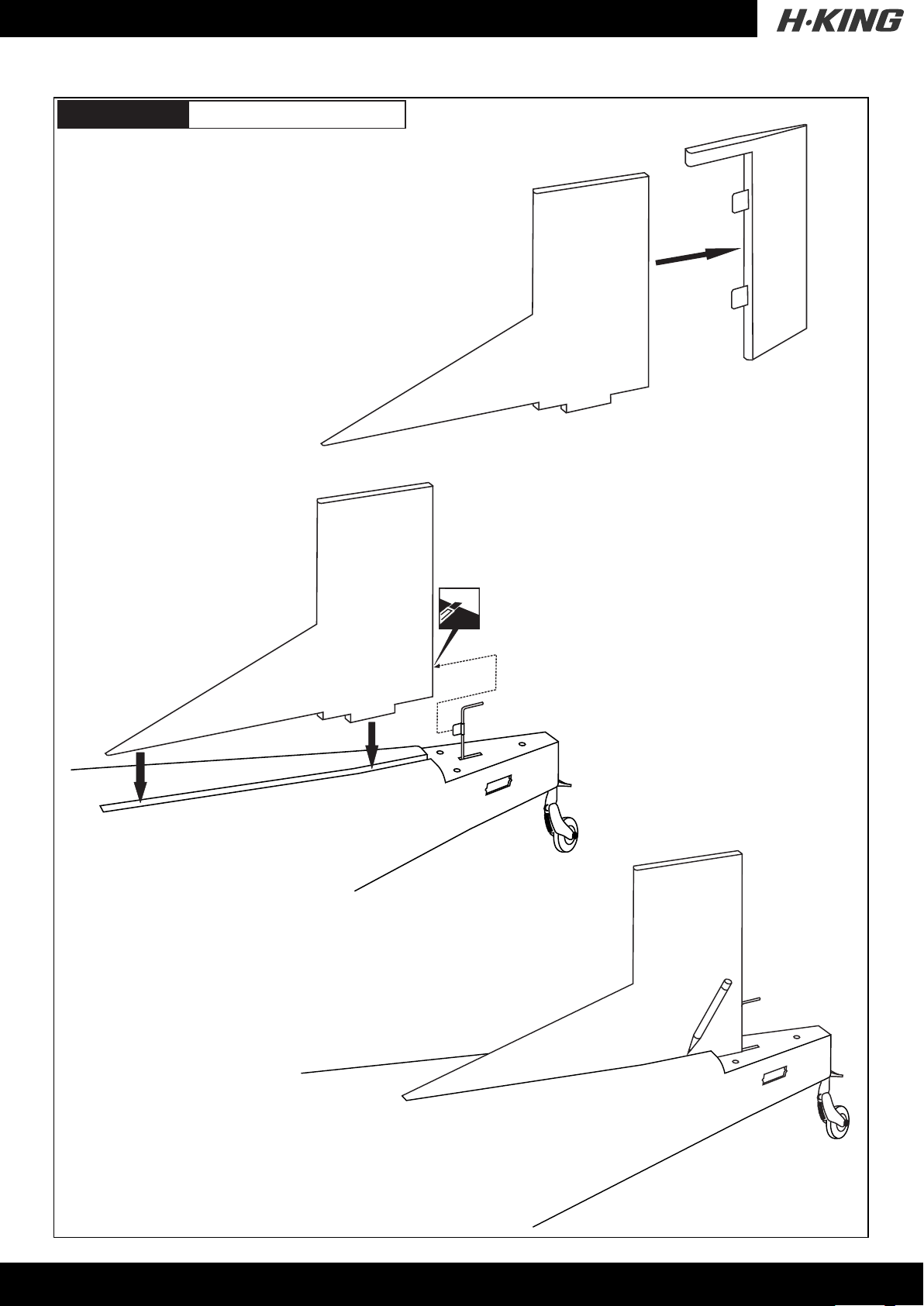
6- Vertical stabilizer
Full the rudder out of the Vertical stabilizer.
Cut 7/8” (22mm) long slots along the hinge line in the
trailing edge of the vertical stabilizer for the rudder
torque rod bearing. Position of the slot on the side of
the vertical stabilizer, 2”(50mm) from the bottom (6A)
TOP VIEW
Test-fit the rudder torque rods into the slot.
NOTE: You may need to open up the slots so that
the torque rod bearing are not too difficult to push in
6A
Do not glue as this time
When you are satisfied with the alignment,
use a pencil to trace around the left and
right of the stabilizer where it meets the
fuselage(6B)
6B
4
Page 6
PC-6 Porter
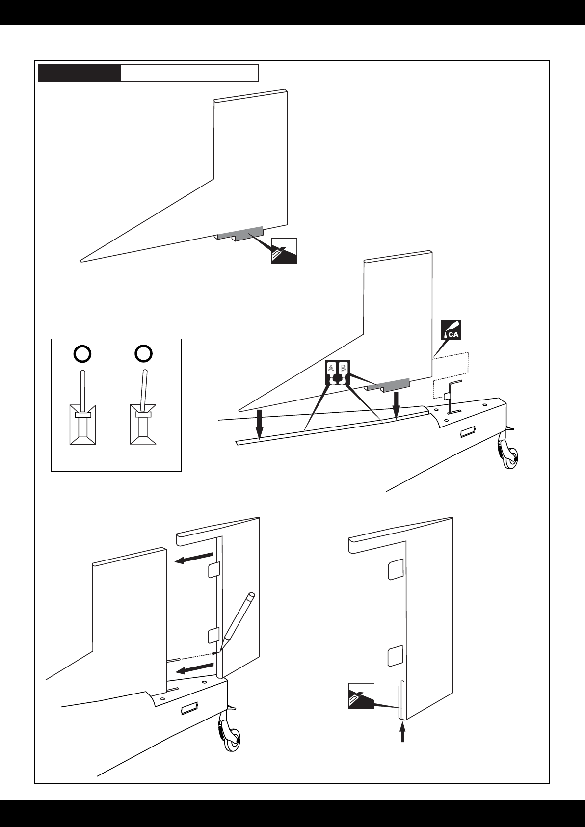
7- Vertical stabilizer
6C
Remove the vertical stabilizer from the fuselage.
Using the sharp hobby knife, carefully cut away the
covering inside the lines which were marked above(6C)
* WARNING: When removing any covering from the airframe,
please ensure that you secure the cut edge with CA or similar
cement. This will ensure the covering remain tight.
Cut away only
the covering
both side
Secure the torque rod
bearing using Thin CA
Thin CA glue
X
FUSELAGE
REAR VIEW
Mark the rudder where the end of rudder torque rod
meet the rudder.
FUSELAGE
REAR VIEW
! Securely glue together If coming off during
fly, you lose control of your air plane.
A
B
6D
Cut away the covering material
from over the precut rudder
torque rod mounting slot in rudder.
55
Page 7
PC-6 Porter
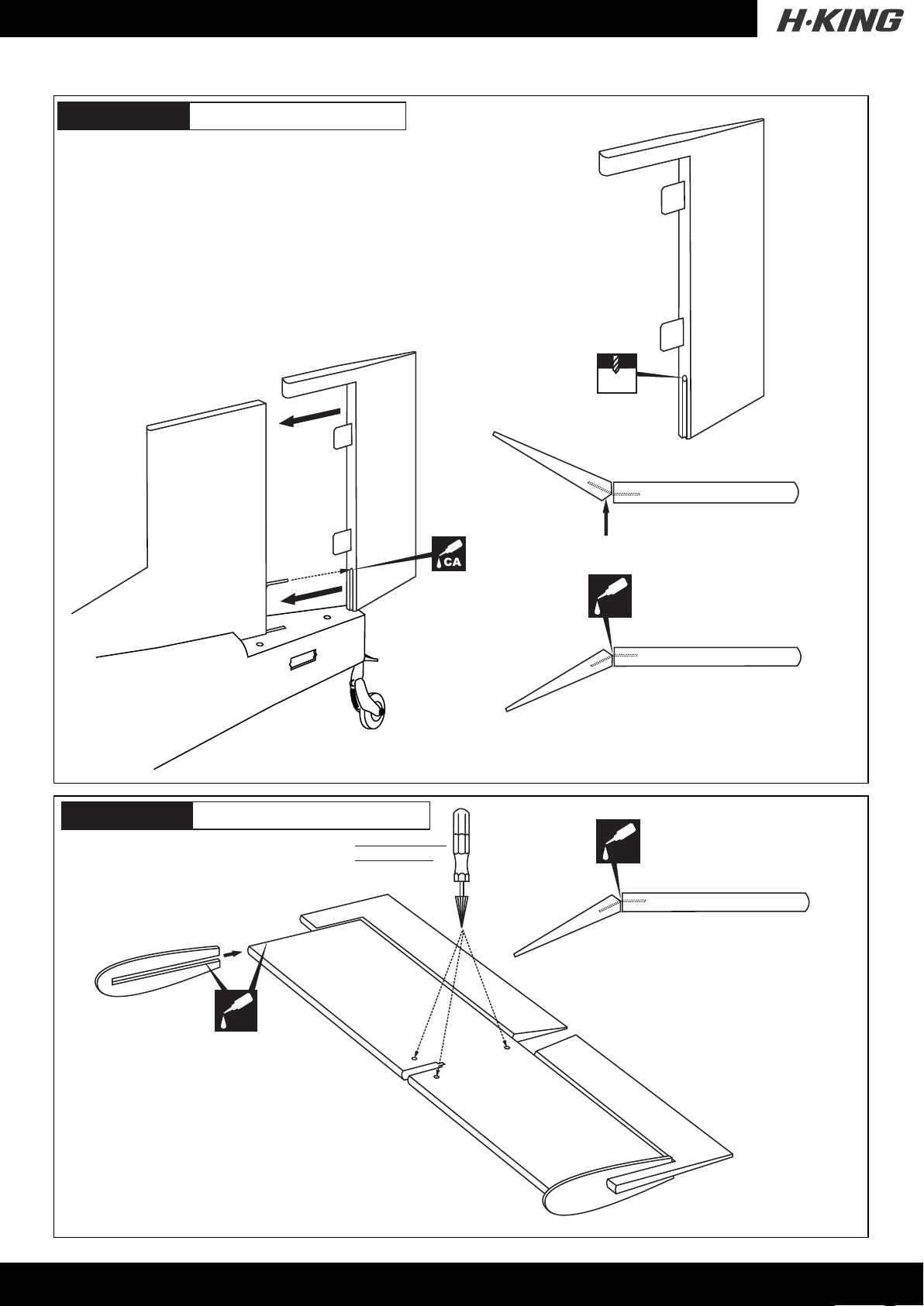
8- Vertical stabilizer
Drill a 5/64”(2mm) diameter hole in torque
rod mounting slot, marking sure that you drill
the hole perpendicular to the leading edge of
the rudder.
2mm
TOP-VIEW
VERTIAL STABILIZER
Apply a thin layer of petroleum jelly
PC-6 Porter
9- Horizontal stabilizer
Cut away only
the covering
CA
Apply thin CA glue
on the left (right) of
CA
the hinge.
VERTICAL STABILIZER
! Securely glue together. If coming off
during fly, you lose control of your
air plane.
Apply thin CA glue
on the top (bottom) of
CA
the hinge.
HORIZONTAL STABILIZER
! Securely glue together. If coming off
during fly, you lose control of your
air plane.
6
Page 8
PC-6 Porter
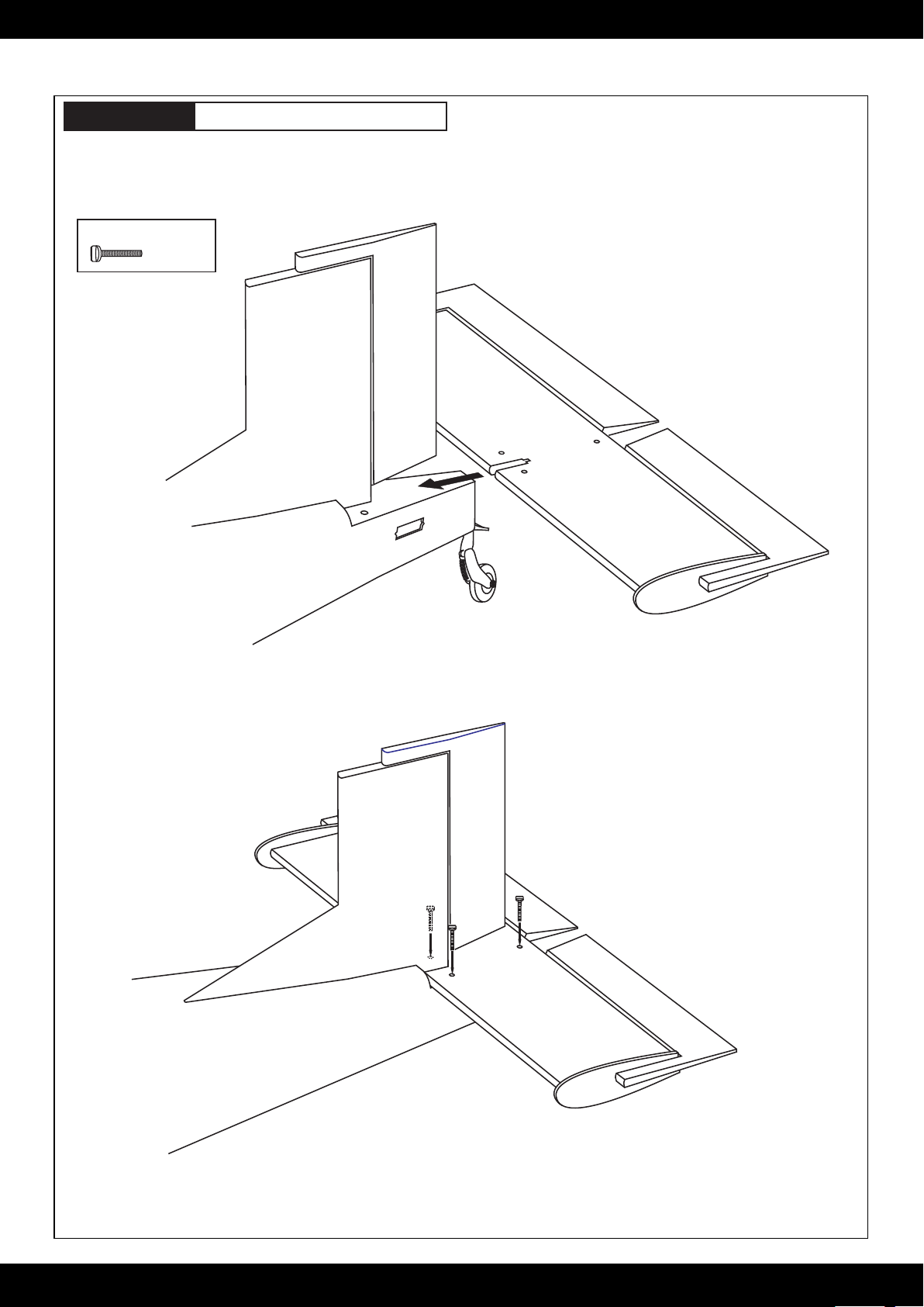
30x4mm nylon bolt
............3
10- Horizontal stabilizer
7B
7
Page 9
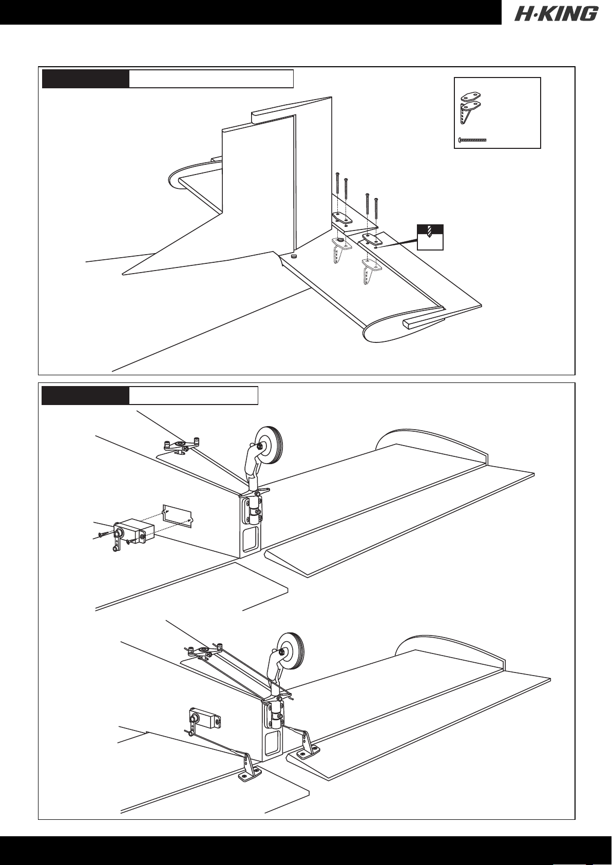
PC-6 Porter
11- Horizontal stabilizer
Control horn
......................2
2x30mm screw
................4
2mm
PC-6 Porter
9A
12- Elevator servo
BOTTOM - VIEW
9B
8
Page 10
PC-6 Porter
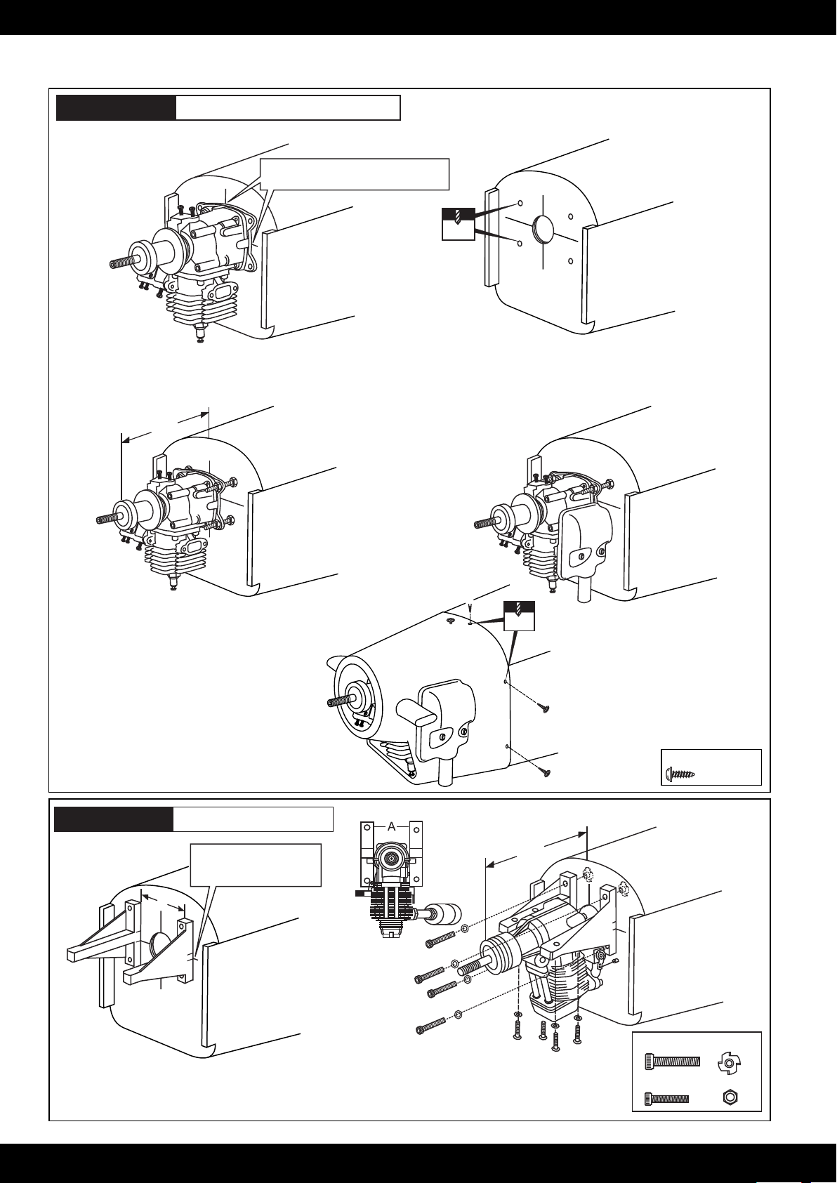
13- Gas Engine & Cowl
! Align the center mark on the engine
with the mark on the fire-wall.
5mm
10A
Using a pencil or felt tipped pen, mark the fire wall
where the four holes are to be drilled (10A).
123 - 125mm
10C
Reposition the engine on to the fire-wall so
the distance from the prop hub to the fire-wall is
4.8 - 4.9”(123 - 125mm) (10C).
10B
Remove the engine mount and drill a 13/64”(5mm) hole
through the fire-wall at each of the four marks marked (10B).
10D
2mm
10E
PC-6 Porter
14- Glow Engine
! Align the mark on both
mounts with the mark on
the fuselage
A
Using a pencil or felt tipped pen, mark the fire wall where the four holes are to be drilled
Remove the engine mount and drill a 5mm hole through the fire-wall at each of the four marks marked.
Attach the four blind-nut to the fire-wall as show
FRONT-VIEW
123 - 125mm
3x12mm screw
...........5
4x25mm...............4
3x20mm...............4
9
Page 11
PC-6 Porter
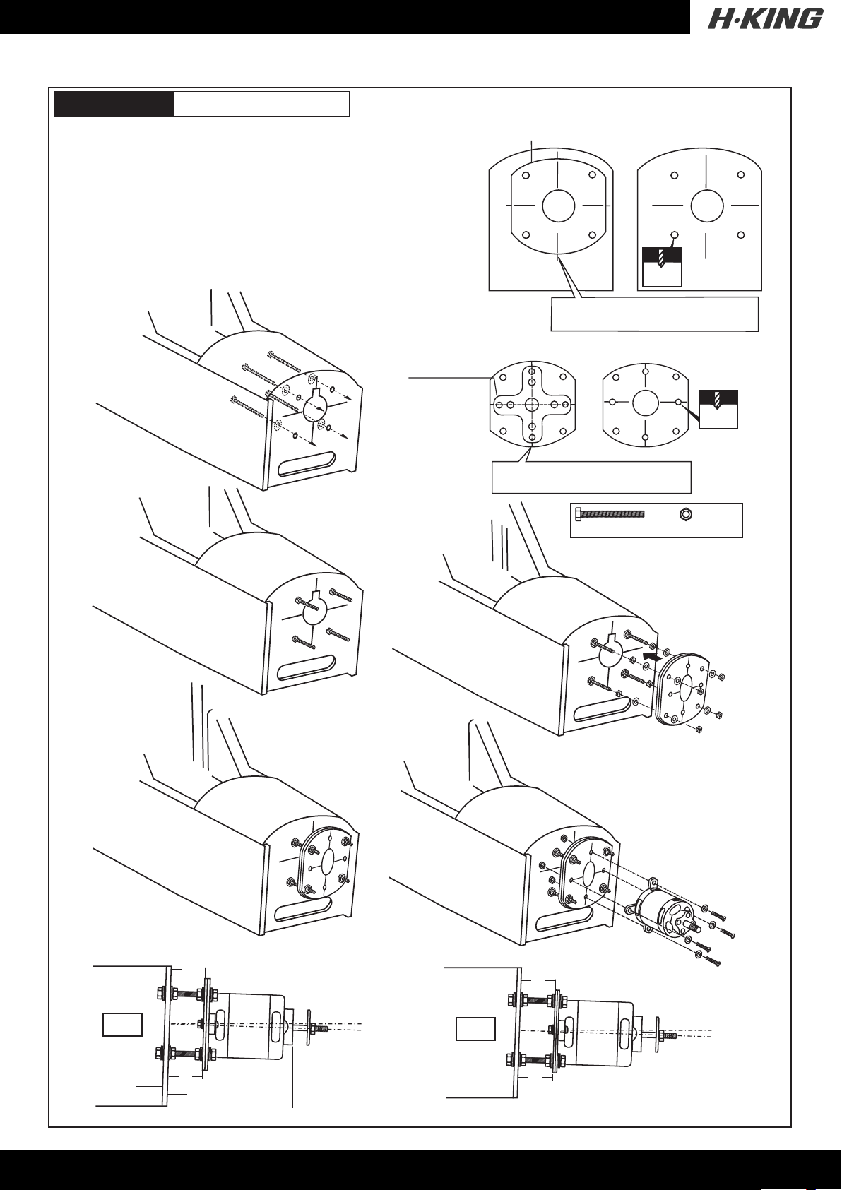
- Using a plywood motor mounting plate as a template, mark the fire wall
where the four holes are to be drilled (12A).
- Remove the plywood motor mounting plate and drill a 13/64”(5mm) hole
through the fire-wall at each of the four marks marked (12B).
- Using a aluminum motor mounting plate as a template, mark the
plywood motor mounting plate where the four holes are to be drilled (12C).
- Remove the aluminum motor mounting plate and drill a 1/8”(3mm) hole
through the plywood at each of the four marks marked (12D).
15- Electric motor
Montagekreuz aus
Alu (nicht enthalten)
Aluminum motor
mounting plate
Plywood motor mounting plate
Sperrholztrager Platten
12A
! Align with the marks
An den Markierungen ausrichten
FRONT-VIEW
Vorderansicht
5mm
12B
1/8”
3mm
12E
12F
12C
! Align with the marks
An den Markierungen ausrichten
5x70mm.......4
12G
12D
4mm.......x12
B=B’
Firewall
Motorspant
12H
B
B’
123~125mm
SIDE-VIEW
10
12I
A=A’
A
TOP-VIEW
A’
Note the side thrust for motor!
Page 12
PC-6 Porter
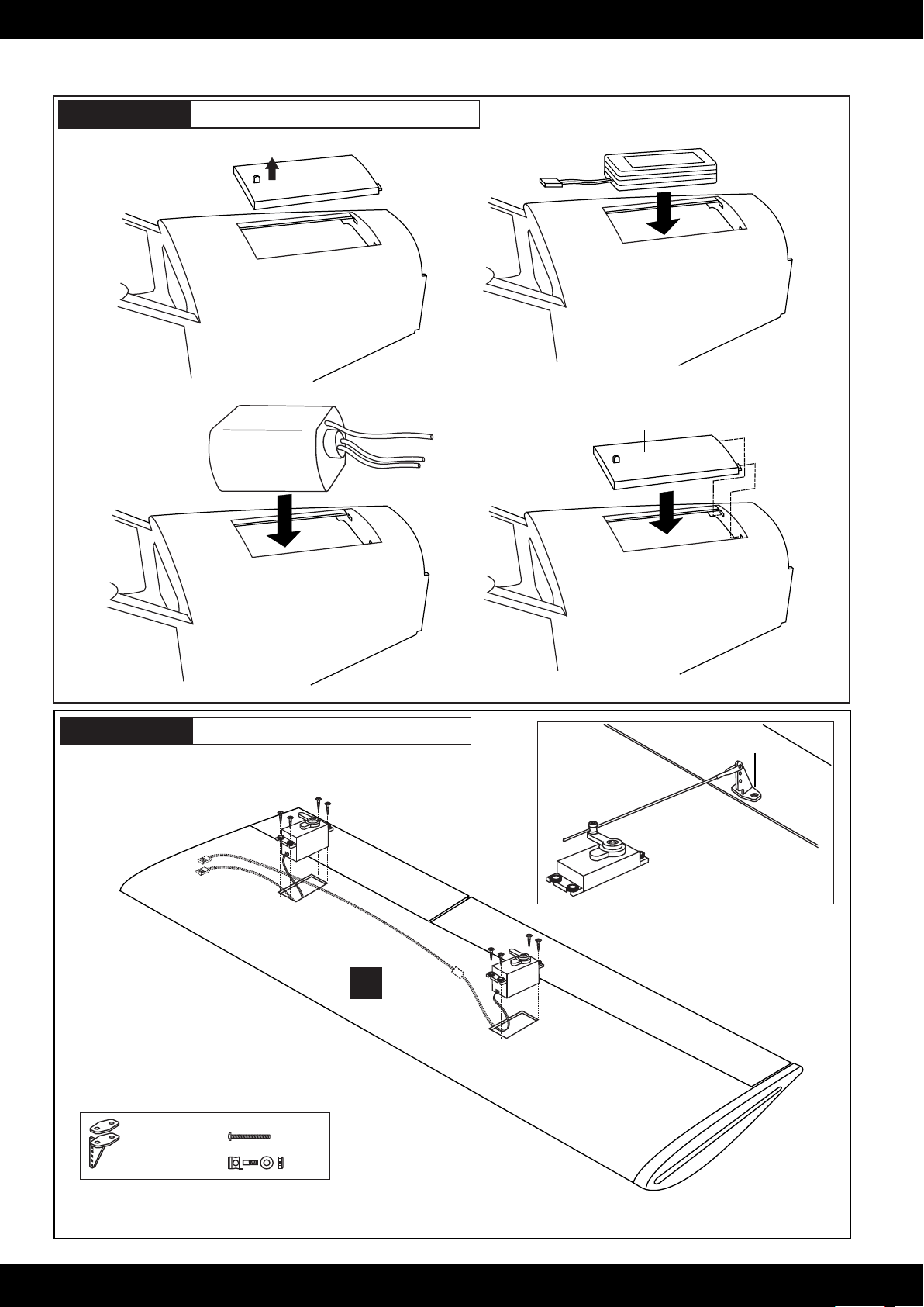
Full the magnetic battery
hatch out of the fuselage.
16- Fuel tank / Lipo. Battery
Put the Li-Po battery
in place.
PC-6 Porter
13A
Put the fuel tank
in place.
13C
17- Aileron and flap servo
13B
Magnetic battery hatch.
13D
Aileron control horn
Control horn
...................2
15A
2x30mm screw
X
BOTTOM - VIEW
..........4
......2
Aileron servo
extension
cord
15B
11
Page 13
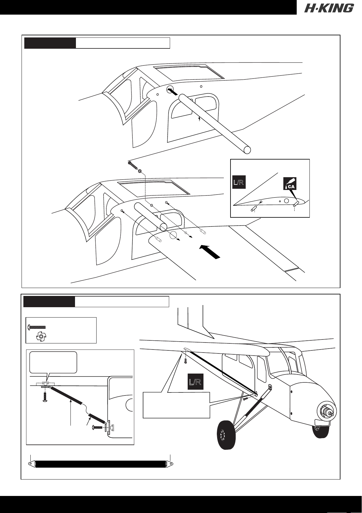
PC-6 Porter
18- Installing the wing
Aluminum tube
14A
14B
L/R
PC-6 Porter
3x15mm screw / Schraube
............................2
............................2
The blind-nut on the
bottom of the wing
installed at factory
19- Installing the wing
Wing
14C
L/R
Wooden dowel
Wooden dowel
3x15mm
sscrew
Wing brace
To the bottom of the wing
Wing brace ( right - left)
The holes on the bottom
of the wings and side of
the fuselage are pre-drilled
at factory
3x15mm
sscrew
To the side of the fuselage
12
Page 14
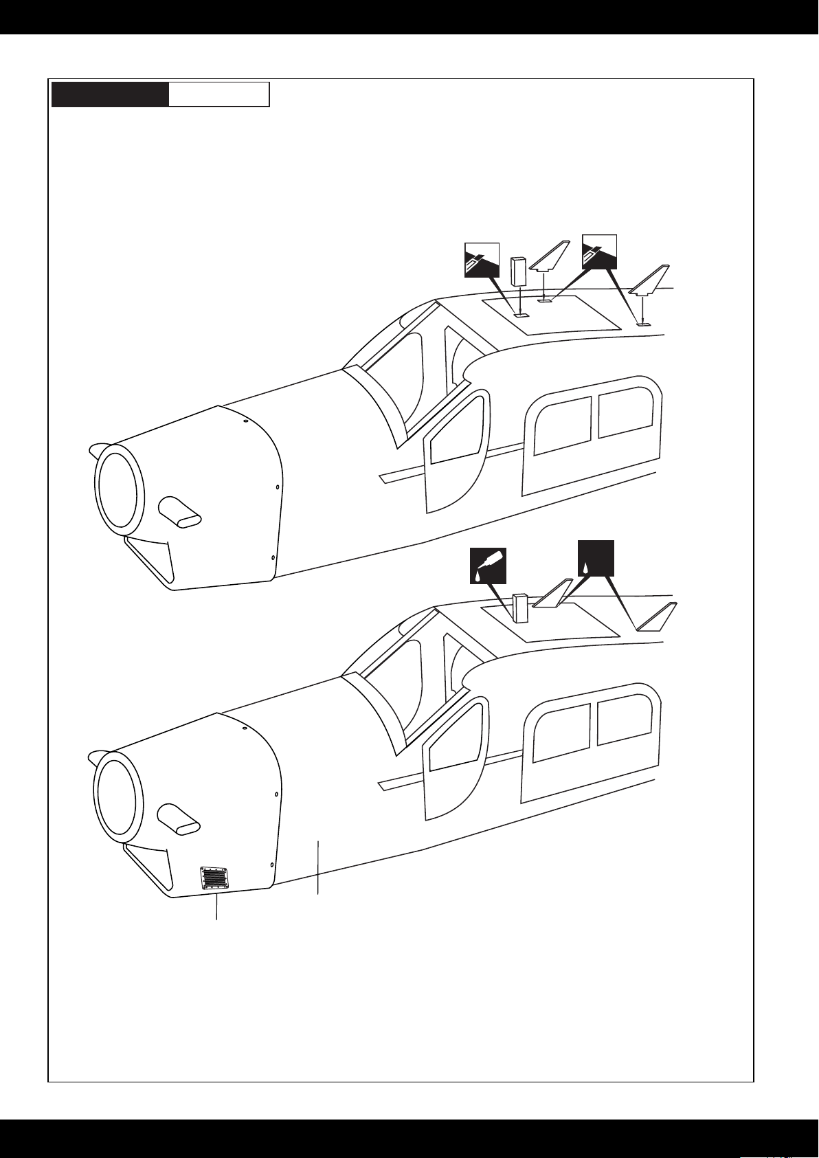
PC-6 Porter
20- Decor
IMPORTANT:
Please do not clean your model with pure alcohol,
only use liquid soap with water or use glass cleaner
to clean on surface of your model to keep the colour
not fade.
Cut through the balsa Cut through the balsa
Sticker
Sticker
CA
CA
13
Page 15
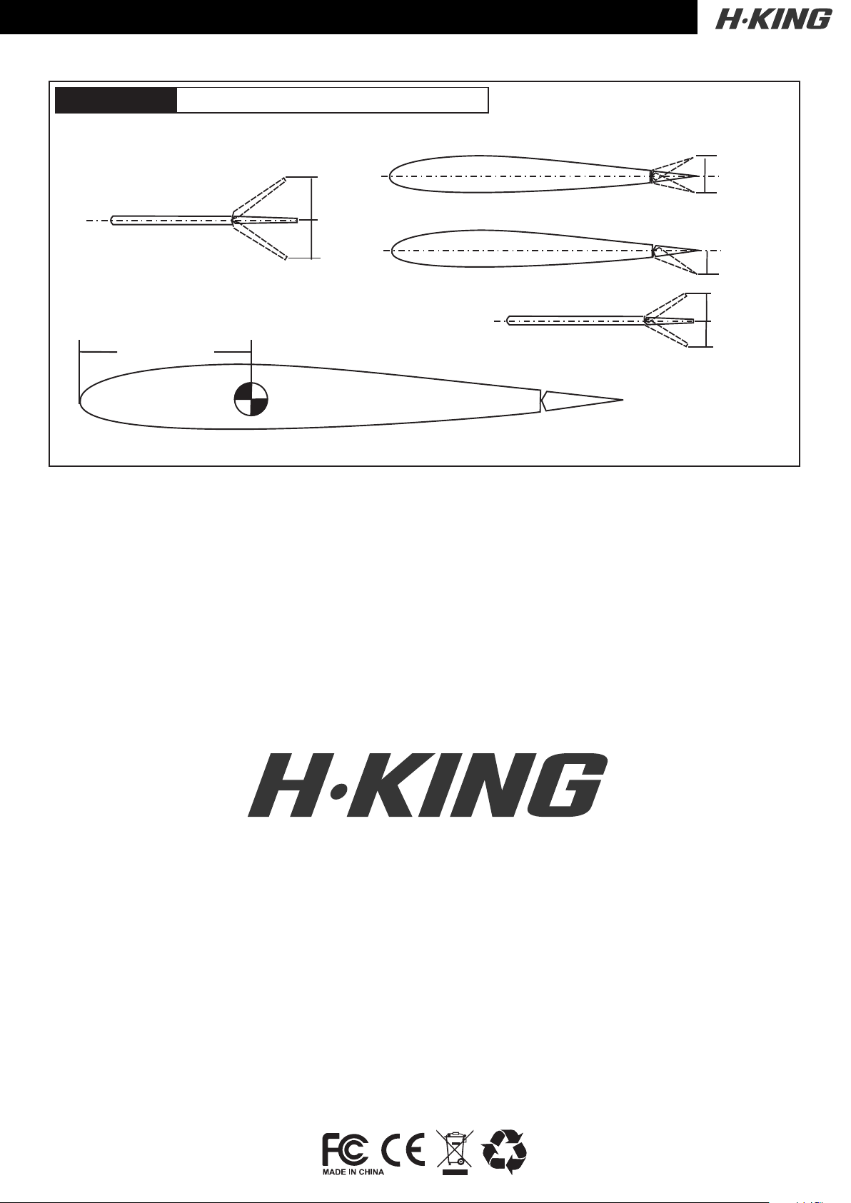
PC-6 Porter
Rudder
21- Balance and control surface
Aileron
15mm
15mm
30mm
Flap
30mm
20mm
Do not try to fly an out-of balance model!
75 ~ 80mm
Elevator
15mm
15mm
 Loading...