

Page 1
INSTRUCTION MANUAL
Please read this manual carefully before operating this plane.
Page 2

CONTENTS
Introduction 1
Features 1
Specifications 1
Required 1
Warnings and Safety notes 2
Contents 3
General assembly 4 - 16
Radio setup 17 - 18
Attaching the Parawing 19 - 20
Safety instructions 21
Flying the Paramotor V2 22 - 23
Recommended accessories 24 - 26
Spare Parts 27
Page 3
INTRODUCTION
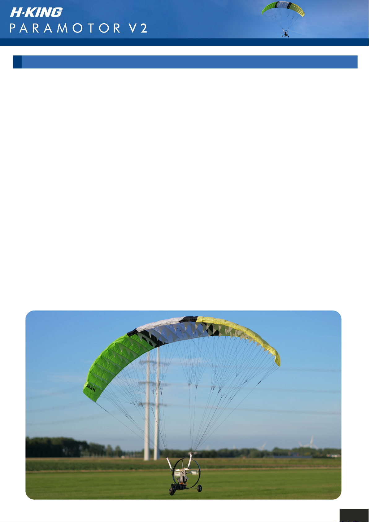
Following on from the incredible success of the first H-King Paramotor comes this V2. This version
sports a new, much more efficient, stable, larger-span parafoil wing in a vibrant color scheme. This
makes it so much easier to launch and fly and adds much more stability when flying than the
previous version offered. This improved stability and control will allow you to perform controlled
touch and goes, and with practice (and a willing helper) it will even do rolling take-offs. Another
improvement is the lines that attach the gondola to the parafoil, these are stronger, and much
smoother, so are less likely to bind to each other when launching. Next on the list of new features
are clear servo arms for added realism, a super bright LED light bar, and a white prop. This light
bar illuminates the underneath of the sail and reflects off the white prop allowing you to have even
more fun with your paramotor by enabling you to carry on flying into the twilight zone.
The V2 still retains many of the characteristics of the original version, including the ability to perform
loops and rolls with ease after a little practice. The large area high performance 2400mm parafoil
wing opens quickly for easy launching and due to its design it will retain its shape even in severe
turbulence. The single-skin durable wing is made from 100% ripstop fabric and the new, stronger
nylon chords are rigged and ready to attach to the durable aluminum gondola.
Just like the original version, there is a high level of prefabrication so assembly time is kept to a
minimum, and as it is supplied in a Plug-N-Fly format all you will require to get flying is your
transmitter, receiver, LiPo battery, and charger. The Paramotor V2 is fitted with a powerful
3530-1400KV brushless motor swinging a 10x4.7 propellor, has a 50 amp electronic speed
controller with 5A BEC, and 2 powerful 15kg high torque metal geared servos. A 3S LiPo battery is
recommended and it can vary in capacity to suit different flying conditions.
The recommended flying weight is 1.6~2.0kg, in light wind conditions it is best to put a lighter
battery in to keep near the 1.6kg weight. In windy conditions, it is better to put a heavier battery in to
fly around the 2kg mark.
FEATURES
• Large, highly efficient, highly stable parafoil wing in a new vibrant color scheme
• Super bright LED light bar enables flying even in low-light conditions
• Plug and Fly format (you only require a Tx, Rx, and battery)
• High level of prefabrication for quick assembly
• V2 version is more stable, much easier to launch, and easier to fly
• Durable aluminum airframe
• Stronger more durable lines that are smoother and less likely to bind to each other
• Clear servo control arms for added realism
SPECIFICATIONS
ESC: 50amp w/5A BEC & XT60 connector
Servos: 2 x 15kg high torque metal geared
Flying Weight: 1.6~2kg
Flight Times: 20-45mins (depending on throttle use)
Recommended Battery: 3S (11.1V) 4000~6000mAh LiPo (not supplied)
Type: Plug-N-Fly Paramotor
Parafoil Span: 2400mm
Motor: 3530-1400KV brushless
Propeller: 10x4.7
1
Page 4
REQUIRED
• 1 x 3ch or more computer transmitter with the ability to mix channels and set control curves
• 1 x 3ch or more receiver
• 1 x 3S (11.1v) 4000~6000mAh LiPo battery and charger
WARNINGS AND SAFETY NOTES
• Keep the charger away from children and pets at all times.
• Never leave the charger unsupervised when charging or discharging.
If you leave, disconnect the battery to prevent any unexpected dangers or damage.
• Ensure the charger program and settings match the battery pack otherwise the battery will be
damaged and a dangerious situation may arise, especially for Lithium batteries,
which may cause a fire.
• Do not mix batteries of different types, different capacities or from different manufacturers.
• Do not disassemble the charger.
• Do not place the charger or any battery on flammable surface or near a combustible material
while in use.
• Do not charge or discharge on a carpet, cluttered workbench, paper, plastic, vinyl, leather or wood,
inside an R/C model or inside a full sized automobile.
• Never block the air intake holes and never use in a refrigerated or high temperature environment.
If used in such an environment, the internal temperature protection may result in abnormal
charging/discharging that could be dangerous.
• Do not allow water, moisture, metal wires or other conductive material into the charger,
Never charge or discharge any battery having evidence of leaking, expansion/swelling.
Damaged outer cover or case, color-change or distortion.
• Do not try to charge ”non-rechargeable” dry cells.
• Do not exceed the bettery manufacturer’s suggested maximum charge rates.
• Carefully follow the battery pack manufacturer’s recommendations and safety advice.
2
Page 5
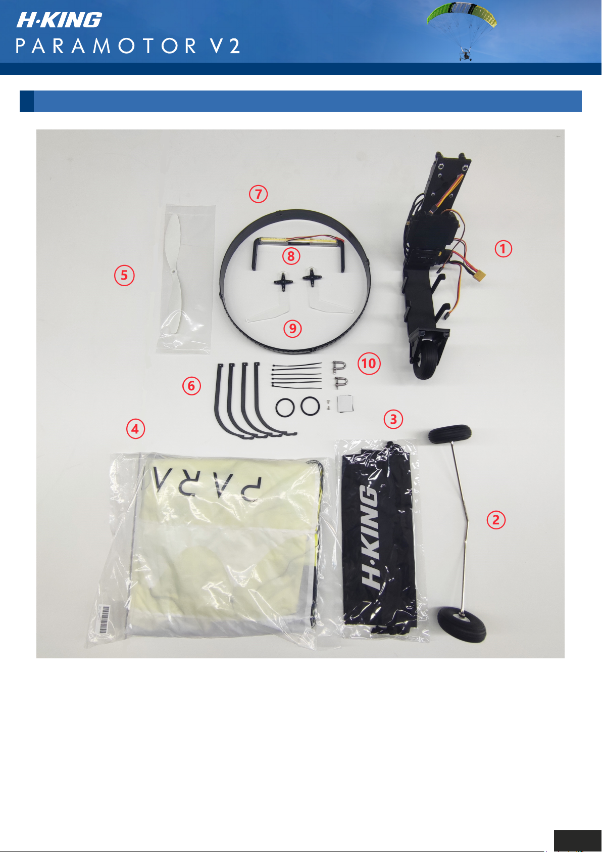
CONTENTS OF KIT
1. Gondola
2. Main Landing Gear
3. Parafoil Storage Bag
4. Parafoil Wing
5. 10x4.7 Propeller
6. Propeller Guard Supports
7. Propeller Guard
8. Flybar w/LED Light Bar
9. Servo Control Arms
10. Accessory Pack
3
Page 6
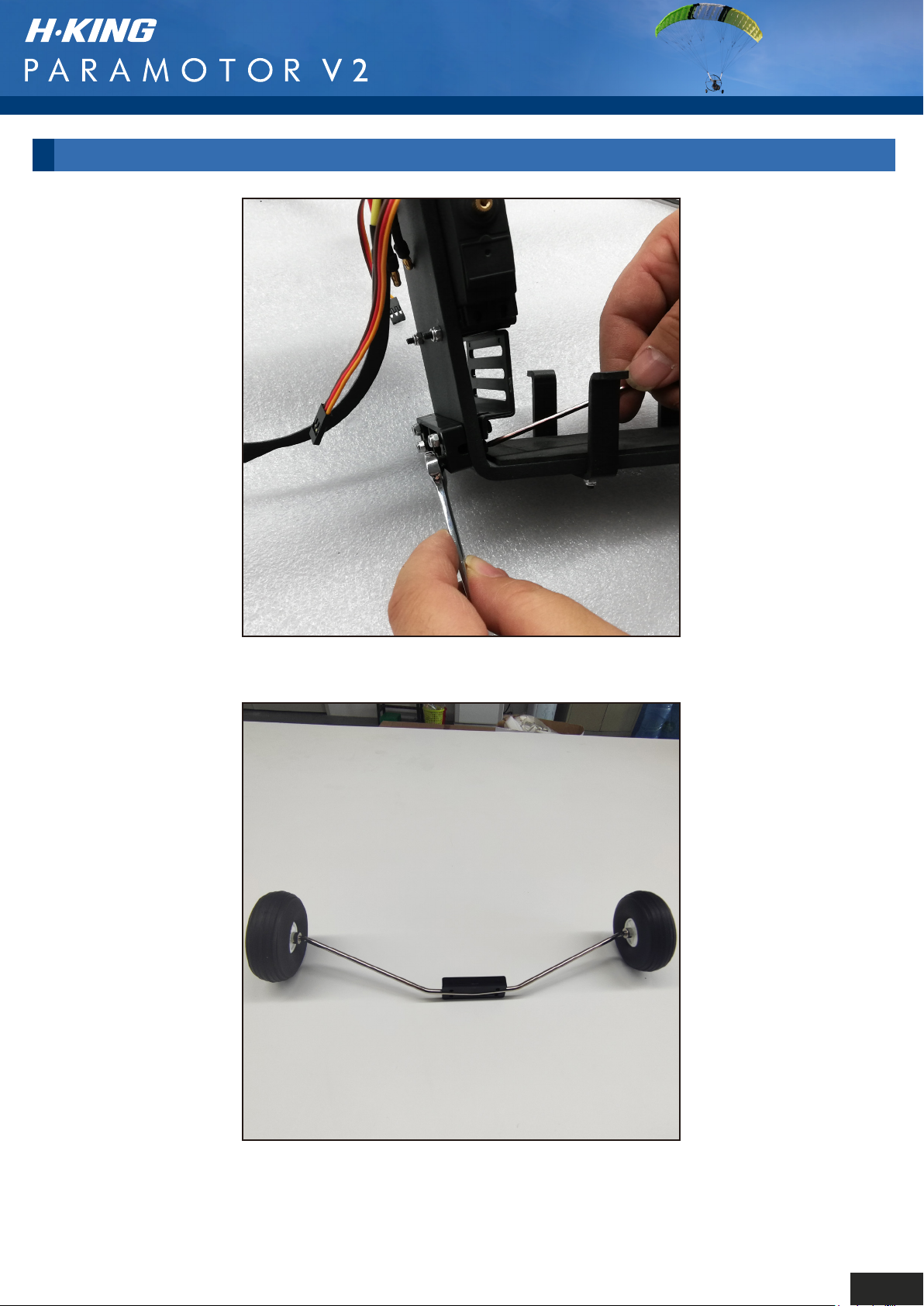
GENERAL ASSEMBLY
Step 1: Remove the undercarriage retaining bracket.
Step 2: Fit the retaining bracket over the undercarriage wire.
4
Page 7
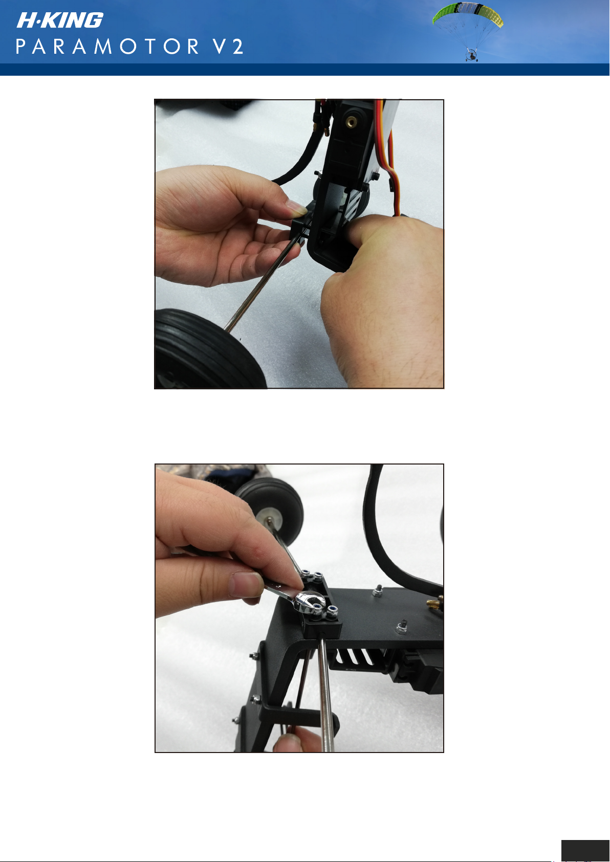
Step 3: Use the hex head screws to refit the undercarriage
bracket with the undercarriage wire positioned between
the bracket and the base of the airframe.
Step 4: Refit the nyloc nuts and tighten the assembly.
5
Page 8
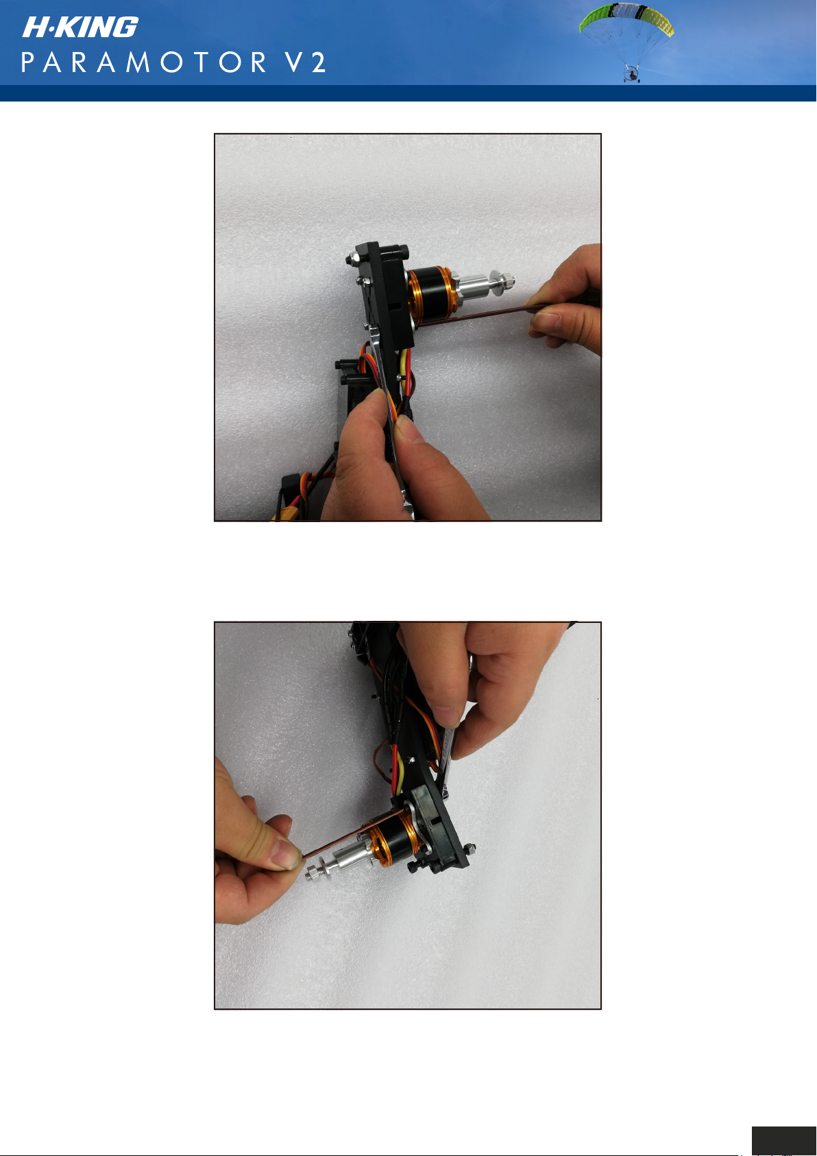
Step 5: At this point we need to remove the motor and
motor mount. The reason for this is that the aluminum
propguard supporting arms have to be installed behind
the mount.
Step 4: Refit the nyloc nuts and tighten the assembly.
6
Page 9
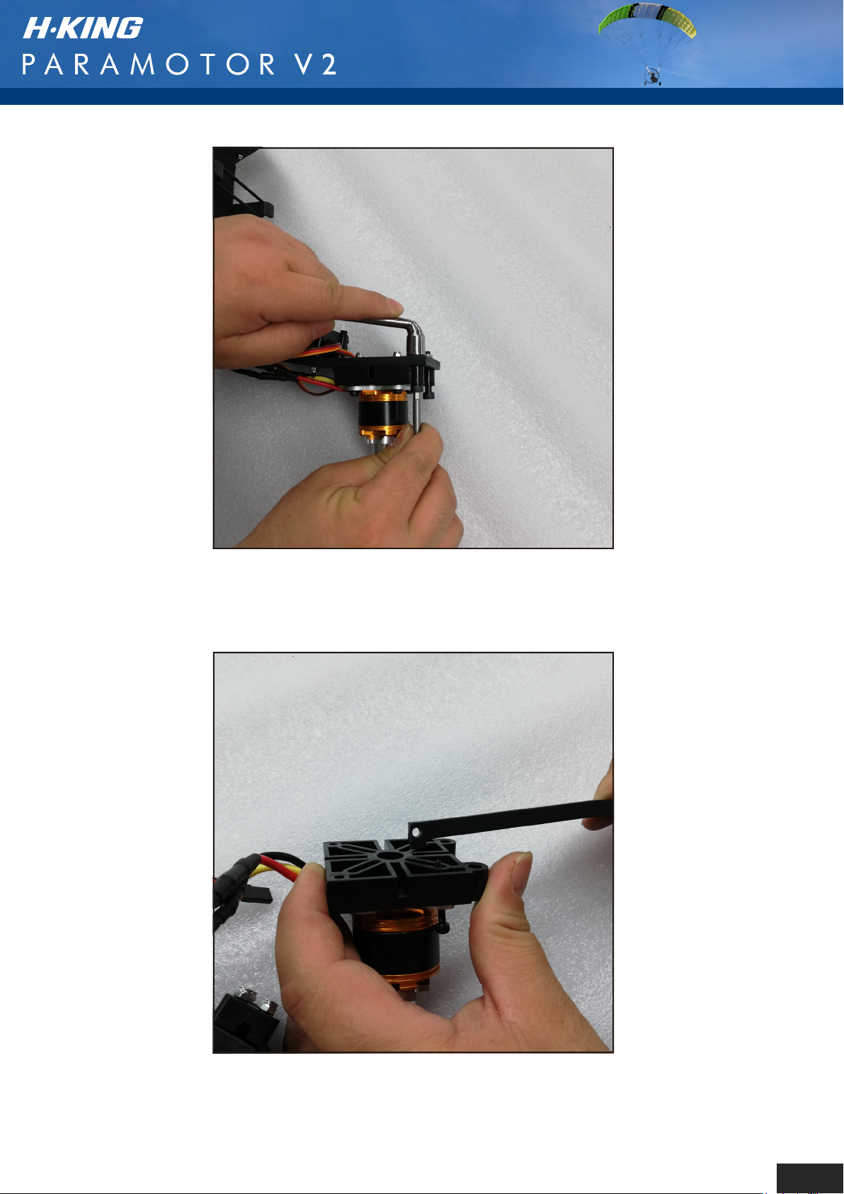
Step 6: Push the hex screws through and remove the
motor and motor mount completely, this makes fitting
the supports easier.
7
Page 10
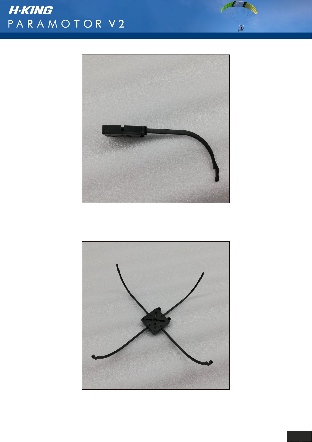
Step 7: Clip the 4 prop guard support arms into the
slots in the rear of the motor mount. These can be quite
a tight fit so you may need to squeeze them fully home
with a pair of pliers or similar tool.
Assembly should look like this when all 4 are clipped
into position.
8
Page 11
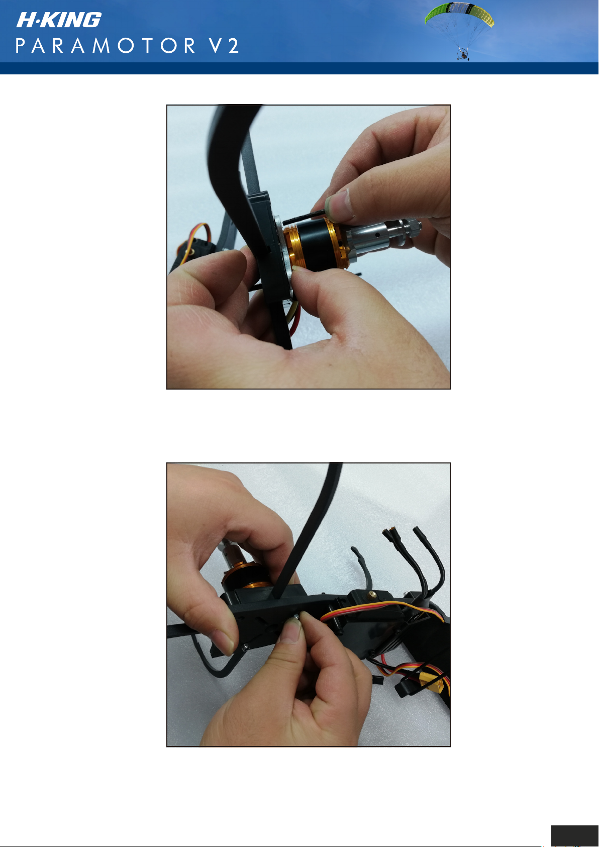
Step 8: As the following pictures show, refit the motor
and motor mount, clamping the prop guard supports
between the airframe and the motor mount.
9
Page 12
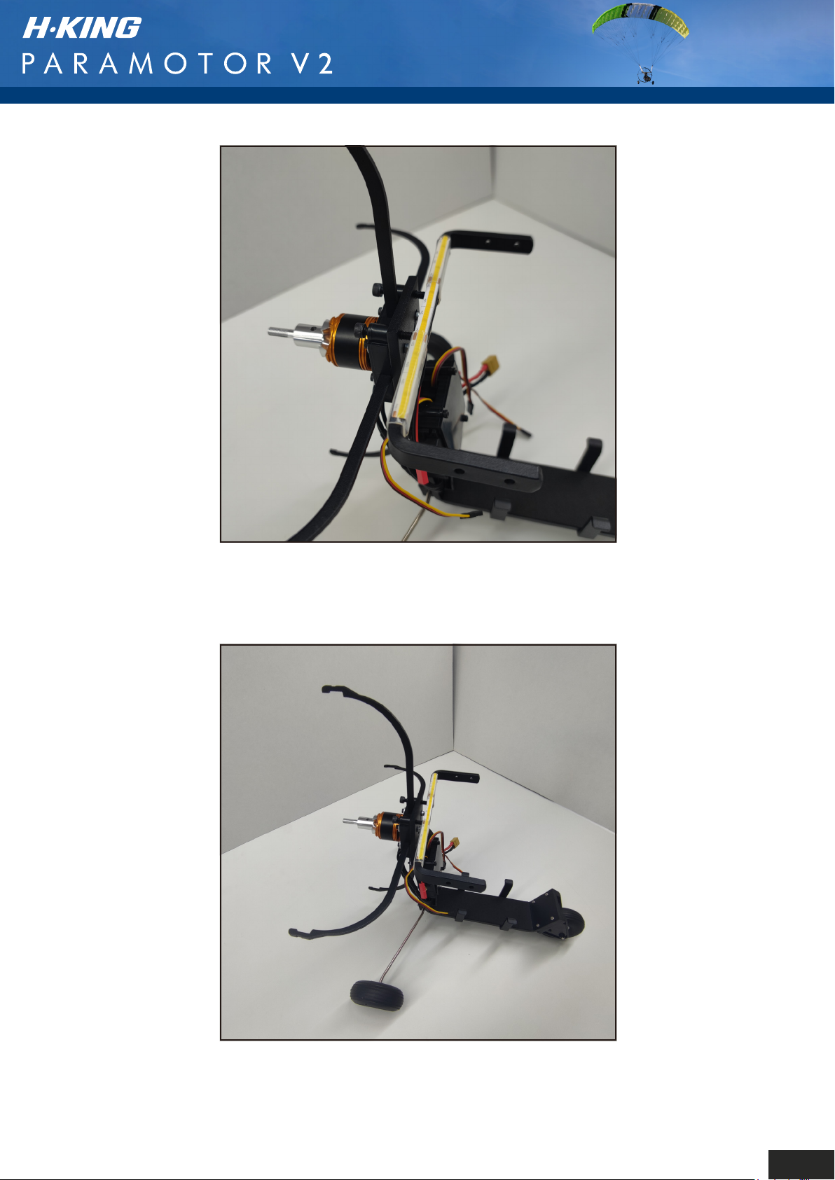
Step 9: Fit the flybar to the front of the airframe using
the longer bolts through the top holes of the motor mount.
10
Page 13
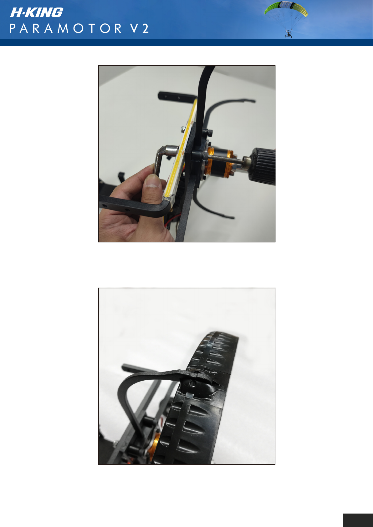
Note: Do not tighten the nuts until you have all 8 bolts
through the mount and frame..
Step 10: The prop guard is aerofoiled, please ensure
you fit it the correct way around, see picture above.
11
Page 14
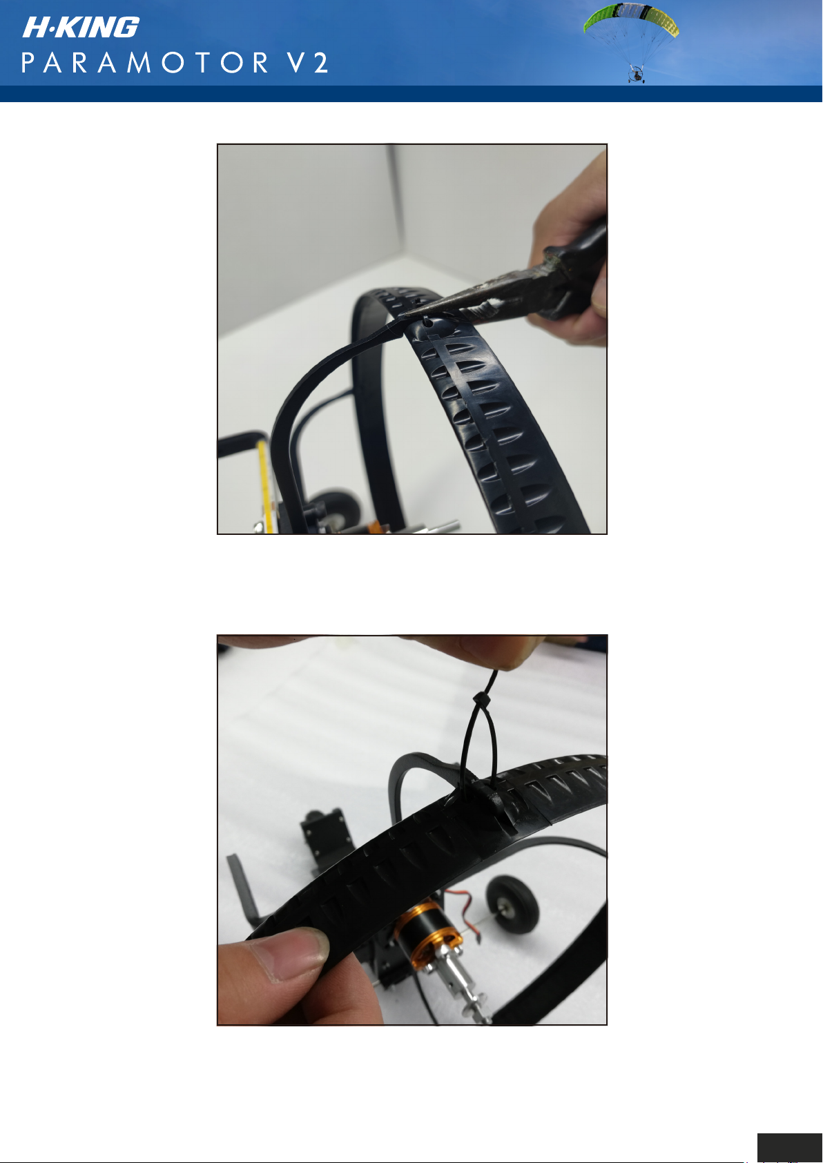
Step 11: Clip all 4 of the prop guard supports into the
slots on the prop guard. These can be quite a tight fit,
so use some pliers to ease them into the slots.
Step 12: Feed a cable tie through the hole in the prop
guard where the support clips to the guard.
12
Page 15
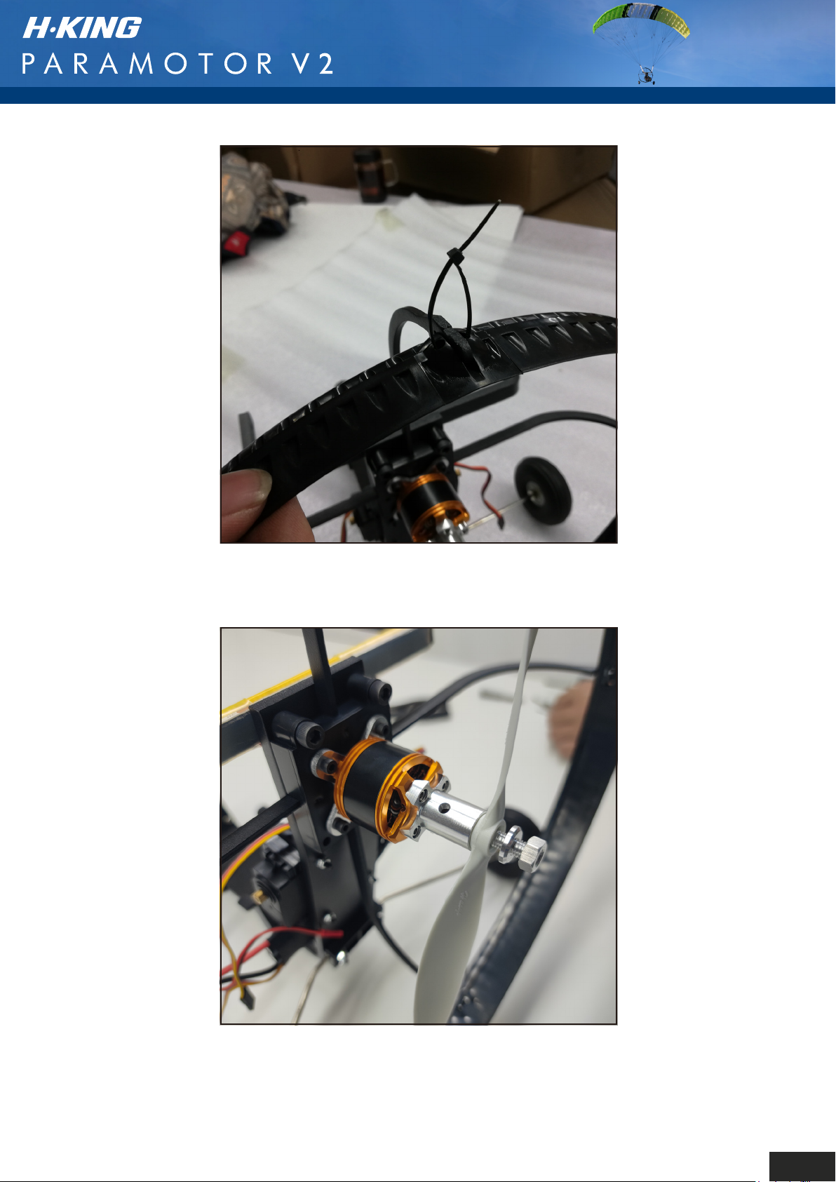
Step 13: Do this to all 4 supports and tighten the cable
ties to secure the prop guard. Make sure you remove
the excess length of cable tie once tightened.
Step 14: Check the balance of the propeller then fit the
assembly as shown. Please ensure you fit the prop the
correct way round as shown above. It is a standard
tractor prop so must face forward in the direction of flight.
We recommend that the propeller is fitted only after you
have setup the servos and the throttle.
13
Page 16
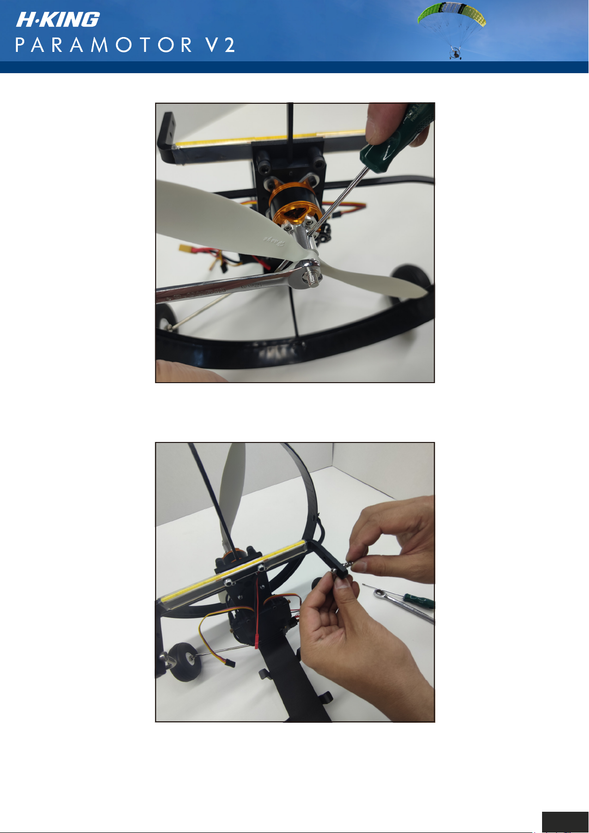
Step 15: Tighten the prop nut using the method shown
in the picture above.
Step 16: The shackles will end up going through the
outer holes either side of the flybar after passing through
the riser lines. This is shown in more detail further on in
the manual when you attach the parawing.
14
Page 17
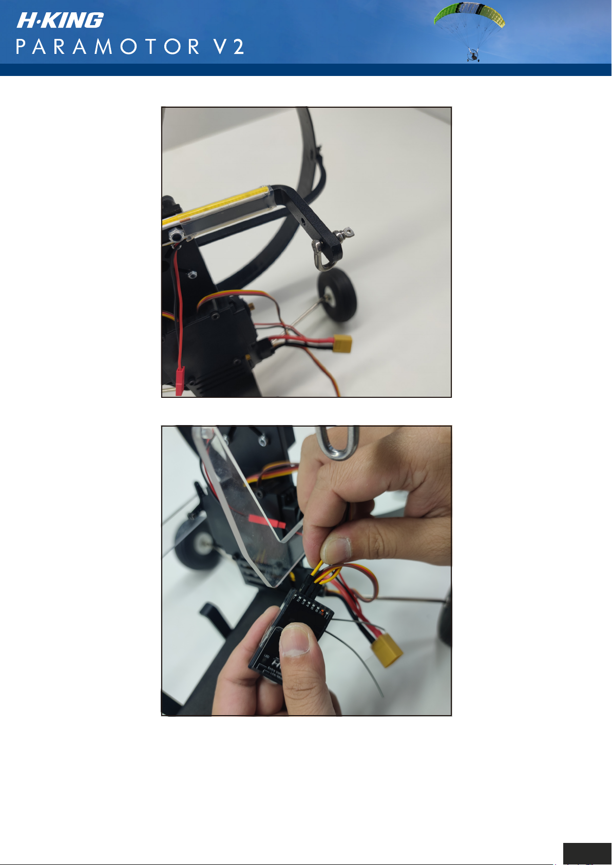
Step 17: Set up your radio and connect the servos to
the receiver. Power up the receiver and center the roll
and pitch servos (watch the set up video before you do
this part). Fit the servo arms with the pre-fitted cranks
onto the splines of the servos. The top hole of the crank
wants to be in line with the top of the flybar or just above.
Secure the arms with the supplied servo screws.
15
Page 18
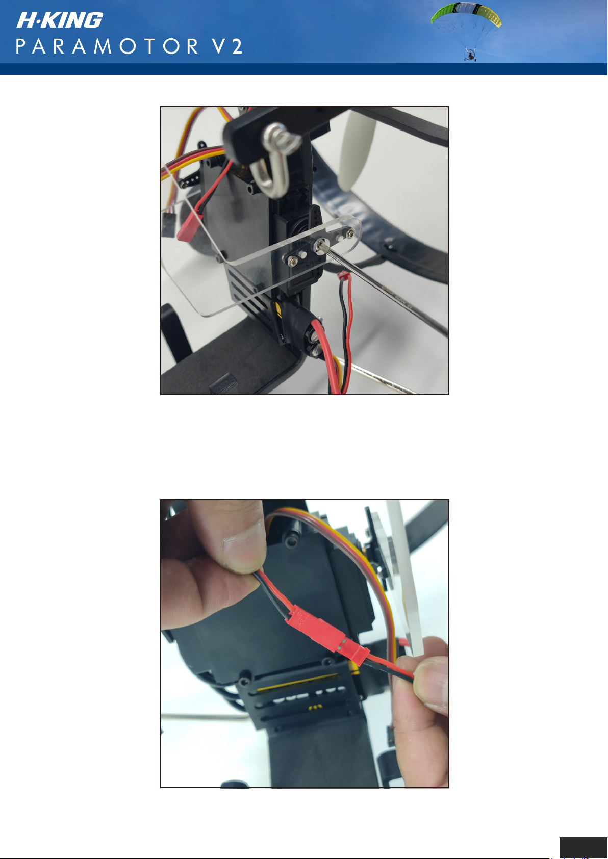
Step 18: Fit the servo arms with the pre-fitted cranks
onto the splines of the servos. The top hole of the crank
wants to be in line with the top of the flybar or just above.
Secure the arms with the supplied servo screws. Secure
your receiver to the servo housing with the sticky back
hook and loop tape.
Step 19: Connect the LED light bar JST plug to the
socket on the ESC. Secure and tidy all the leads and
receiver antenna(s) using cable ties.
16
Page 19
RADIO SETUP
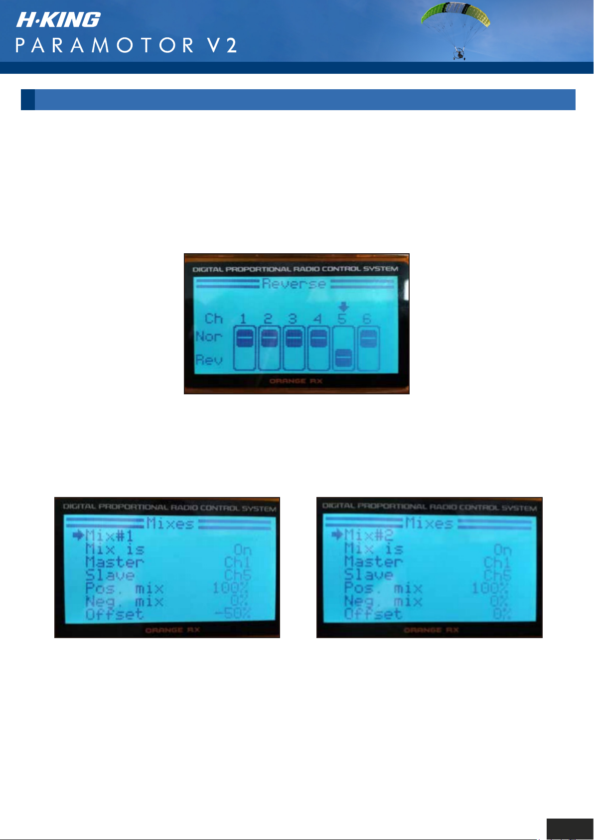
Step 1: Please ensure the propeller has been removed before commencing the radio set up.
Step 2: Set up a new model on your transmitter and bind your receiver.
Step 3: Connect the ESC to the throttle channel, the lefthand servo (looking from behind the gondola)
to CH6, and the righthand servo to CH5.
Step 4: Set the servo reverse direction according to the picture above.
Step 5: Above are some screenshots of the mixing required for a OrangeTx
transmitter, this will also work for JR, and Spektrum.
17
Page 20
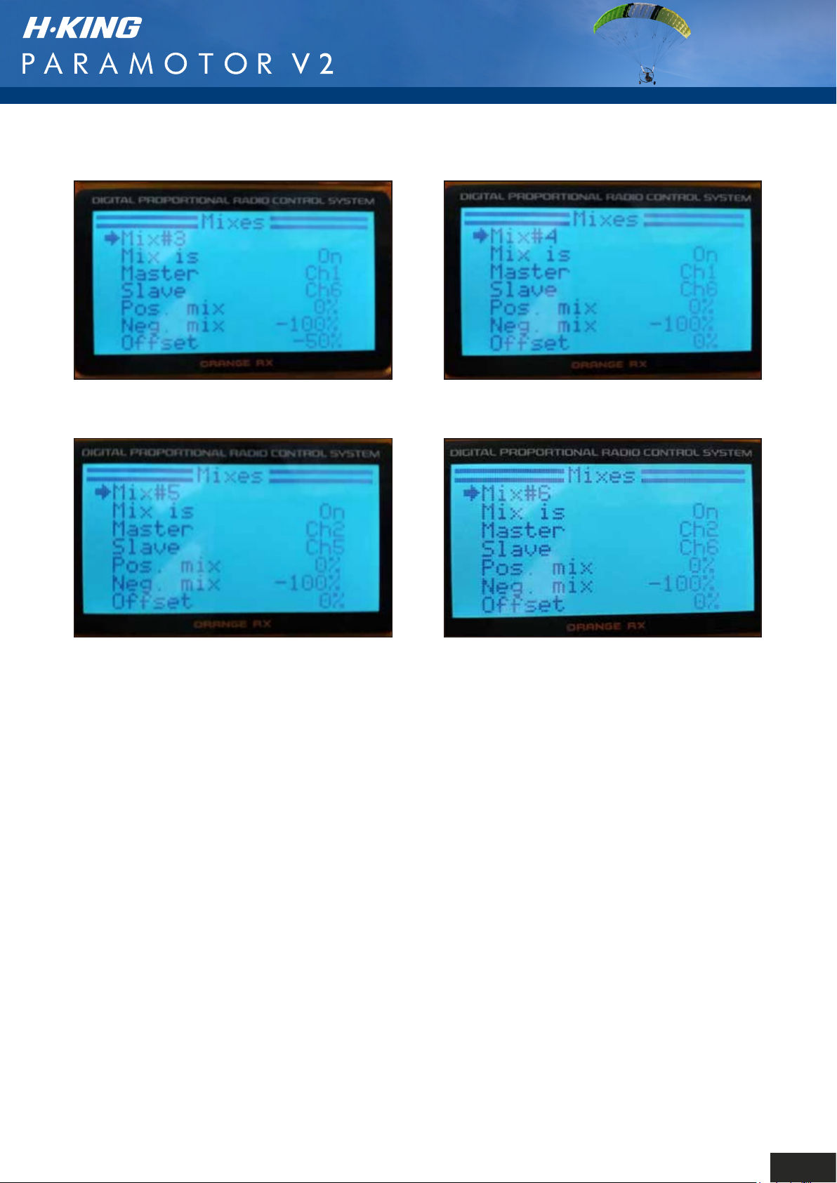
This is the basic airframe finished, the fitting of the Parawing and the setting up of your computer
radio is quite involved. To make life easier, we recommend you watch this video on YouTube in
conjunction with the steps shown further on in this manual to achieve the best results for this
part of the assembly and for setting the radio up.
https://www.youtube.com/watch?v=OqNvJ_UtPqc
Link to video showing a radio setup for Spektrum.
https://www.youtube.com/watch?v=YKngEwop9W4
Please note that you can also use an "Elevon" mix on your transmitter if you have one. Once this
is set and the aileron, elevator functions are mixed, you need to ensure the servos do not move
above neutral, the paramotor does not use any down elevator. To do this, use the servo throw/
end point adjustment of your transmitter. Move the aileron stick to the left, the left servo (looking
from behind) needs to go down, the right servo should stay neutral, reduce the throw on the right
servo until this happens. Repeat this step when moving the stick to the right. When you pull the
stick back, both servos should go down, this is correct. When you push the stick up for down
elevator, the servos should stay neutral, so once more, dial the servo throw down to zero on the
2 elevator channels.
18
Page 21
ATTACHING THE PARAWING
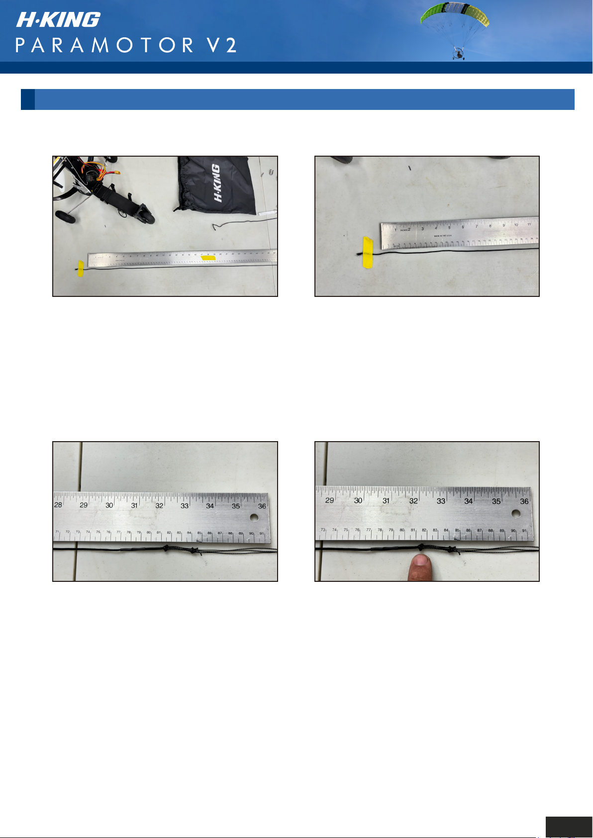
Measuring and tying a knot in the single riser control line.
Step 1: Lay the parawing and the riser lines on your workbench and tape the end of the single,
untied line (the one with a knot in it) of either the left, or right riser line to your bench. We
recommend that you run the line alongside a steel ruler.
Step 2: Stretch the line just a little, not too much, just enough to make the line straight, and
place the middle of the knot on the 81.5cm (32.087") mark of the ruler.
19
Page 22
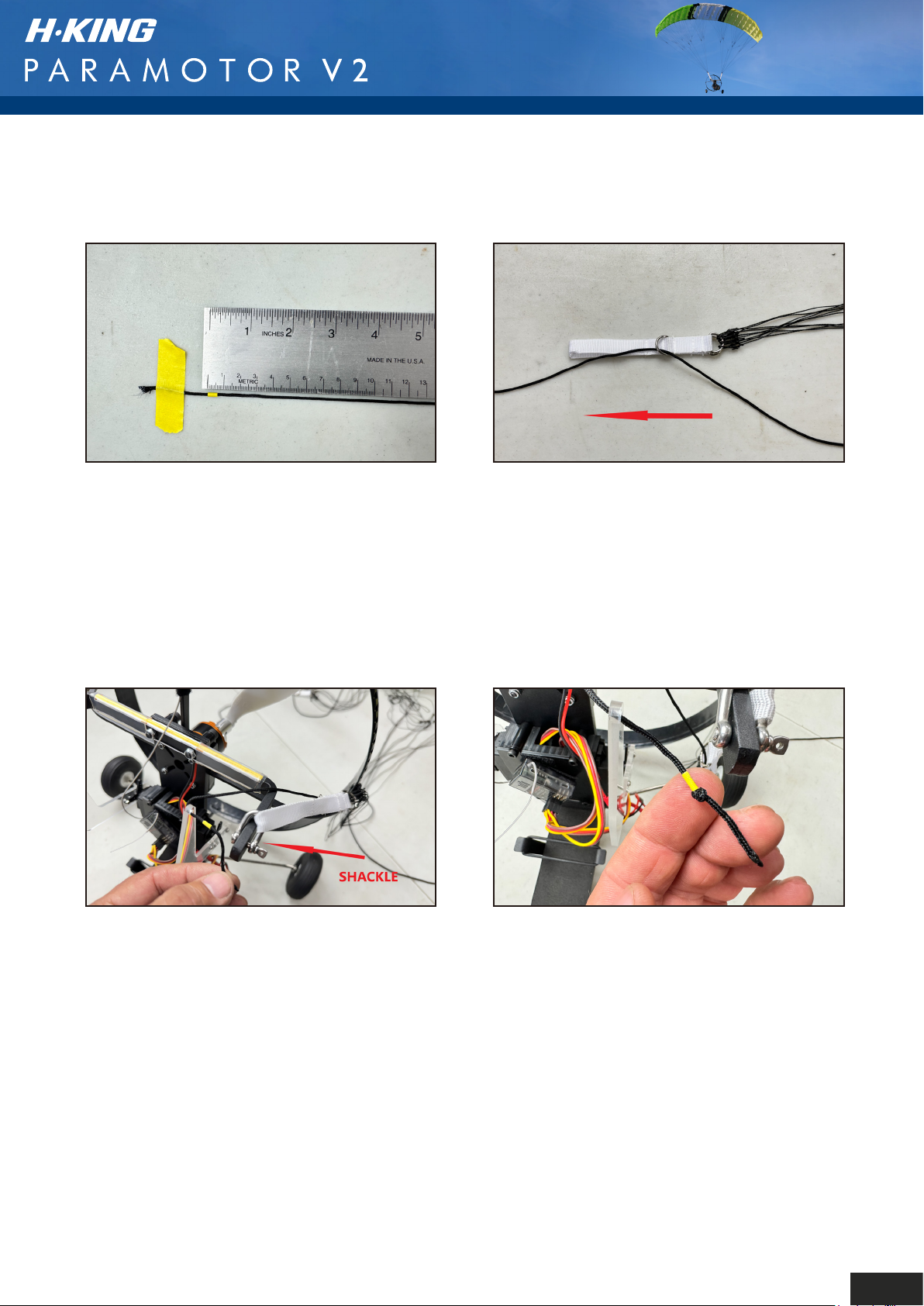
Step 3: At the other end of the ruler, the
zero end, place a small piece of tape as
shown on the zero mark.
Step 4: Remove the line from the workbench
and thread the taped end through the back
hoop (D ring) that is attached to the riser in
the direction of the arrow.
Step 5: Attach the riser to the flybar using
the supplied shackle.Then thread the single
line through the hole in the control arm from
the inside face.
Step 6: You now need to tie a knot in the end
of the line. This knot needs to end up the
thickness of the control arm away from the
leading edge of the tape you applied to the line.
This riser line is now complete, repeat this
exercise for the other side.
20
Page 23
SAFETY INSTRUCTIONS
1. Please read this manual carefully and follow the instructions before you use this product.
2. This Paramotor is not a toy, set up correctly it is suitable for novice pilots. However, if you are a
complete novice it is best to try and enlist the assistance of an experienced pilot.
3. Not recommended for children under 14 years old.
4. Please set up this Paramotor according to the instruction videos and make sure you keep your
hands and other parts of your body out of the way of the rotating propeller at all times. Failure to
do so will result in damage to yourself and to the Paramotor.
5. Do not fly in thunderstorms, strong winds or wet weather.
6. Never fly R/C models where there are overhead power lines, automobiles, airports, railway lines
or near a highway.
7. Never fly R/C models where there are crowds of people or over organised games. This Paramotor
requires an open field that is clear of trees and other obstacles. Remember safety is the
responsibility of the pilot.
8. Do not attempt to catch this model when you are flying it unless you have a lot of experience
doing so.
9. The operator will bear the full responsibility of flying and the proper operation and usage of this
model. We at Hobbyking will not be responsible for any liability or loss due to improper use of this
model.
21
Page 24
FLYING THE PARAMOTOR V2
The H-King Paramotor V2 is straightforward and fun to fly, but some basic things make it slightly
different from conventional fixed-wing airplanes. With the aid of a helper it can take off from the
ground, but under normal circumstances, it is best to hand-launch it. The main difference to
conventional airplanes is that there is no elevator as such, the up elevator control is really a brake
for slowing the Paramotor down. Then the throttle is used for climbing, and descending, more power
makes it climb, less power and it will descend. The Paramotor does not need a lot of power,
especially when launching, or even when flying generally. Too much power will very quickly get
things out of shape, the throttle should be used smoothly and gently when you are making power
changes.
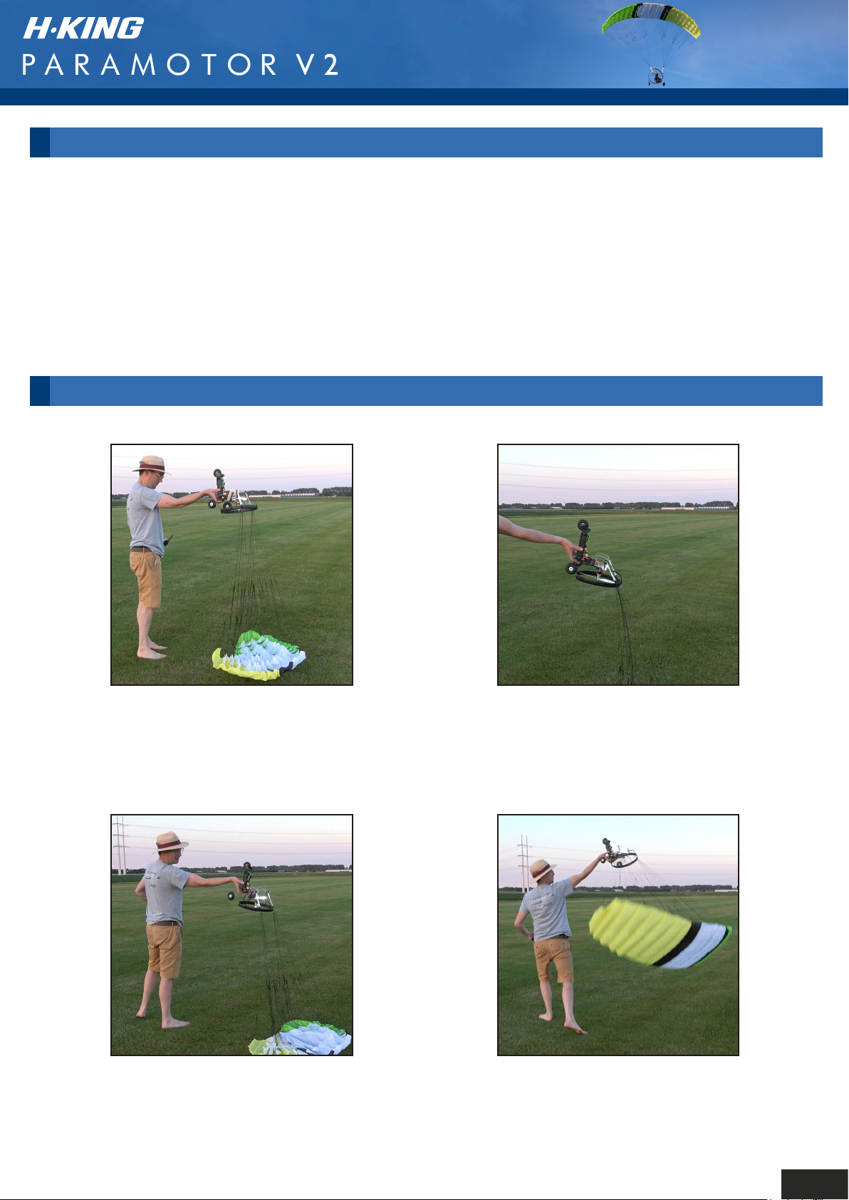
LAUNCHING
Step 1: Please make sure the parafoil
is laying flat on the ground and the riser
lines are nice and straight and not tangled.
Step 3: Please ensure you are facing
and launching into wind, then open
the throttle to about 35% (1/3rd
throttle) and no more.
Step 2: Hold the gondola as shown
with you with you thumb and 4th finger
either side of the frame, and your index
and 3rd finger on the back of the frame.
Step 4: Then when everything feels
right and is nice and stable, perform
a smooth overarm throw as if you are
bowling a cricket ball.
22
Page 25
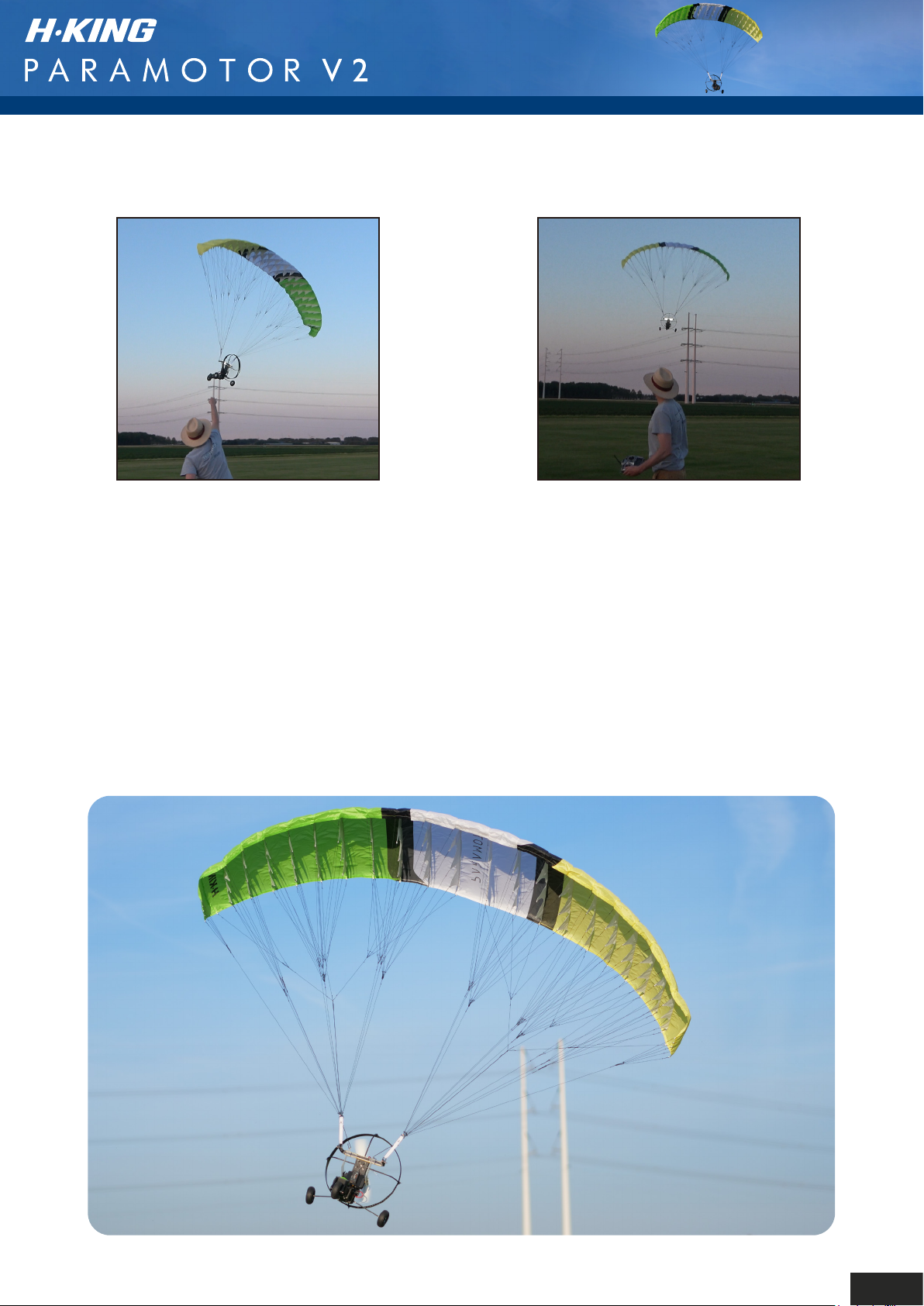
Step 5: Just as you get to the top of
the launch give a slight tug downwards,
this helps inflate the wing, then let go.
Note: A flying video is available (link below), or click on the link under the video
section of the listing for the H-King Paramotor V2 on the Hobbyking.com website.
Step 6: The Paramotor V2 should now
climb away nicely still at about third
throttle. If it all starts to go a bit wrong as
you launch then abort, set things back up
and try again.
https://www.youtube.com/watch?v=E7BnNsdOiu0
23
Page 26
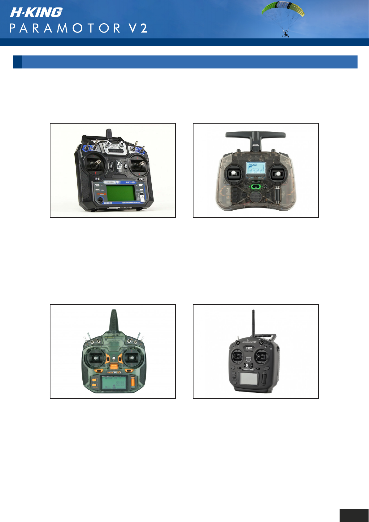
RECOMMENDED ACCESSORIES
Turnigy TGY-i6 Mode 2 AFHDS
Transmitter and 6CH Receiver
SKU: 9114000020-0
RADIOMASTER (Charcoal) Pocket ELRS
FCC 2.4GHz Compact 16ch Transmitter
w/Open-Source Edge TX Firmware
SKU: 1022720065
OrangeRx Tx10i Mode 1 EU Version 10ch
2.4GHz DSMX Compatible Radio System
SKU: 9171001398-0
RADIOMASTER TX12 MKII CC2500 LBT
2.4GHz Compact 12ch Transmitter w/
Open-Source Edge TX Firmware
SKU: 1022720012
24
Page 27
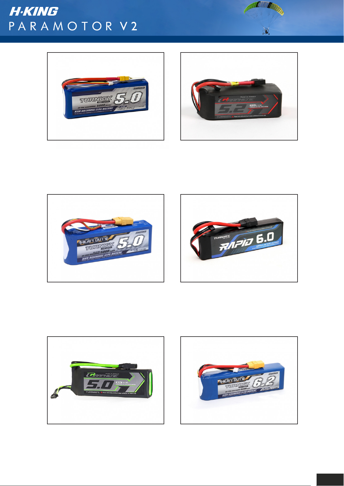
Turnigy 5000mAh 3S 20C Lipo
Pack w/XT-60
Turnigy Graphene Professional
5200mAh 3S 15C LiPo Pack w/XT60
SKU: 9114000020-0
Turnigy Heavy Duty 5000mAh 3S
60C LiPo Pack w/XT-90
SKU: 9067000236-0
SKU: 9067000105-0
Turnigy Rapid 6000mAh 3S (11.1V)
100C LiPo Battery Pack w/XT90
Connector
SKU: 9067160568
Turnigy Graphene Panther
5000mAh 3S 75C Battery Pack
SKU: 9067000374-0
Turnigy Heavy Duty 6200mAh 3S
60C LiPo Battery Pack w/XT90
SKU: 9067000544-0
25
Page 28
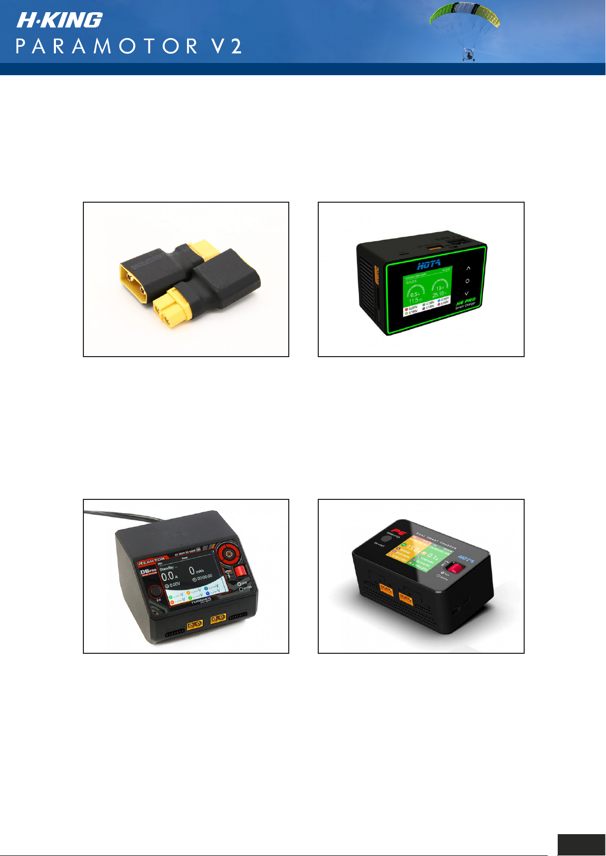
XT90 Male to XT60 Female Adapter
2pcs
HOTA H6 Pro AC/DC 200W AC/700W DC
1~6S Smart Charger
SKU: 258000140-0
Turnigy Reaktor D6 Pro Duo 2x325W
(650W) Balance Charger AC/DC w/
Wireless Charging
SKU: 9466000018-3
SKU: 9466000020-3
HOTA P6 2 x 300W 1~6S Dual Smart
Charger/Discharger (DC Only)
SKU: 9466000021-0
26
Page 29
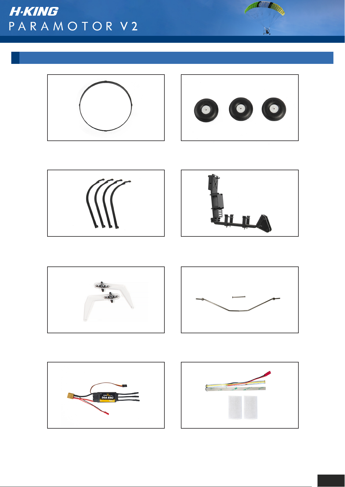
SPARE PARTS
Propeller Guard
SKU: 9310000405-0
Prop Guard Stays
SKU: 9310000407-0
Wheel Set
SKU: 9310000406-0
Main Frame
SKU: 9310000408-0
Control Arms
SKU: 9310790505
50A ESC w/Light Bar JST
Connector
SKU: 9310790507
Main Landing Gear Set
SKU: 9310790506
LED Light Bar Set
SKU: 9310790508
27
Page 30

 Loading...