

Page 1
Page 2
INTRODUCTION:
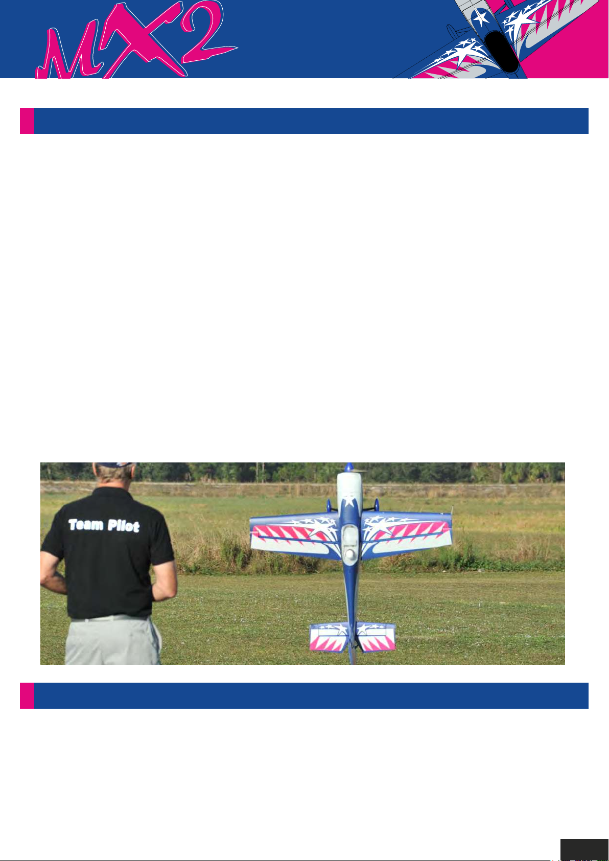
The H-King MX2 3D was designed to be an all-out 3D performer with great, straight precision flying
capabilities. It has a great combination of lightweight, durability, and performance with none of the
compromises normally found in EPO foam aerobatic models. Michael Wargo, our team pilot, and 3D
expert helped fine-tune the MX2 Extreme 3D into the type of plane he enjoys flying. The result is an
aircraft that delivers lightning-fast rolling, amazing straight lines,and extreme tumbling, but it also likes
to perform all of the low and slow 3D maneuvers pilots love.
The MX2 is the perfect aircraft for any pilot wanting a versatile and capable 3D plane. This MX2 is the
next generation of EPO foam designs that are lighter and more capable than ever. Any accomplished
3D pilot will love this plane because it will satisfy the most discriminating pilot. Its high-energy
performance defines this plane, but bring it in low and slow, and it is rock solid and easy to harrier and
hover.
This Plug-N-Fly 3D airplane is very quick and simple to assemble and is supplied in a striking red,
white, and blue pre-printed finish, with carbon landing gear, wheels, and wheel spats. Power is
supplied by the pre-installed 3702-900KV brushless motor driving a fine pitch 13x4 composite
propeller, and a 60A ESC, this is the perfect set-up for excellent throttle response when performing
3D. Also supplied and pre-installed are 4 x 13g high-speed, metal-geared digital servos, these
high-quality servos have an excellent resolution and speed for precise control.
The MX2 Extreme is easy to transport due to its removable wings and is fantastic fun to fly just about
anywhere. If you are looking for an airplane to progress into 3D aerobatic flying, and to take your
flying skills to the next level, then the H-King MX2 Extreme is the perfect choice.
SPECIFICATIONS:
- Wingspan: 1270mm
- Length: 1210mm
- Materials: EPO
- Flying Weight: 1240g (excluding battery)
- Battery: 2200mAh 4S (14.8V) 45~90C LiPo w/XT60 (not supplied)
- Flight Time: Approx 5mins with 2200mAh battery
- Propeller: 13x4
- Radio: 4ch or more
- ESC: 60A brushless with 4A switching BEC
- Motor: 3720-900KV brushless
1
Page 3
2
Page 4
INTRODUCTION:
1
2
3
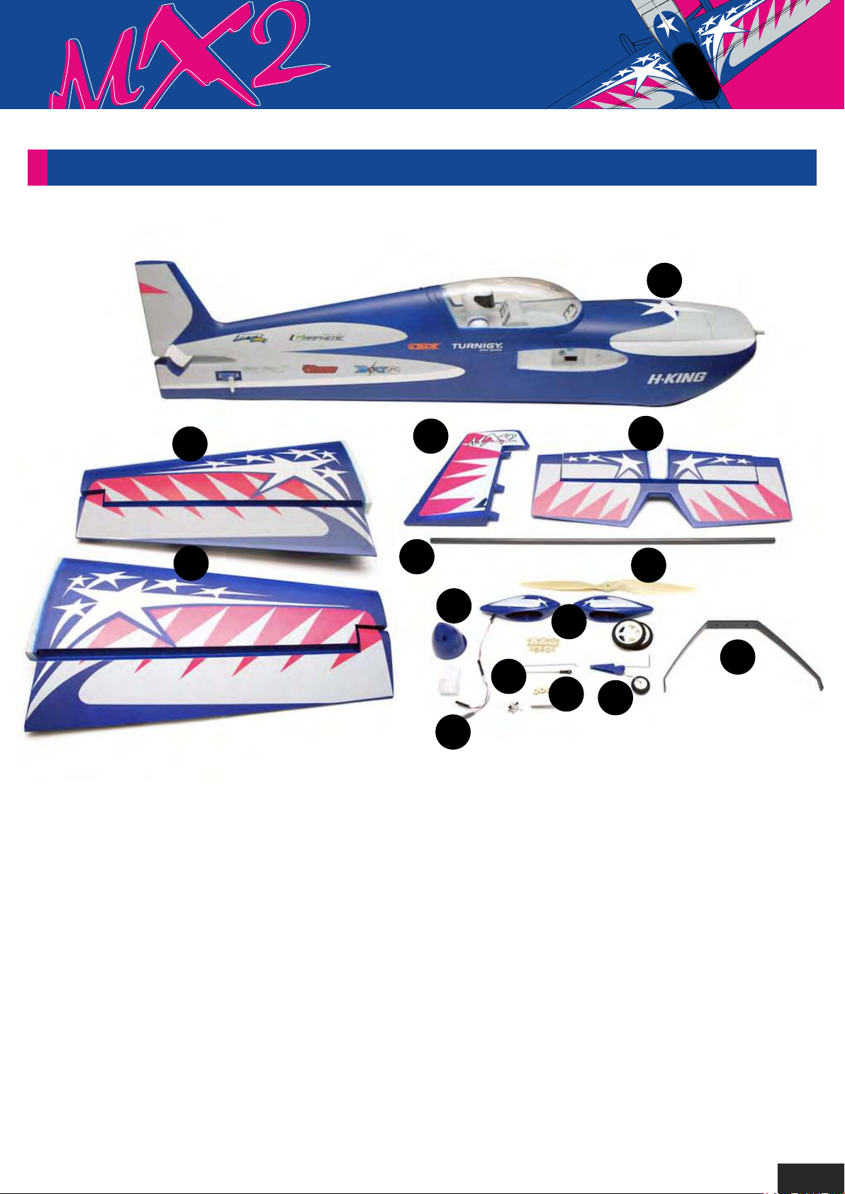
1. Fuselage
5
6
12
13
9
8. 13 x 4 Propeller
14
15
4
8
11
10
2. Left main wing
3. Right main wing
4. Wing protectors
5. Rudder
6. Carbon fiber wing joiner rod
7. Wheel spats and wheel sets
9. Servo Y lead
10. Tail-wheel bracket
assembly
11. Carbon fiber landing gear
12. Spinner
13. Pushrod linkages
14. Wheel spats and wheels
15. Plywood washer
3
Page 5
ASSEMBLY INSTRUCTIONS:
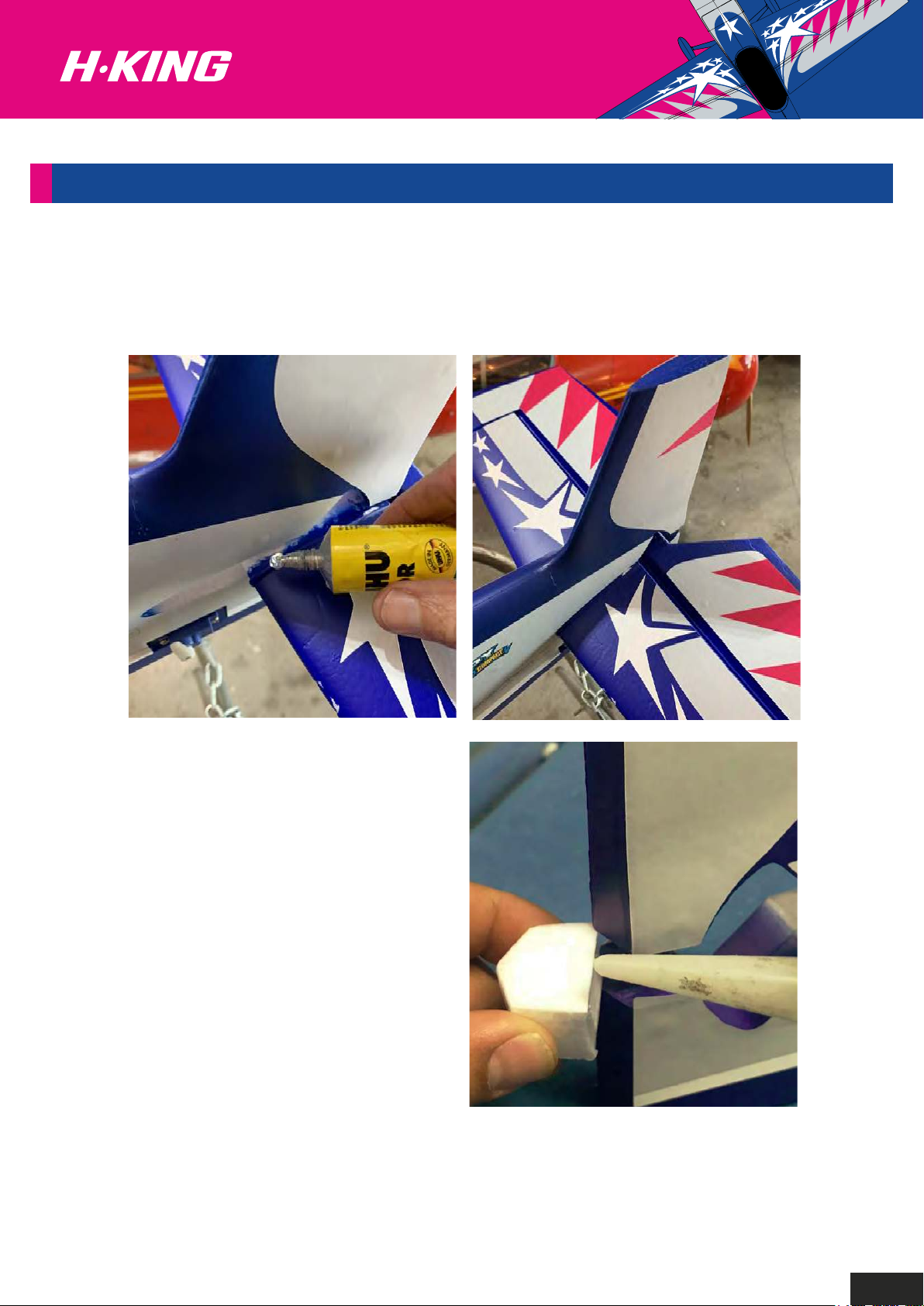
Horizontal Stabilizer Installation.
Apply a thin coat of foam safe glue to the stabilizer mid-section and gently slide it into place as shown.
Check frequently if the stabilizer is level and square to the fuselage as the glue dries.
A small piece of white foam comes with the
fuselage. Apply some foam safe glue and place
into the slot between the lower part of the rudder
post and the rear of the fuselage to further
reinforce the structure of the empennage.
4
Page 6
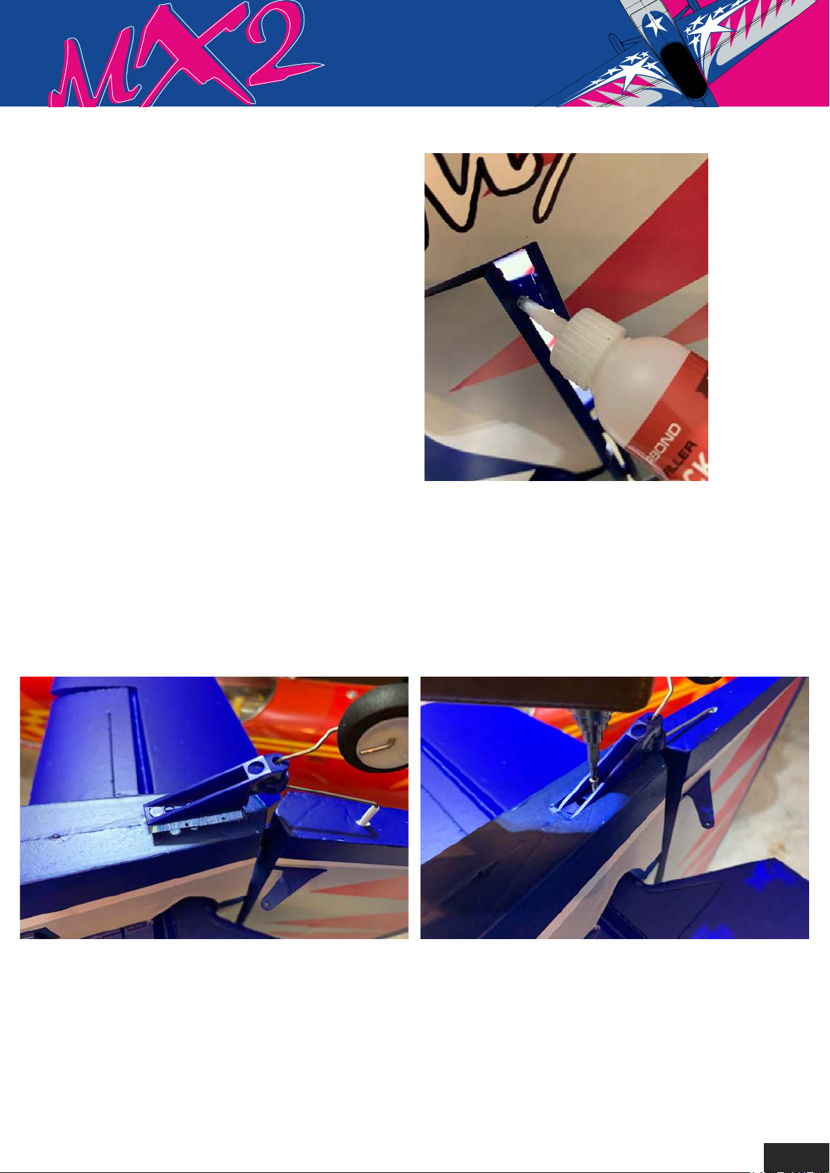
Rudder installation.
Insert the pre-installed rudder hinges into the
fin and apply foam safe CA glue to secure in
place. Check frequently to ensure that the
rudder moves freely as the glue dries.
Tail wheel installation.
Insert the tail wheel landing gear wire into the small hole in the rudder. Then install the
plastic bracket on to the rear of the fuselage and secure it using the supplied 3mm
self-tapping screw as shown.
5
Page 7
Rudder installation.
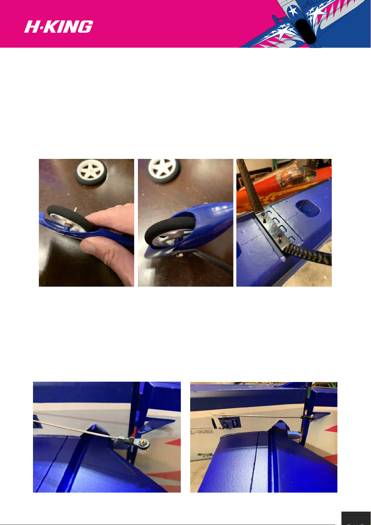
Install one of the supplied M3 x 35mm bolts through one of the wheel spat outer halves and add a
plywood washer and wheel as shown. Then slide on the inner half of the wheel spat, pass the
remaining part of the bolt through the hole in the carbon landing gear, then secure the spat/wheel
assembly in place by using the supplied M3 nut. Apply some thread locker to the thread to prevent any
loosening in flight. Repeat this process for the other spat and wheel. Secure the carbon fiber landing
gear onto the landing gear mount on the underside of the fuselage using the supplied M4 x 30mm
screws as shown.
Rudder and elevator pushrod installation.
Before you install the pushrod to the servo, ensure the servo control arm is perpendicular to the servo
case. Install the end of the pushrod with the Z bend on into the outer most hole on the servo control
arm. Then connect the ball socket end onto the rudder surface control horn, secure it with the supplied
screw and retaining nut. Apply some thread locker to keep it secure.
Repeat the above steps for the elevator control linkage installation.
6
Page 8
Main wing installation.
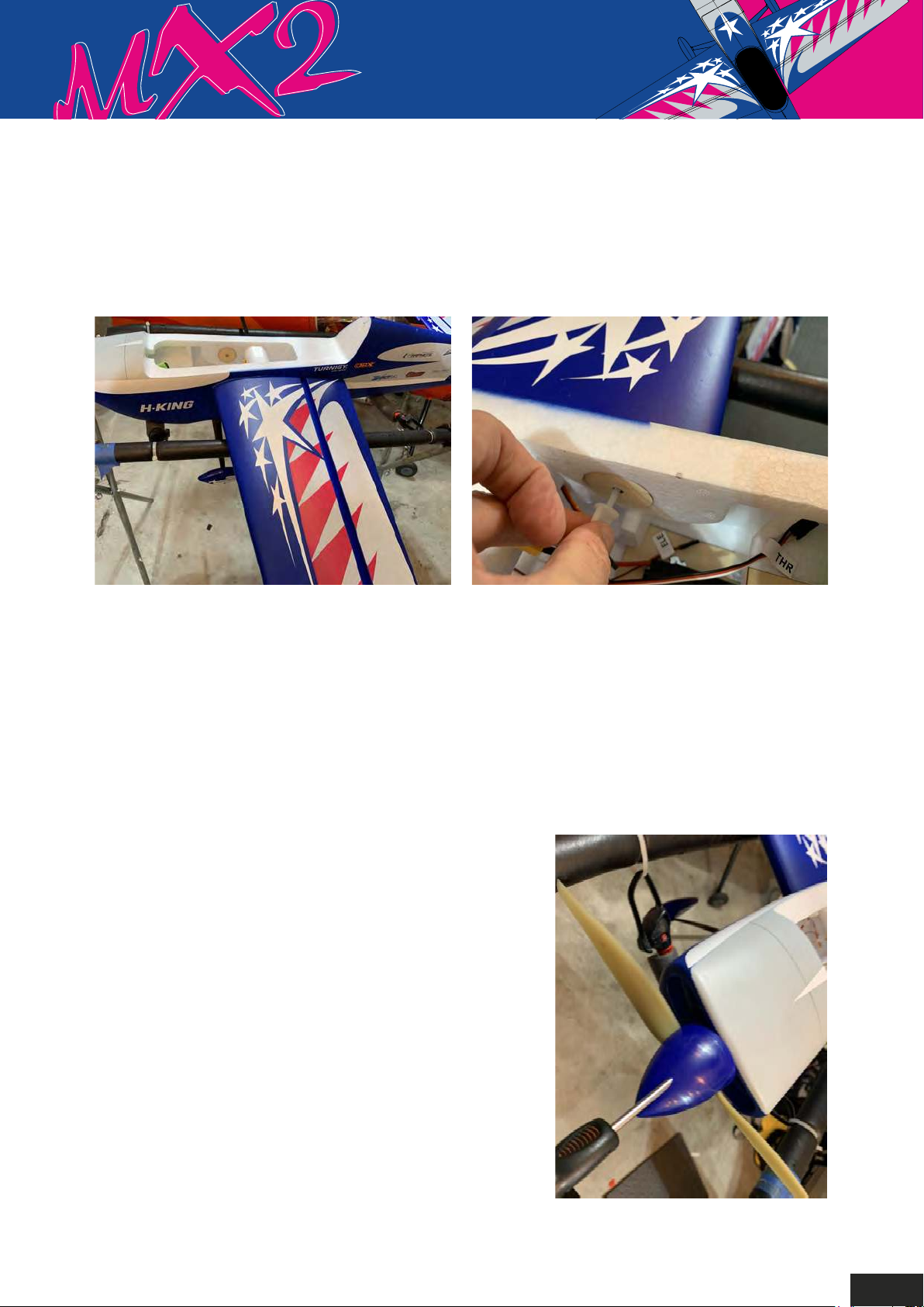
Install the carbon wing joiner rod through the fuselage. Then slide the left wing panel onto the rod and
feed the aileron servo lead through the hole in the fuselage at the same time. Secure the wing panel by
using the supplied nylon wing bolt. Repeat the above steps for the right wing panel installation.
Prop and spinner installation.
1. Install the prop hub adapter onto the motor shaft.
2. Install the spinner back plate onto the prop adapter, followed by the propeller.
3. Install the washer and the M8 nut, tighten the nut with a spanner. Attach the spinner nose cone to
the backplate using the supplied self-tapping screws. You may need to adjust the backplate and the
spinner cone accordingly by loosening the prop nut and moving it a fraction until the screw holes are
perfectly aligned together.
4. When you are satisfied with the fit, tighten the prop nut
and secure the spinner with the self-tapping screws.
Note: To achieve the best possible power and
performance from the power train as well
as ensuring you reduce the vibration on the airframe,
always balance the propeller and
spinner properly before flying.
7
Page 9
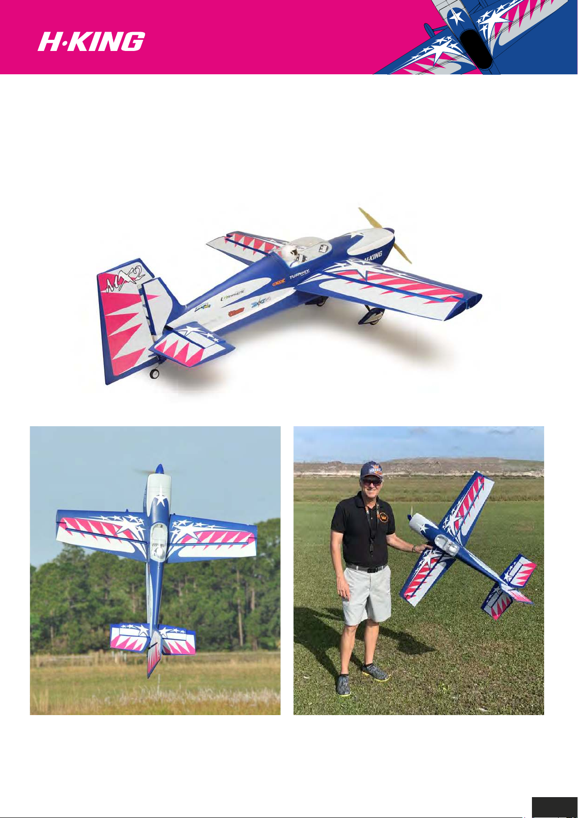
Your H-King MX2 Extreme 3D
is now complete.
8
Page 10
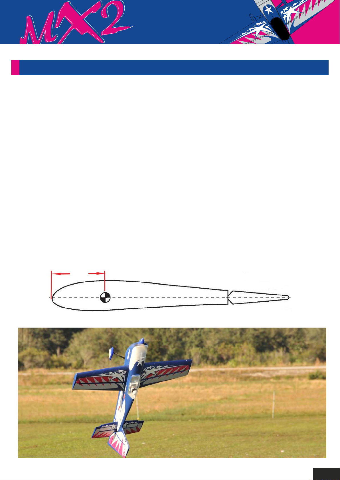
SETTING-UP THE H-KING MX2 EXTREME 3D:
Travel Settings:
Each flight control must be set to its physical limits. This means as far as it will go, but no farther
than it has to. You set this by selecting the servo, fully deflect the surface with the transmitter,
then increase (or occasionally decrease) the percentage to where the flight surface will not
travel any further. Then simply back off a click or two and you are done. Then, deflect it in the
opposite direction and repeat the process. This must always be done for rudder, ailerons, flaps
and elevators. Your travel/end point settings must be above 100% to achieve full performance
from each servo.
Rates and Exponential
All rates at 100% for full 3D flying. Put the stick at one third and set to where when you switch
between rates the surface hardly changes. Obviously at the end points it is an enormous difference.
Our Recommended expo settings for low rates is in the 20% range for an aerobatic plane, and expo
in the 60% to 70% range for high rates for 3D.
C of G Position:
95mm
to
100mm
Happy Flying!
9
Page 11
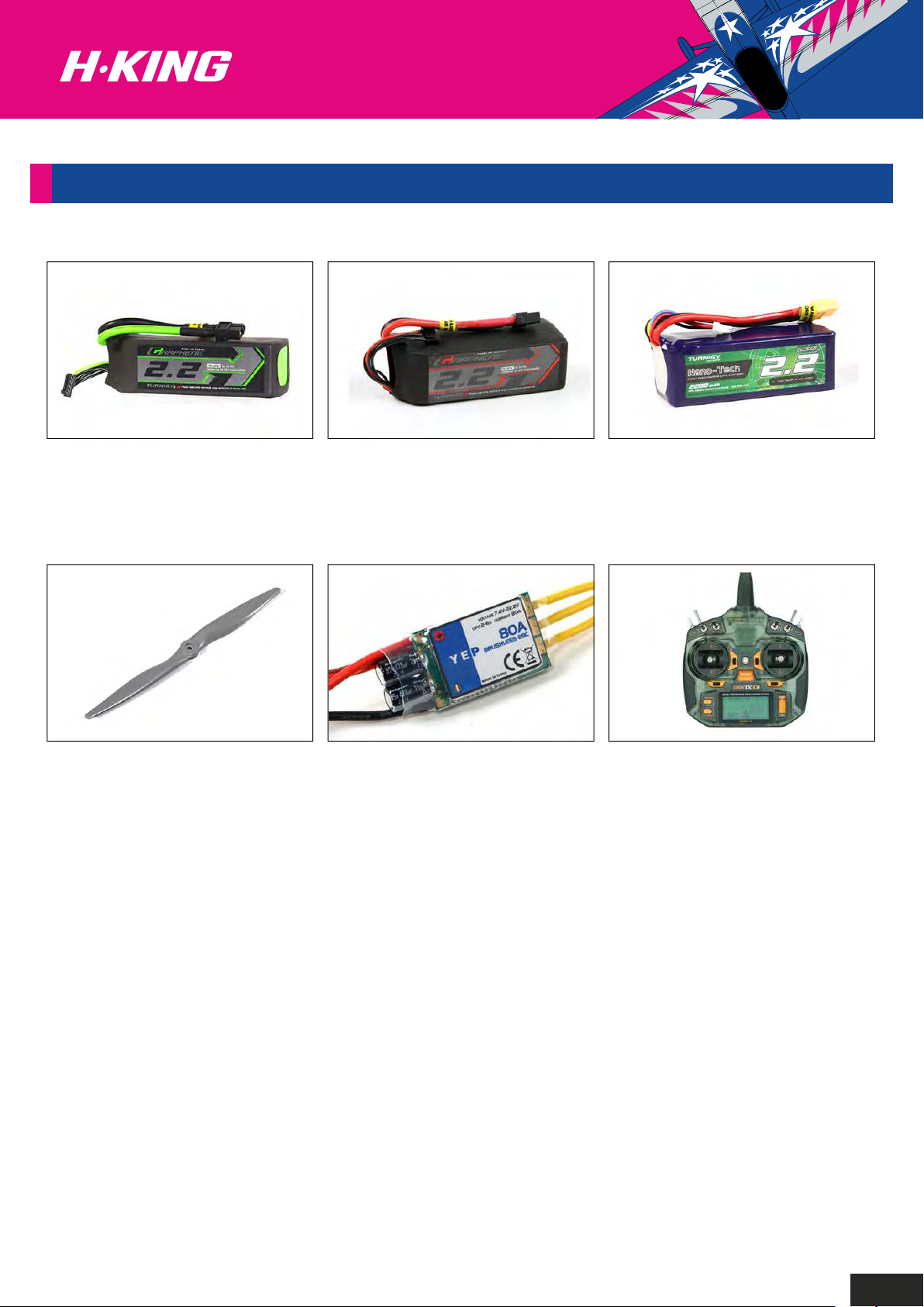
RECOMMENDED PRODUCTS:
Turnigy Graphene Panther
2200mAh 4S 75C Battery Pack
SKU: 9067000372-0
Aerostar Composite Propeller
13x4 Grey (1pc)
SKU: 9329000187-0
Turnigy Graphene 2200mAh 4S
45C Lipo Pack w/XT60
SKU: 9067000136-0
YEP 80A (2~6S) SBEC
Brushless Speed Controller
SKU: 9351000017
Turnigy Nano-Tech Plus
2200mAh 4S 70C Lipo Pack
w/XT60
SKU: 9210000301-0
OrangeRx Tx10i Mode 2 EU
Version 10ch 2.4GHz DSMX
Compatible Radio System
SKU: 9171001399-0
10
Page 12
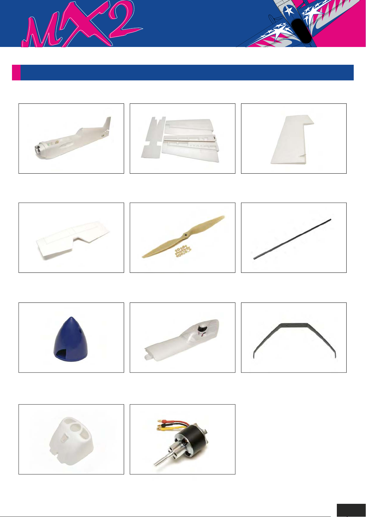
SPARE PARTS
Fuselage
SKU: 9152000026-0
Horizontal stabilizer
SKU: 9152000030-0
Main wing set
SKU: 9152000027-0
13 x 4 prop
SKU: 9152000035-0
Rudder
SKU: 9152000031-0
Carbon fiber wing joiner
SKU: 9152000032-0
2 blade spinner
SKU: 9152000033-0
Cowling
SKU: 9152000028-0
Canopy hatch
SKU: 9152000029-0
Motor
SKU: 9152000036-0
Carbon fiber landing gear
SKU: 9152000034-0
11
Page 13
UK REP
EC REP
APEX CE SPECIALISTS LIMITED
89 Princess Street, Manchester,
M1 4HT, UK
APEX CE SPECIALISTS LIMITED
Unit 3D North Point House,
North Point Business Park,
New Mallow Road, Cork, T23 AT2P, Ireland
 Loading...