

Page 1

Assembly and operating instructions
Specification
● Wing Span: 19-5/7" (500mm)
● Length: 27-1/2"(700mm)
● Flying Weight: 11-3/5 oz (330g)
Assembly and Operating Manual
Page 2

Assembly and Operating Manual
Dear customer,
Congratulations on your choice of a
factory-assembled model aircraft from the
SKYANGEL Hummingbird range and thank you
for placing your trust in us.
Very little preparation work is required to get this
model ready to fly. To operate your new model
safely it is important that you read through all of
the instructions and safety information included
with your model, before you fly it for the first time.
The illustrations in this manual show the Blue Star
version of the model with factory applied decals.
The power system
The model is powered by a brushless outrunner
motor and ducted fan, both of which are
factory-installed on the Ready-To-Fly version.
The motor is connected to the electronic speed
controller which is factory calibrated on the
Ready-To-Fly version. All that is required is to
charge the Li-Po battery, following the safety
instructions, and connect
the battery to the
electronic speed controller.
The radio control system
To fly the AMX you will need a radio control system
with at least four channels. 2.4GHz radios systems
are recommended, similar to the unit included with
our deluxe version.
The servos for the ailerons and the elevators are
factory-installed.
The power for the receiver is drawn from the
electronic speed controller’s integral BEC system.
The electronic speed controller is located inside of
the fuselage, in front of the ducted fan.
To check the model’s operating systems, first set
the control surface servos to neutral, with the
transmitter sticks and trims at centre.
When you wish to fly the model, always make sure
the transmitter is in the “OFF” position. Move the
throttle stick to the “OFF” position as well. Then
connect the flight battery to the electronic speed
controller.
Switch off in the reverse order: disconnect the
battery from the electronic speed controller first,
and then switch off the transmitter.
Glued joints, suitable adhesives
Foam safe epoxy is recommended and available
from most reputable model retail shops.
Trial-fit all parts “dry” before applying glue.
Follow the recommend
ed curing time suggested
by the glue manufacturer. Allow the glue to fully
cure (harden) to the point where the joint can be
placed under stress.
Kit contents
Fuselage, with motor, electronic speed controller
and servos
Clear cockpit canopy
Left / right wing panels with ailerons
Left / right tail plane panels with elevators and
vertical stabilizer
Accessories
1 x Li-Po battery, 3s 850mAh 20C
1 x 20A Brushless ESC (Electronic Speed Controller)
2
Page 3
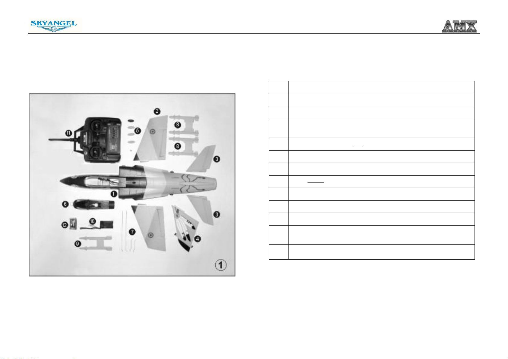
Parts List
NO.
Description
1
Fuselage
2
Wing Set – One Left (and one Right) Wing Panel
3
Tail Set - One Left (and one Right) Horizontal Stabilizer with
Elevator
4
Tail Set - One Vertical Fin Stabilizer
5
Landing Skids
6
Cockpit Canopy
7
Steel Wires Push Rods Set
8
Big Missiles
9
Small Missiles
10
850mAh 11.1 Volt 20C Li-Po Battery
11
Radio Control Transmitter (we highly recommend 2.4 GHz
system)
12
Charger
Fig. 1 Open the box and check all the parts.
Assembly and Operating Manual
Parts Illustration
3
Page 4
Assembly and Operating Manual
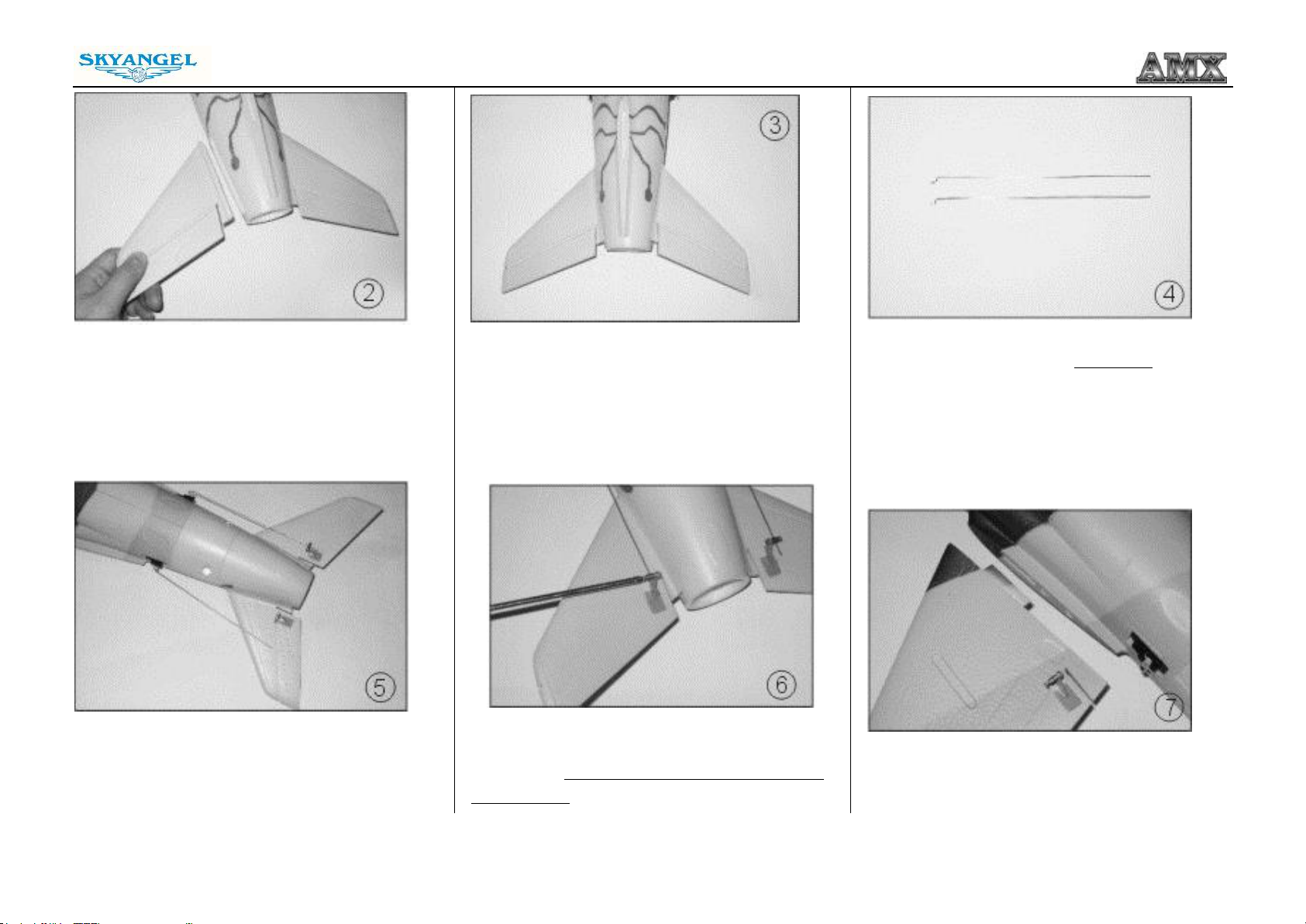
Fig. 2 - Glue the horizontal tail wings
at the rear of the fuselage (glue not included).
Fig. 5 - Connect the push rods to the elevator
control horns.
into the slots
Fig. 3 - Remove any excess glue and hold in
position until glue sets. The photo shows the
finished view.
.
Fig. 6 - Tight the set screws on the elevator EZ
connectors . elevator steel wire with cross screw
and trim lever.
Fig. 4 - Locate the elevator steel wires push rods
set.
Fig. 7 - Apply glue to the sides of each main wing
panel (glue not included).
4
Page 5
Assembly and Operating Manual
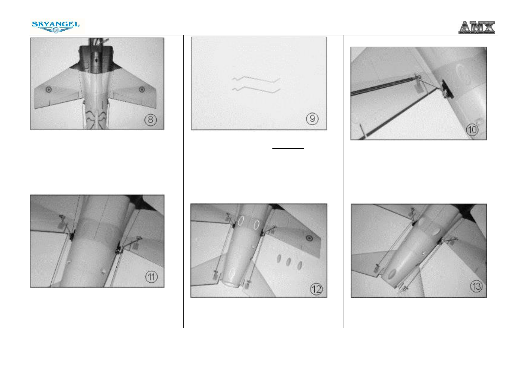
slot)
Fig. 8 - The photo shows the finished view after
gluing the wings in place.
Fig. 11 - Photo shows the finished view after all
steel wires assembled.
Fig. 9 - Locate the aileron steel wires
push rods
set.
Fig. 12 – Locate the landing skids and apply glue
to the back of the fuselage. (white mark shows the
Fig. 10 - Connect the push rods to the aileron
servo arm and trim lever
control horns.
Fig. 13 - Photo shows the finished view after
are assembled.
skids
the
5
Page 6
Assembly and Operating Manual
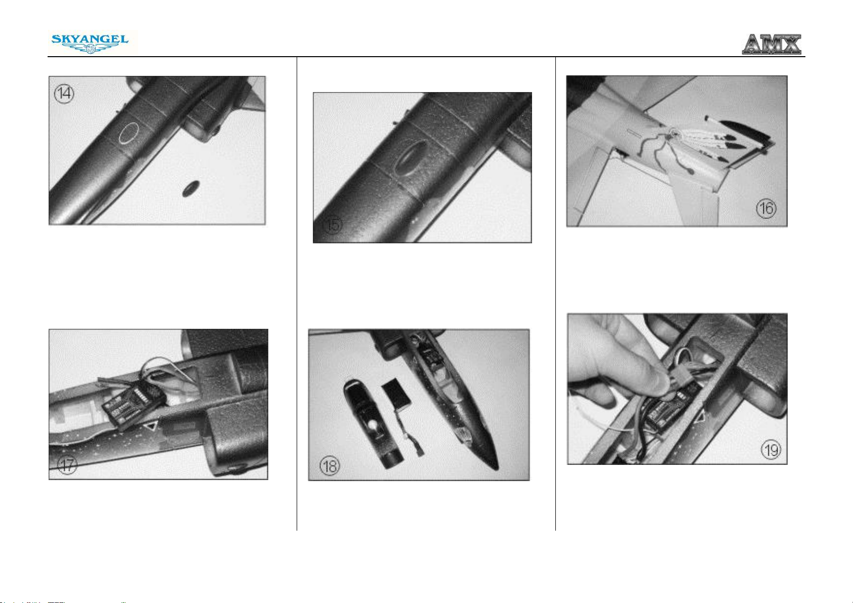
manualstructions for the correct channel sockets
and servo lead polarity.
before installing.
Fig. 14 - Locate the
blue landing skid and apply
glue to the front of the fuselage. (white mark
shows the slot)
Fig. 17 - Connect the electronic speed controller
and servos to the receiver. Refer to the radio
Fig. 15 - Photo shows the finished view after the
skid
is assembled.
Fig. 18 - Locate the battery and canopy. Charge
the battery according to the safety instructions
Fig. 16 - Glue the vertical fin sections as shown in
the photo (glue not included).
Fig. 19 - Photo shows battery leads shown
connected to the electronic speed controller.
6
Page 7
Assembly and Operating Manual
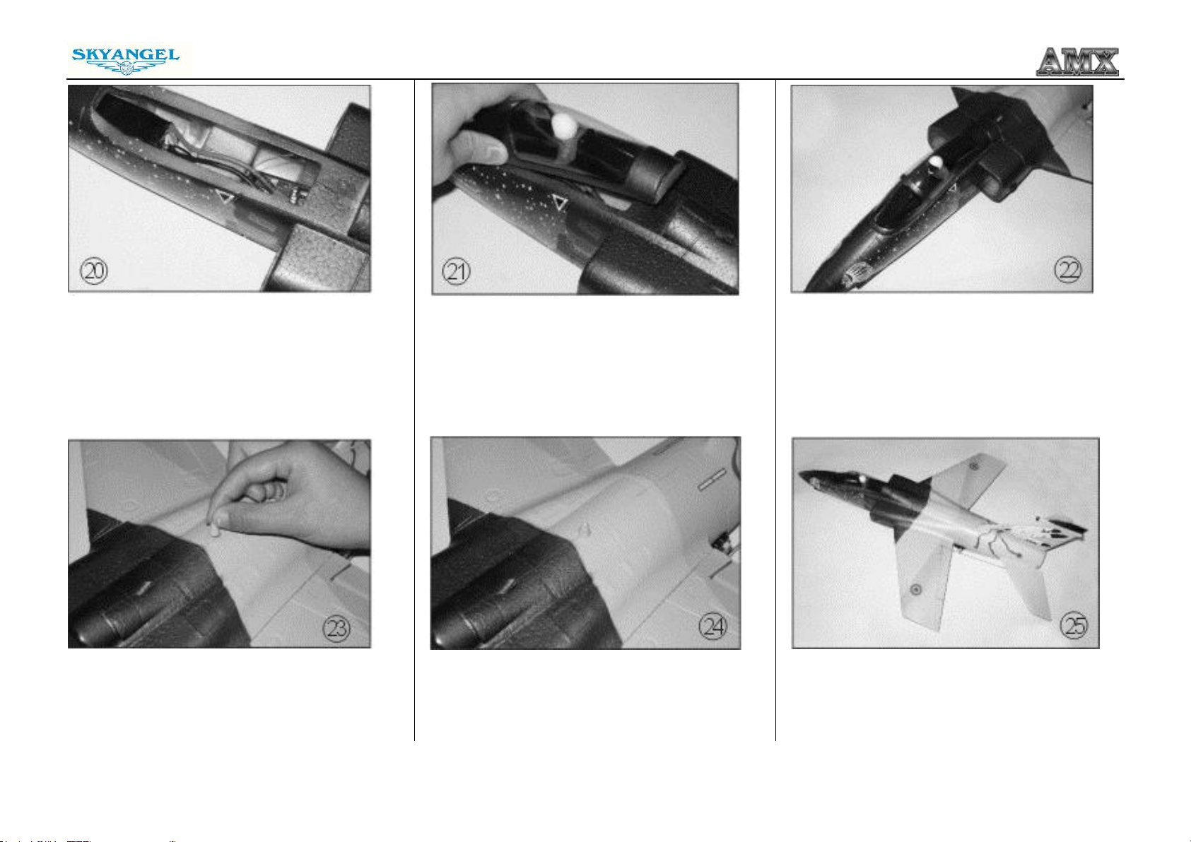
Fig. 20 - Insert the battery into the front of the
fuselage.
Fig. 23 – Locate the decoration and apply glue to
the fuselage.
Fig. 21 - The canopy is held in place by magnets
and can be lifted off.
Fig. 24 - Photo shows the finished view after
decoration assembled.
Fig. 22 - Photo shows the finished view after
canopy assembled.
Fig. 25 - Congratulations, you have completed
the assembly process. We hope you enjoy
flying your new model!
7
Page 8
Optional parts (not required)
Assembly and Operating Manual
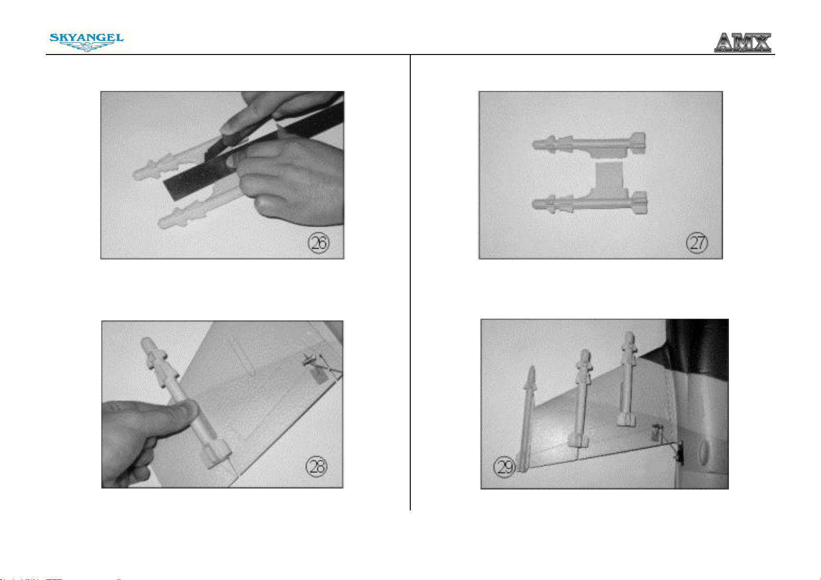
Fig. 26 – Three sets of 3 painted missiles, for extra realism, are included.
Cut apart for assembly as shown
Fig. 28 - Glue missiles according to the main wing slots (glue not included).
8
Fig. 27 - Missiles shown after being separated.
Fig. 29 - Photo shows missiles in attached position.
Page 9
Assembly and Operating Manual
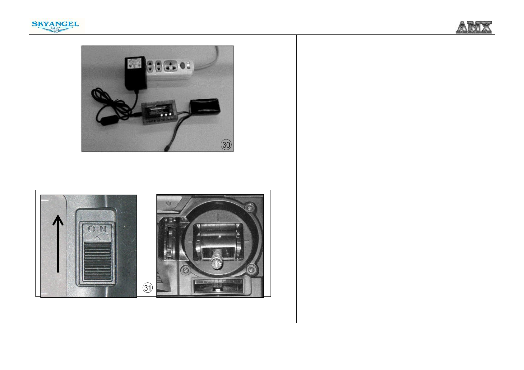
Fig. 30 - Charge the flight battery; connect the Equalizer lead
using and adapter lead matching your charger (adapter lead not
included).
Fig. 31 - Switch the transmitter on, and move the throttle stick to
the “Motor OFF” position.
- Remove any loose objects such as cloths, tools or similar from
the area in front of the model, as they could easily be sucked
into the ducted fan.
- Open the throttle (stick forward): the motor should now run,
and you should feel a strong flow of air exiting the tail end of
the model.
- Move
.
9
Page 10
Assembly and Operating Manual
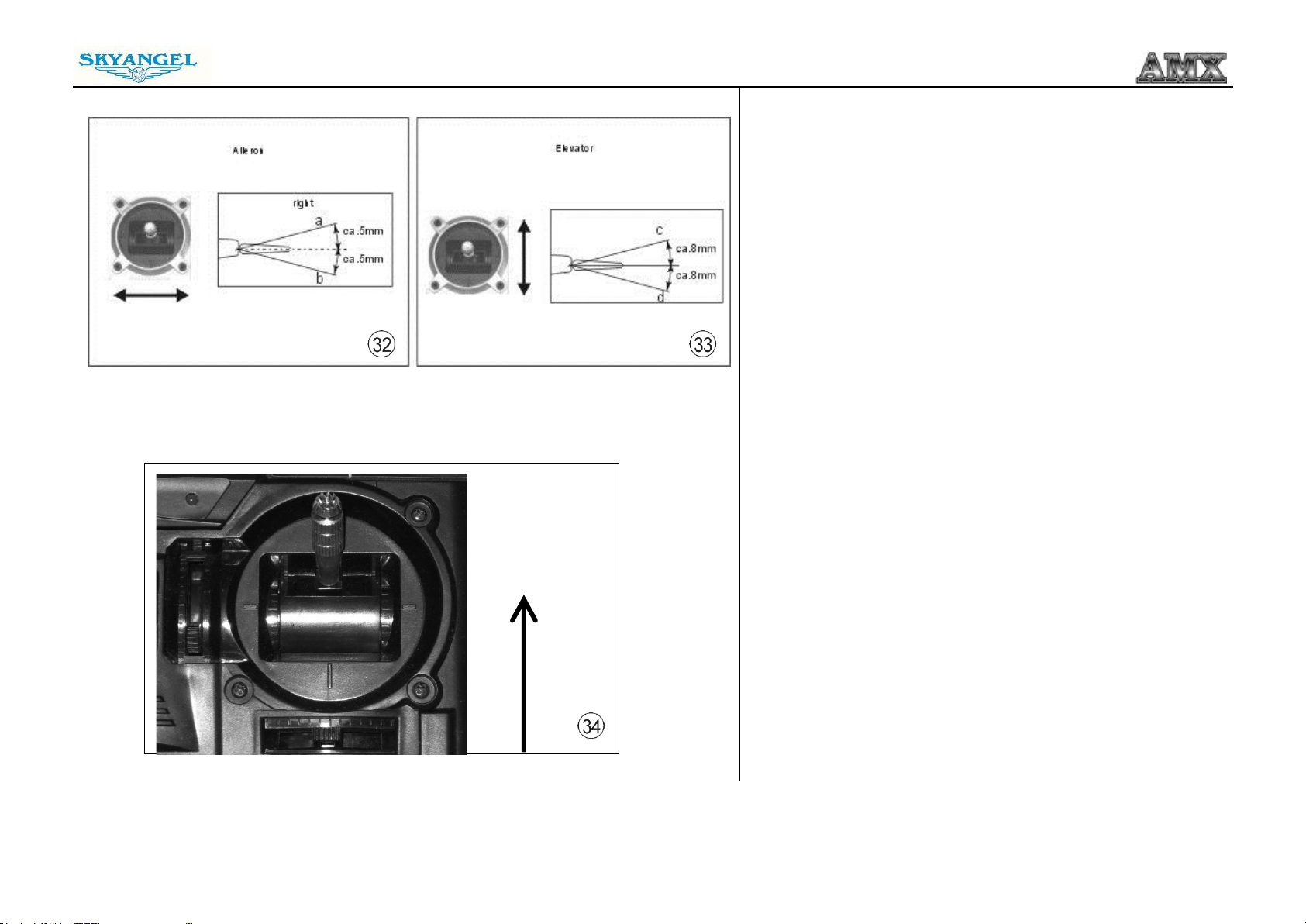
Fig. 32 and 33 - Checking Ailerons and Elevators
- Check that the control surfaces respond to the appropriate
movements of the transmitter sticks. If not, swap over the
connectors at the receiver.
- Check the neutral position of the control surfaces; you may
need to screw the clevises in or out to correct any discrepancy.
- Stand behind the model.
- Check the direction of rotation of the servos:
- Move the aileron stick to the right (a), and the right aileron (a)
must rise up, the left aileron (b) fall down.
- Pull the elevator stick back towards you (c), and the
trailing edge of both elevators should rise (c).
- If either function works in the wrong way, correct it using your
transmitter’s servo reverse facility for that channel.
Fig. 34 - Checking the power system
- Hold the model securely.
- Remove any loose objects such as cloths, tools, etc from the
area in front of the model, as they could easily be sucked into
the ducted fan.
- Open the throttle (stick forward): the motor should now run,
and you should feel a strong air flow rushing out from the tail
end of the model.
- Move the throttle stick back to the “Motor OFF” position.
- Disconnect the battery from the electronic speed controller and
then switch the transmitter off.
10
Page 11
Assembly and Operating Manual
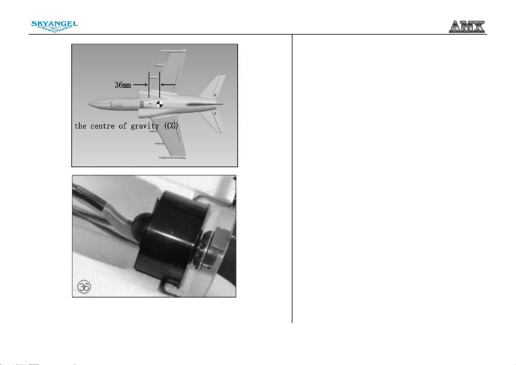
Fig. 35 - Checking the model’s balance
- Place the flight battery in its compartment, without connecting.
- Mark the Centre of Gravity (CG) on both sides of the fuselage;
the position is shown in the photo.
- Support the model at the marked points and allow it to hang
freely. When correctly balanced the airplane will remain
horizontal, with the nose slightly down.
- If necessary, adjust the position of the flight battery to achieve
the correct CG.
- Mark the battery location in the fuselage, so that you can be
sure of positioning it correctly after recharging.
- Pack scrap pieces of foam around the battery in its final
position, otherwise there is a danger of it shifting in flight and
altering the model’s balance.
- Charge the flight battery and the model is ready for flight.
Fig. 36 - Access to the ducted fan unit and electronic speed
controller
- The ducted fan unit is accessible from underneath, if you need
to carry out maintenance work or repairs.
- Ensure that the wire colors match correctly.
11
Page 12
Test Flying - Notes on flying the airplane
Please read the sections entitled “Routine pre-flight checks” and “Flying
the model” in the Safety Notes before attempting to fly the AMX Jet for
the first time.
- For the first flight you should wait for a relatively calm day with no more
than a gentle breeze.
- A good flying site is a large, flat, open field; well away from trees, fences,
high-tension overhead cables and other potentially dangerous obstacles.
- Carry out a complete check of the working systems.
- We recommend that you ask an experienced modeler to help you initially;
to give the model a fairly powerful hand-launch.
- The model must be launched directly into any existing wind.
- Switch the motor on, and launch the airplane strongly into the wind, with the
fuselage and wings level.
- Allow the AMX Jet to fly straight and level initially; don’t try to turn it when it
is close to the ground.
- Adjust the trims if necessary so that the model settles into a steady climb.
- Check the model’s response to control commands from the transmitter. You
may need to increase or reduce the control surface travels once the model
is back on the ground.
- Take the airplane up to a safe height and check its stalling speed.
- Keep the speed well up on the landing approach to avoid stalling.
- If you had to move the trims during the flight, correct the mechanical
linkages before flying again. This allows you to re-centre the trims, so that
full trim travel is available for subsequent flights.
- We reserve the right to introduce technical modifications and suggest that
you check our website for updates.
Jiangyin Skyangel Electronic Technology Co., Limited.
No.606 Zhencheng Road,Xiagang Town,
Jiangyin city, Jiangsu Province, 214400, China
Tel / Fax: +86-0510-86168833
www.jpower.hk
12
 Loading...