

Page 1
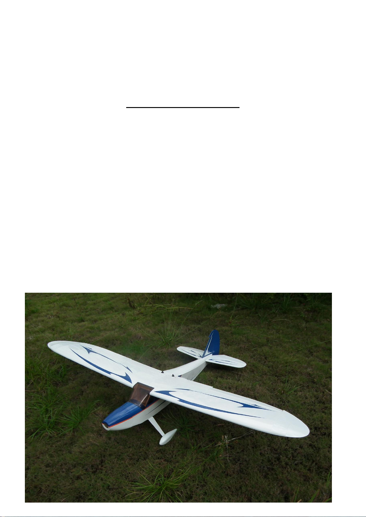
Little Apple-A4 -50E
Specifications
Wingspan: ......................................................... 1766mm (69.5 in)
Length: ............................................................ 1290mm (50.8 in)
Wing Area: ................................................ 45.3 sq dm (702.8 sq in)
Weight: ................................................... 2.5–3.0kg (5.5–6.5 lb)
Radio: ........................................................4-channel w/4–5 servos
Engine: ...................... .40–52 2-stroke; .56–82 4-stroke; Power 46
ARF
ASSEMBLY MANUAL
The new Little Apple-A4-50E ARF, was designed in an extremely
lightweight structure, the all wood airframe with refreshing colors cover.
High-wing design is easy to fly for the beginner. This is the electric
motor assembly manual, but we still provide the engine mount and the
fuel tank spare parts. In case when you became a good player you can
change to the methanol engine power.
The Little Apple-A4-50E will bring you the flying sky, if you want to
fly and just do it.
.....without any aerobatic limit when you fantasy to do it !
1
Page 2

Table of contents
Table of contents...............................................................................................................……….. 2
Required radio, motor and battery.............................................................................................…. 3
Additional required items, tools and adhesives.............................................................................. 3
Warning.......................................................................................................................................... 3
Before starting assembly ...........................................................................................................… 3
Using the manual........................................................................................................................... 4
Section 1 – ailerons installation...................................................................................................... 5
Section 2 – aileron servo & control horn installation…............................................................…. 6
Section 3 –elevator installation ………..…................................................................................... 8
Section 4 –rudder installation & tail wheel installation................................................................. 10
Section 5 – elevator servo & control horn installation................................................................... 12
Section 6 – rudder servo & control horn installation…………………………………………….. 16
Section 7 – landing gear & wheels installation…………………………………….…………….. 19
Section 8 – electric motor installation …..…..…………................................................................21
Section9 – electronic speed controller and his switch and battery installation................................23
Section 10 – cowl installation…..…..…………..............................................................................24
Section 11 – final radio installation………….................................................................................25
Section 12 – window installation………….....................................................................................25
Section 13 – wings installation………….........................................................................................26
Control throws................................................................................................................................ 27
Rates and expos..........................................................................................................................…. 27
Center of Gravity(CG)...............................................................................................................…. 27
Range test your radio..................................................................................................................…. 28
Age requirements.......................................................................................................................…. 28
Safety, Precautions and Warnings.............................................................................................…. 28
2
Page 3

Required radio, motor and battery
Radio equipment:
• DX6i 6-channel radio or greater with receiver(SPM6600)
• JRPS821 DS821 Digital Sport Servo (5)(4 required for EP version)
• JSP98110 6-inch Servo Extension (2)
• JSP98020 Y-Harness or JSP98110 6-inch Servo
Extension (2) for receiver to aileron servos
• JR Switch, Charges witch (JRPA004)
• Receiver battery, 2700mAh
Recommended electric motor for best performance:
• E-flite® Power 46 BL Outrunner Motor (EFLM4046A)
• 60-Amp Pro Switch-Mode BEC Brushless ESC (EFLA1060)
• Thunder Power 4S 3850–4500mAh LiPo Battery Pack
• APC Propeller 13x6.5-inch (APC13065E) to14x7 (APC14070E)
Additional required item, tools and adhesives
Tools:
Drill
Drill bits: 1,5mm, 2mm, 3mm, 5.3mm
Phillips screwdriver
Hobby knife
Sanding paper
Masking tape
Soldering iron
Socket head screw wrench:1.5mm 2.5mm 3mm
Adhesives:
thin CA
medium CA
30min Epoxy adhesive(AB)
Warning
This RC aircraft is not a toy!
If misused, it can cause serious bodily harm and damage to property
Fly only in open areas, preferably in official flying sites, following all instructions included with
your radio and motor
Before starting assembly
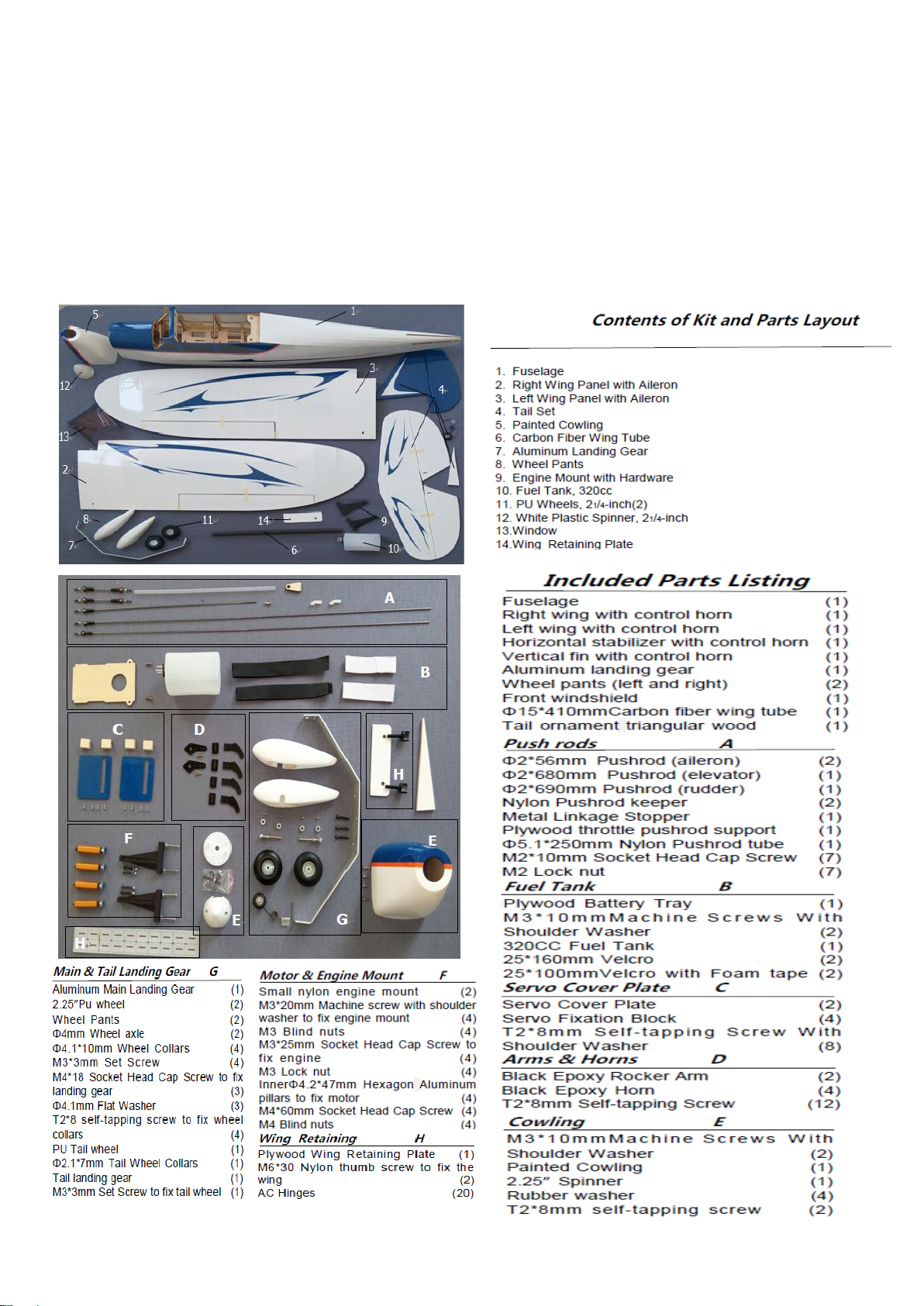
Before starting the assembly of your Little Apple-A4-50E, remove each part from its bag and protection for
a prior inspection Closely inspect the fuselage, wing panels, rudder, and stabilizer for damage. If you find
any damage or missing parts, contact the place of purchase. If you find any wrinkles in the covering, use a
heat gun or covering iron to remove them. Use caution while working around areas where the covering
material overlap to prevent separating the covers.
3
Page 4
Using the manual
This manual is divided into sections to help make assembly easier to understand and to
provide breaks between each major section.
In addition, check boxes(□) have been placed next to each step to keep track of each step
completed. Steps with two boxes(□□) indicate that the step will require repeating, such as
for a right or left wing panel, two servos, etc.
Remember to take your time and follow the directions.
4
Page 5
Section 1 – ailerons installation
Required Parts
Main Wing (Right & Left)
Aileron(Right & Left)
Eight Hinges (Right & Left)
Tools and Adhesives
Hobby knife
Thin CA
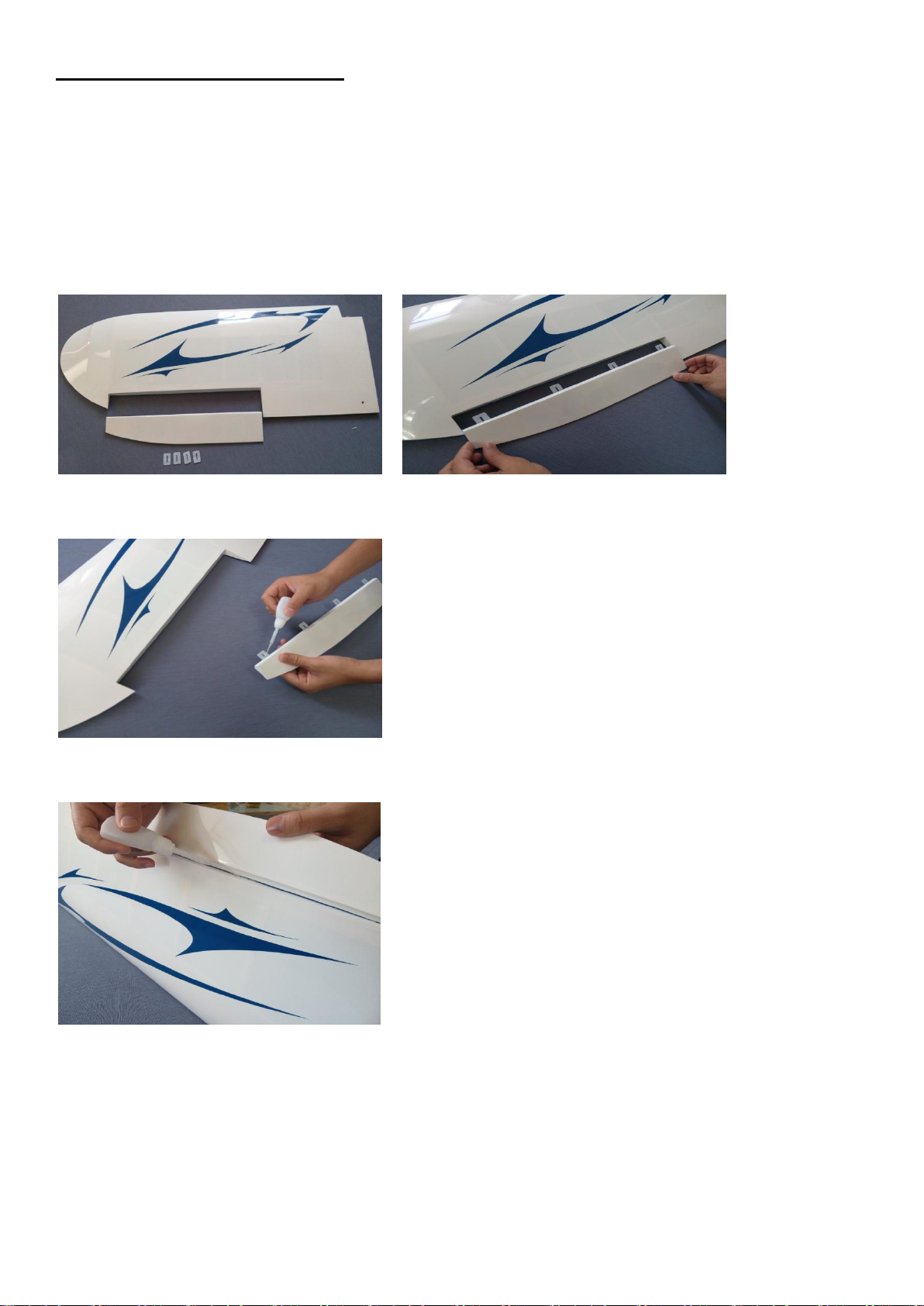
□□step 1
Trial fit the four aileron hinges, included in the hardware pack, in their place and verify the correct
position and alignment of the aileron with the wing panel.
□□step 2
Carefully glue, with some drops of thin CA, each of the four hinges in the aileron.
□□step 3
Locate the aileron and carefully glue, with some drops of thin CA, the hinges into the wing panel.
□□step 4
Work the aileron up and down some times to work the hinges and check for proper movement.
□step 5
Repeat steps 1 through 4 for the remaining wing panel.
5
Page 6
Section 2 – aileron servo & control horn installation
Required Parts
2 Servo Cover Plate (Right & Left)
4 Servo Fixation Block (Right & Left)
8 T2*8mm Self-tapping Screw With Shoulder Washer (Right & Left)
2 Black Epoxy Rocker Arm (Right & Left)
2 Black Epoxy Horn and pedestal (Right & Left)
2 Φ2*56mm Pushrod (aileron) (Right & Left)
4 Bolt Through Ball (Right & Left)
4 M2*10mm Socket Head Cap Screw (Right & Left)
4 M2 Lock nu (Right & Left)
2 Servo with hardware (Need to buy)
Tools and Adhesives
Hobby knife Phillips screwdriver Drill and drill bits 1.5mm
Thin CA Socket head screw wrench 1.5mm
Right and left are the same
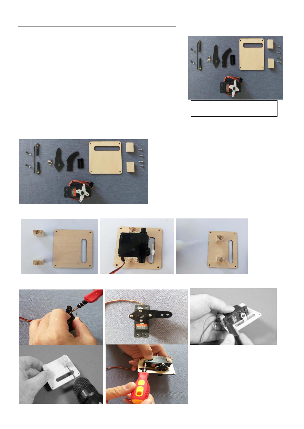
□□step 1
Locate the following items included in the hardware pack and the servo.
□□step 2
Test the best position of the servo wood block, and glue it on the plywood as per picture showed.
□□step 3
Pre-install the rock-arm and the servo with theT2*8mm self-tapping screw as per picture.
6
Page 7
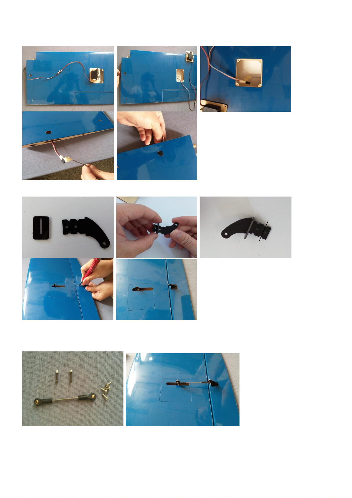
Cut off 1/3 and paint
some mixing 30min
epoxy around on the
horn
□□step 4
Put the pre-installation servo into the wing panel,as per picture.
□□step 5
Glue the epoxy horn with medium CA into the aileron, as per picture.
□□step6
Install the push and pull rod connecting rod,and use the four T2*8mm Self-tapping Screw With Shoulder Washer
to fix the servo cover plate.
□step 7
Repeat steps 1 through 6 for the remaining wing panel.
7
Page 8
Required Parts
1 horizontal tai 1 Elevator 6 Hinges 1 Elevator connect steel wire
Tools and Adhesives
Hobby knife Thin CA Straight Steel Ruler
Remark pen Hobby knife
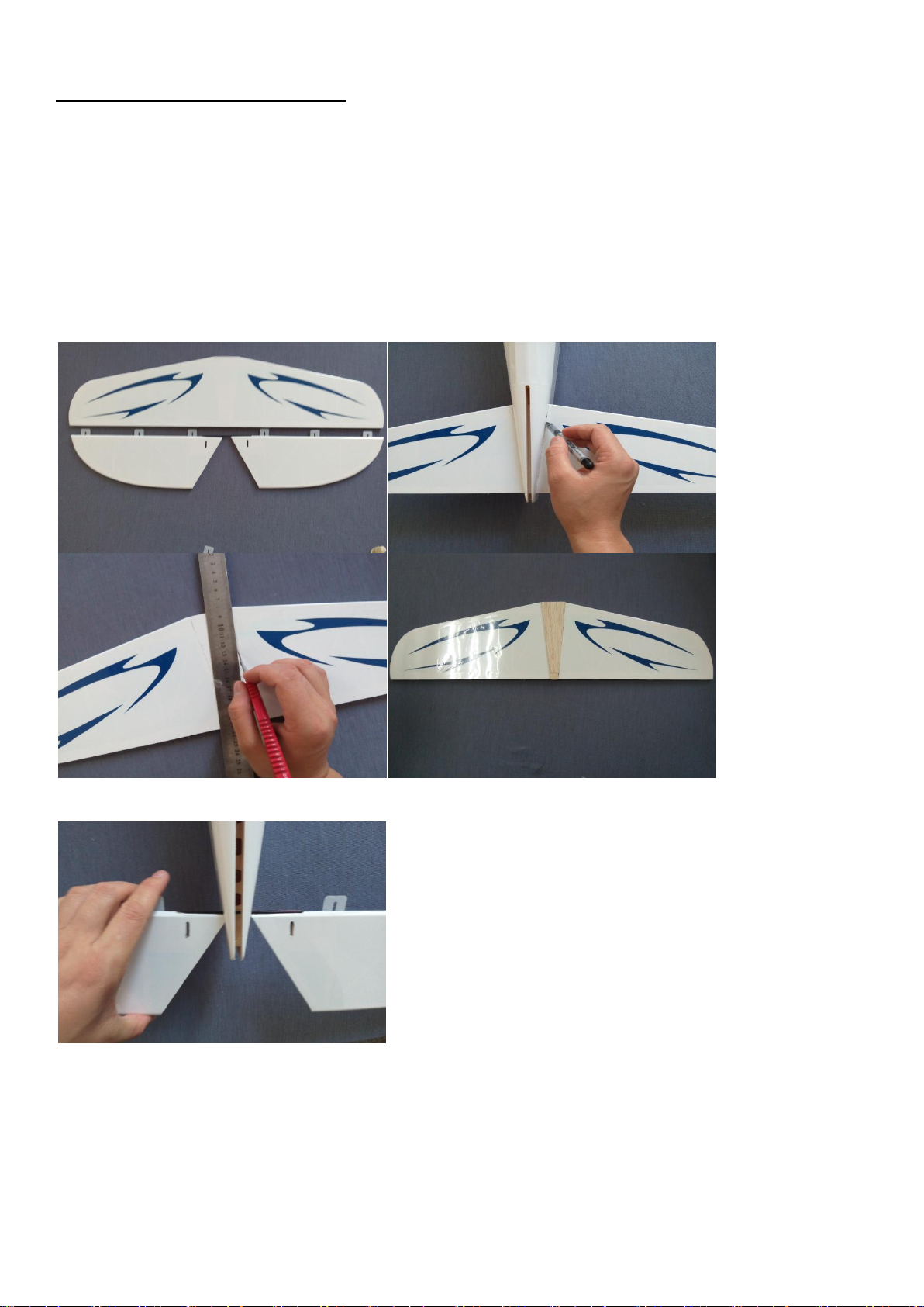
Section 3 – elevator installation
□step 1
Insert in the elevator the four hinges into their appropriate slots and verify the correct position and
alignment of the elevator with the stabilizer. Than put the horizontal tail into the fuselage tail and make
remark. Take out the horizontal tail and use a hobby knife to detruncate some covering. As per picture
shown.
□step 2
Insert the elevator through the fuselage
□step 3
Insert the horizontal tail into fuselage space and locate the elevator hinges into the horizontal tail
8
Page 9
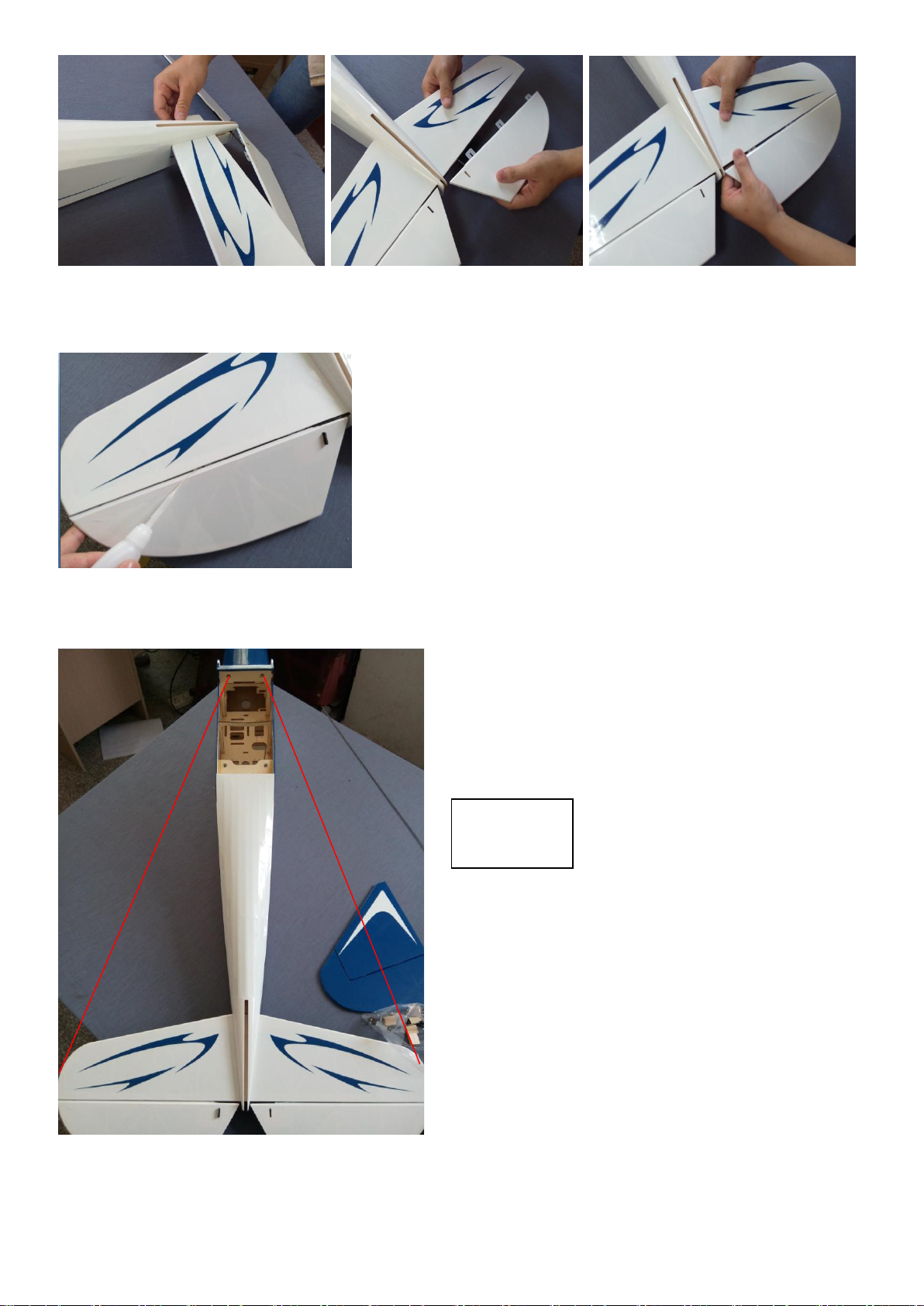
A
A”
A=A”
□□step 4
Glue carefully the hinges in the horizontal tail and elevator with some drops of thin CA.
□step 5
Carefully check the balance of the horizontal tail with the fuselage, as per pictures.
□step 6
9
Page 10
Once satisfied with the balance, glue carefully with thin CA the horizontal tail at the fuselage.
Required Parts
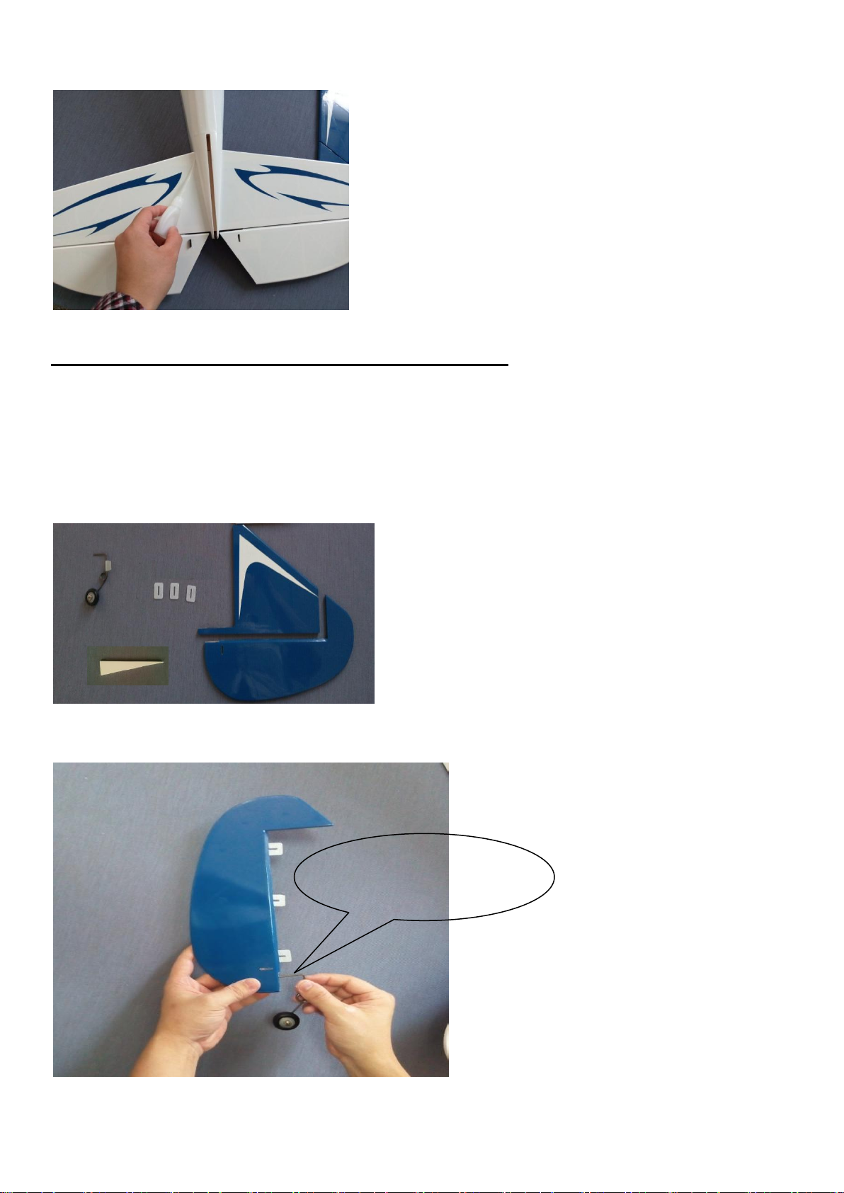
1 Rudder 1 Vertical fin 3 Hinges 1 Set tail wheel system 1triangular lightwood block
Tools and Adhesives
Hobby knife Thin CA Straight Steel Ruler
Marking pen Hobby knife 30min Epoxy
Paint some 30min epoxy
around the steel wire
Section4 – rudder installation & tail wheel installation
□step 1
Locate the items included in the hardware pack.
□step 2
Inset three hinges into the rudder ,than install the tail wheel system, as picture shown.
□step 3
10
Page 11
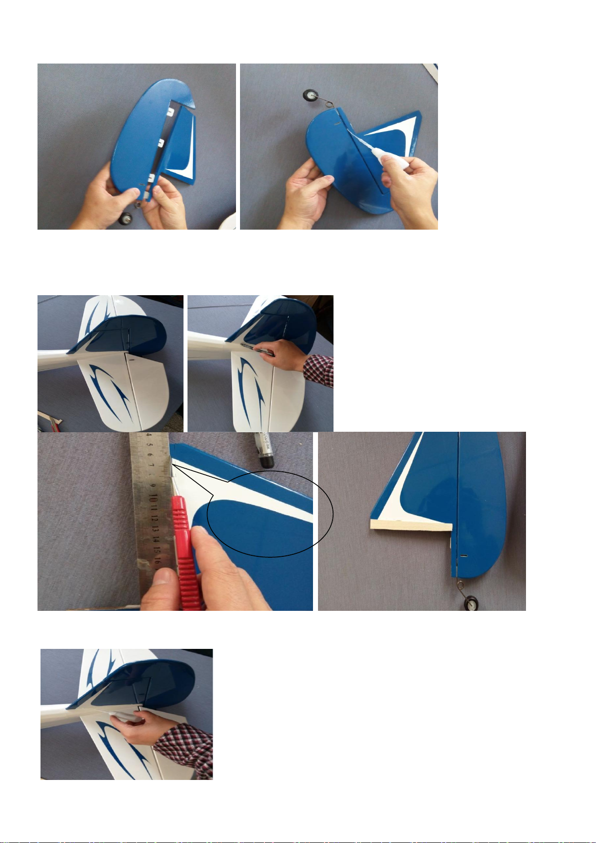
Install the rudder to the vertical fin, and glue each hinges with thin CA.
Keep 2-3mm
far away from
the marking
line
□□step 4
Inset the assembled rudder to the vertical fin into the fuselage, and make a remark on the cover. Than take
out the vertical fin and use a knife to chip-off some cover, as per picture shown.
□step 5
Insert the pretreatment vertical fin and rudder into the fuselage and glue it with thin CA, as picture shown.
11
Page 12
□step 6
690mm
Required Parts
1 Φ2*690mm Pushrod (elevator) 1 Nylon Pushrod keeper
1 M2*10mm Socket Head Cap Screw 1 M2 Lock nut 1 Black Epoxy Horn with pedestal
1 Nylon ball joint
Tools and Adhesives
Socket head screw wrench 1.5mm Pliers 30min Epoxy Phillips screwdriver
Adhesive-Paper
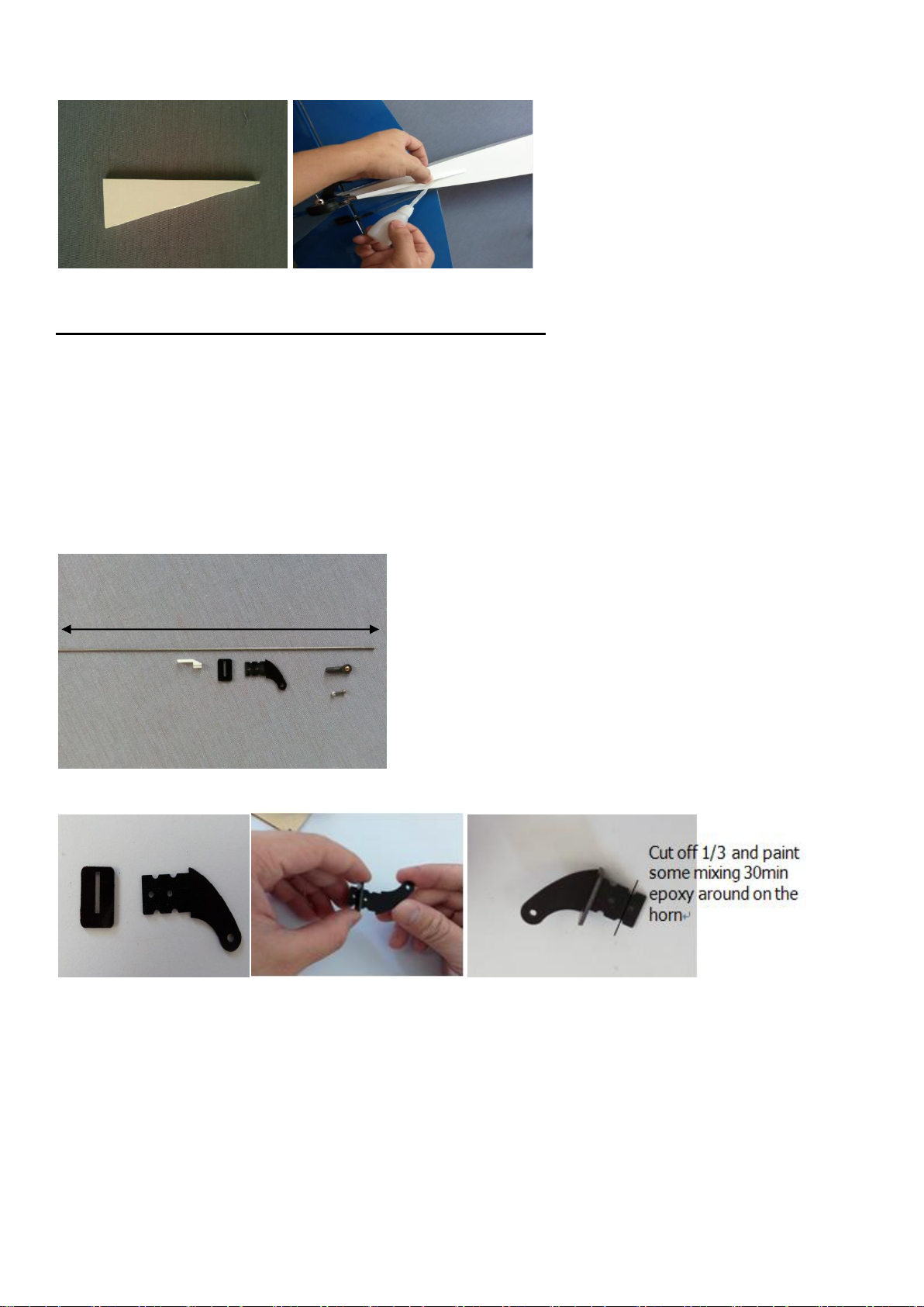
Bottom up the fuselage and fix the triangular lightwood block to the vertical fin, as the picture shown.
Section 5 – elevator servo & control horn installation
□step 1
Locate the following items included in the hardware pack.
□step 2
Install the horn as per picture.
□step 3
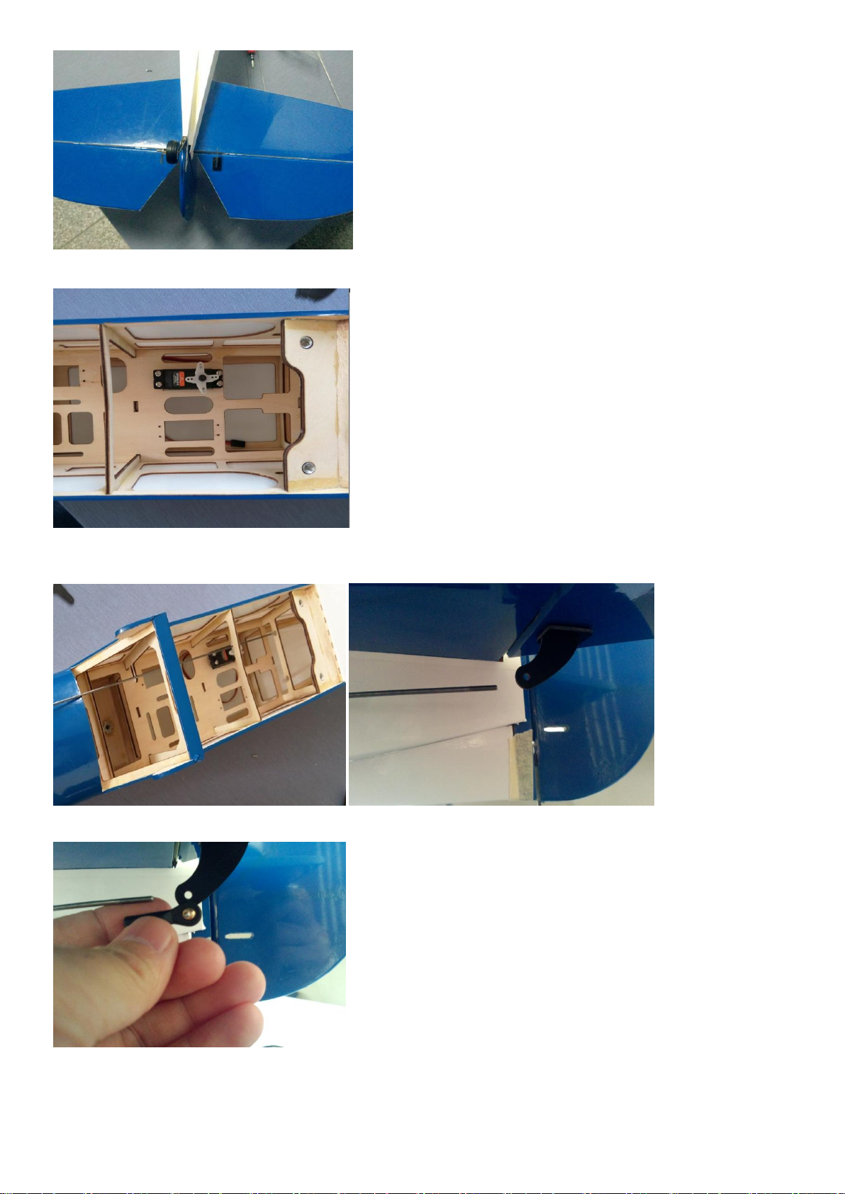
Up side down the fuselage and install the horn into the right elevator(front under the left elevator), as the
picture shown.
12
Page 13
□step 4
Install the elevator servo in the fuselage,as the picture shown.
□step 5
Put elevator push rod(with screw thread side) through the elevator Pushrod tube hole, reach the elevator horn
position ,as picture shown.
□step 6
Use the nylon ball joint to proofread the distance between the rudder push rod and the horn, as picture shown.
□step7
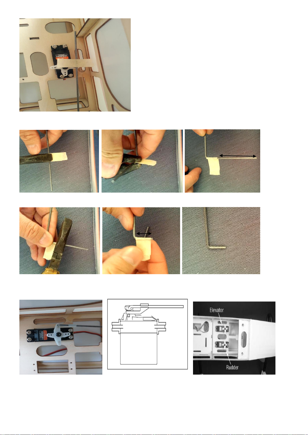
Calculate the push rod length in need, than make a remark on the servo side, as picture shown.
13
Page 14
7-8mm
cut
□step 8
Take out the elevator push rod and use a pliers to bend the push rod to 90°,as the picture shown.
□step 9
Cut the redundant length of the push rod, as the picture shown.
□step 10
Install the elevator push rod into the push rod tube again, and use the Nylon Pushrod keeper to lock the push
rod in the elevator horn.
□step 11
Up side down the fuselage and install the ball joint to the elevator push rod and the elevator, as the picture
shown.
14
Page 15
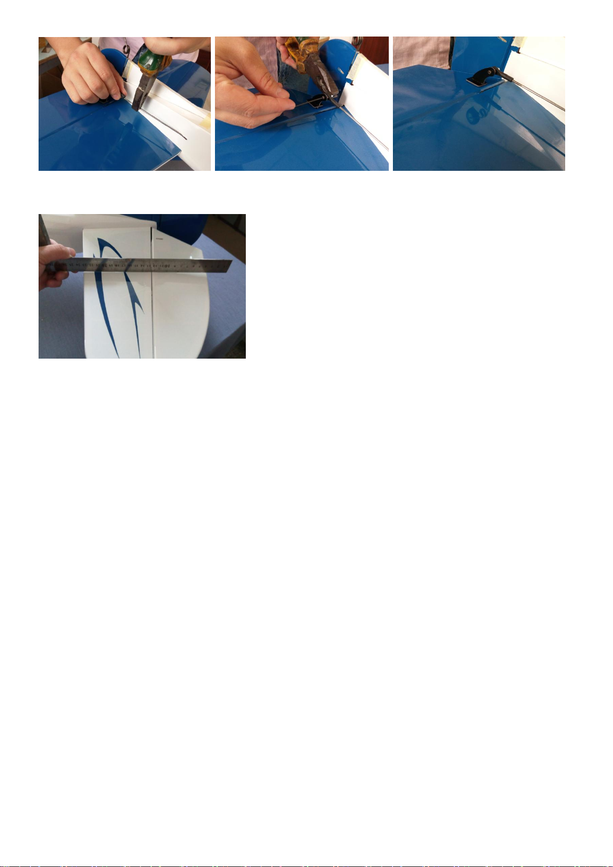
□step 12
Keep the horizontal tail and the elevator in a level.
15
Page 16
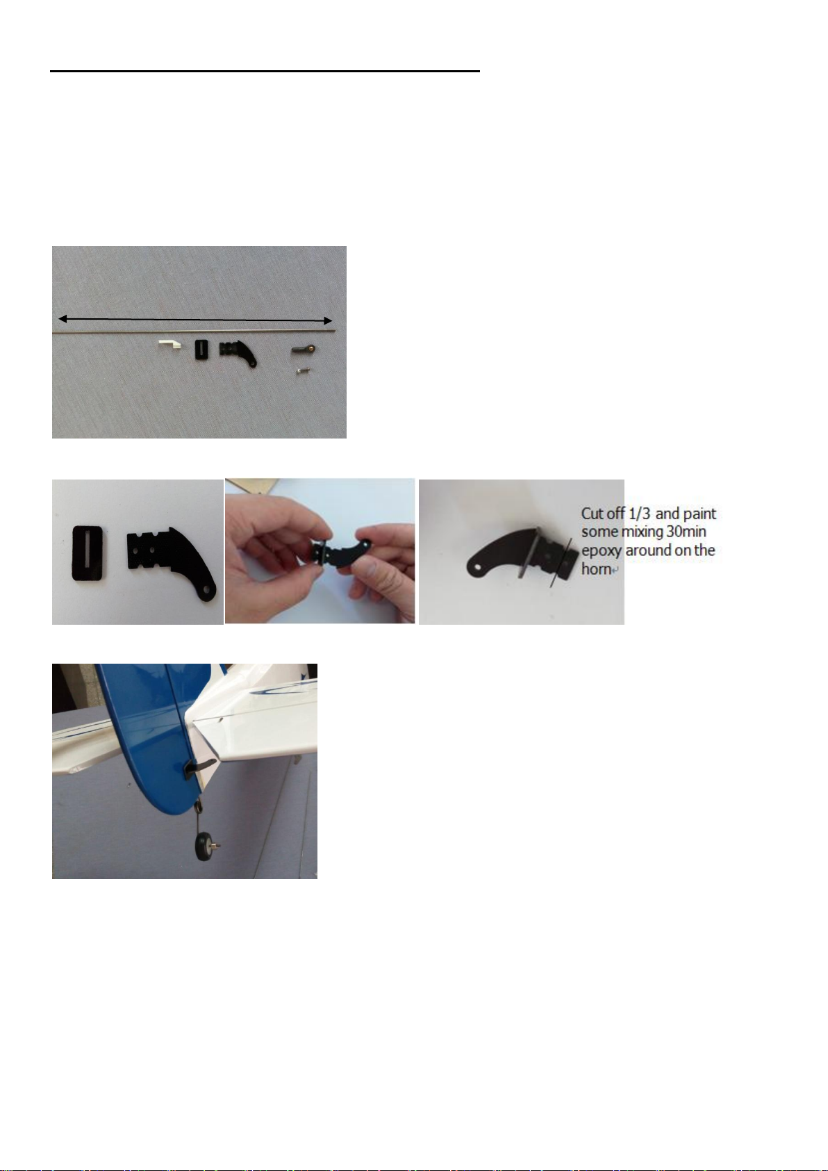
Section 6 – rudder servo & control horn installation
690mm
Required Parts
1 Φ2*690mm Pushrod (elevator) 1 Nylon Pushrod keeper
1 M2*10mm Socket Head Cap Screw 1 M2 Lock nut 1 Black Epoxy Horn with pedestal
1 Nylon ball joint
Tools and Adhesives
Socket head screw wrench 1.5mm Pliers 30min Epoxy Phillips screwdriver
Adhesive-Paper
□step 1
Locate the following items included in the hardware pack.
□step 2
Install the horn as per picture.
□step 3
Install the horn into the right rudder right side, as the picture shown.
□step 4
Install the rudder servo in the fuselage,as the picture shown.
16
Page 17
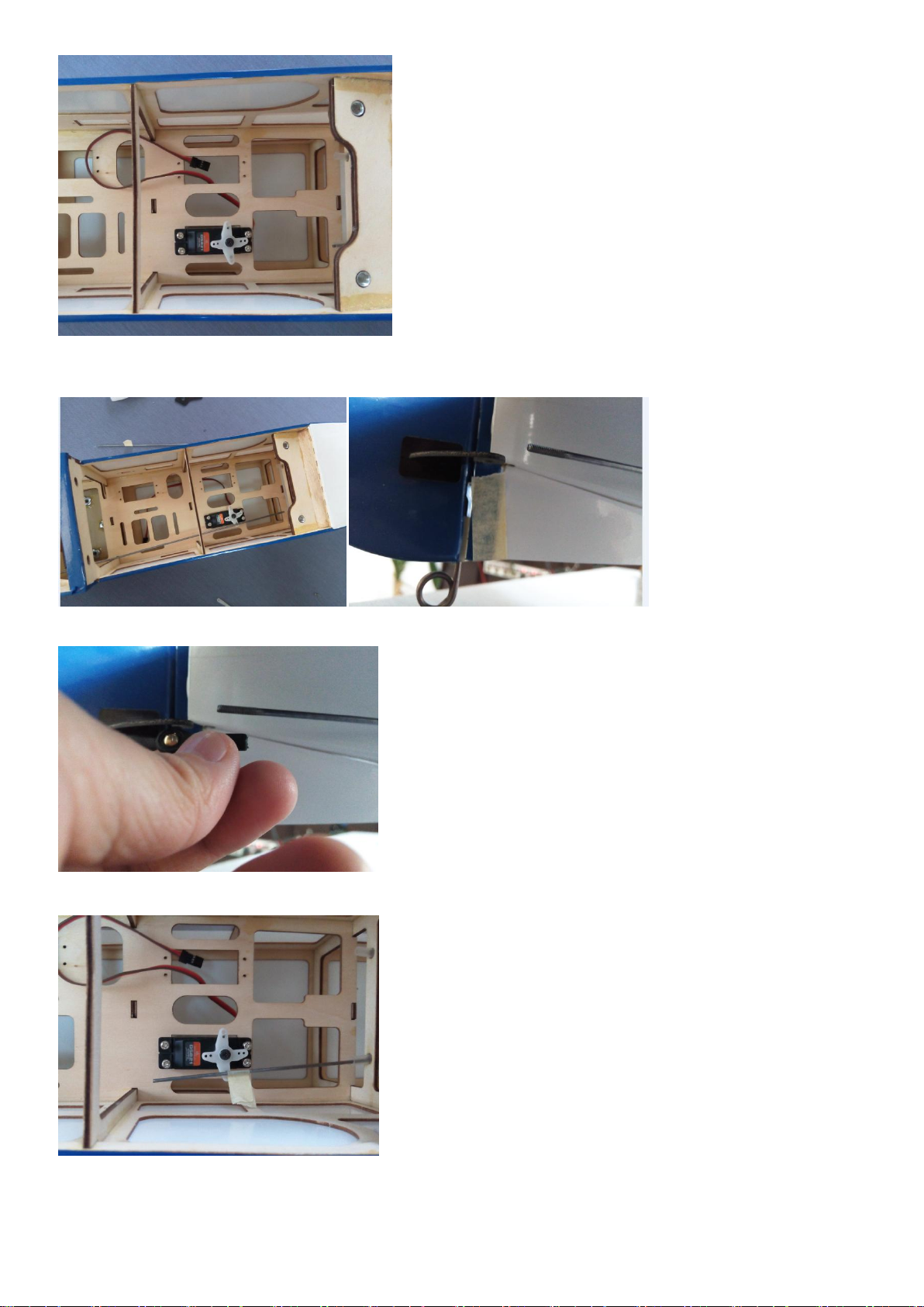
□step 5
Put rudder push rod(with screw thread side) through the rudder pushrod tube hole, reach the rudder horn
position ,as picture shown.
□step 6
Use the nylon ball joint to proofread the distance between the rudder push rod and the horn, as picture shown.
□step7
Calculate the push rod length in need, than make a remark on the servo side, as picture shown.
□step 8
Take out the rudder push rod and use a pliers to bend the push rod to 90°,as the picture shown.
17
Page 18
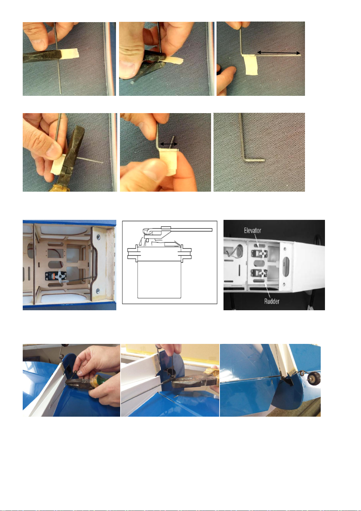
7-8mm
cut
□step 9
Cut the redundant length of the push rod, as the picture shown.
□step 10
Install the rudder push rod into the push rod tube again, and use the Nylon Pushrod keeper to lock the push
rod in the rudder servo horn.
□step 11
Up side down the fuselage and install the ball joint to the rudder push rod and the rudder horn, as the picture
shown.
18
Page 19
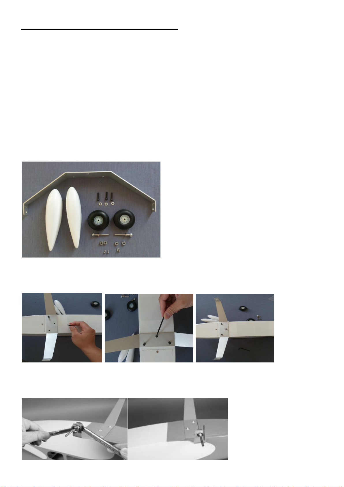
Section 7 – landing gear & wheels installation
Required Parts
1 Aluminum Main Landing Gear
2 2.25”Pu wheel
2 Wheel Pants
2 Φ4mm Wheel axle
4 Φ4.1*10mm Wheel Collars
4 M3*3mm Set Screw
3 M4*18 Socket Head Cap Screw
3 Φ4.1mm Flat Washer
4 T2*8 self-tapping screw with washer
Tools and Adhesives
Phillips screwdriver Drill and drill bits 1.5mm Threadlock
Socket head screw wrench 1.5mm
Box wrench: 7/16-inch, 1/2-inch
Hex wrench or ball driver:1.5mm 3mm
□step 1
Locate the following items included in the hardware pack.
□step 2
The main landing gear is mounted to the bottom of the fuselage using three M4*18 Socket Head Cap Screw
and threeΦ4.1mm Flat Washer. Apply a drop of threadlock on each of the screws. Use a 3mm hex wrench to
tighten the screws to secure the landing gear to the bottom of the fuselage.
□□step 3
Attach the wheel axle to the landing gear using a 7/16-inch box wrench (axle) and 1/2-inch box wrench (nut).
Make sure the nut on the axle side aligns with the landing gear as shown in the photo so the wheel pant can
be installed.
19
Page 20
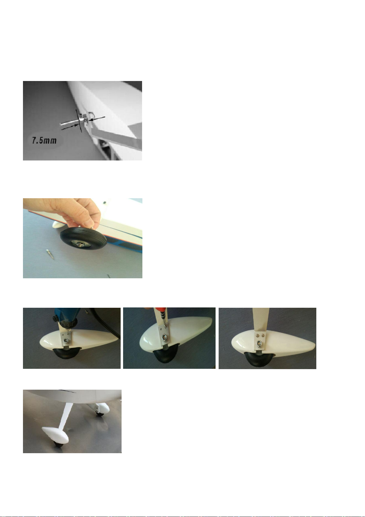
□□step 4
Attach a Φ4.1*10mm Wheel Collars to the axle using a 3mm x 5mm set screw. Make sure to apply
threadlock to the screw so it will not vibrate loose. Position the collar so it is 7.5mm from the landing gear
as shown and use a #2 Phillips screwdriver to tighten the screw on the flat area of the axle. The position of
the wheel may need to be fine-tuned in the last step of this section.
□□step 5
Slide the wheel on the axle. Use a 5/32-inch wheel collar and a 3mm x 5mm machine screw to secure the
collar. Make sure to position the collar so the wheel can rotate freely on the axle. Use a #2 Phillips
screwdriver to tighten the screw on the flat area of the axle.
□□step 6
Use a 1.5mm drill bit to drill two holes on the wheel pant, and then use Phillips screwdriver to drive the 2
T2*8mm self-tapping screw with washer in to the pant to retaining it.
□step 7
Repeat steps 3 to 6 for the other side of the landing gear.
20
Page 21
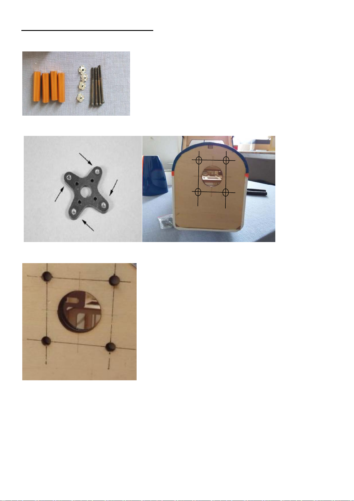
Section 8 – electric motor installation
□step 1
Find the parts in the hardware pack.
□step 2
According the motor size to draw the holes position on the fire wall, as the picture shown.
□step 3
Us a 5.5mm drill bit to dill four holes, as the picture shown.
□step 4
Fix the four Blind Nuts into the four holes
21
Page 22
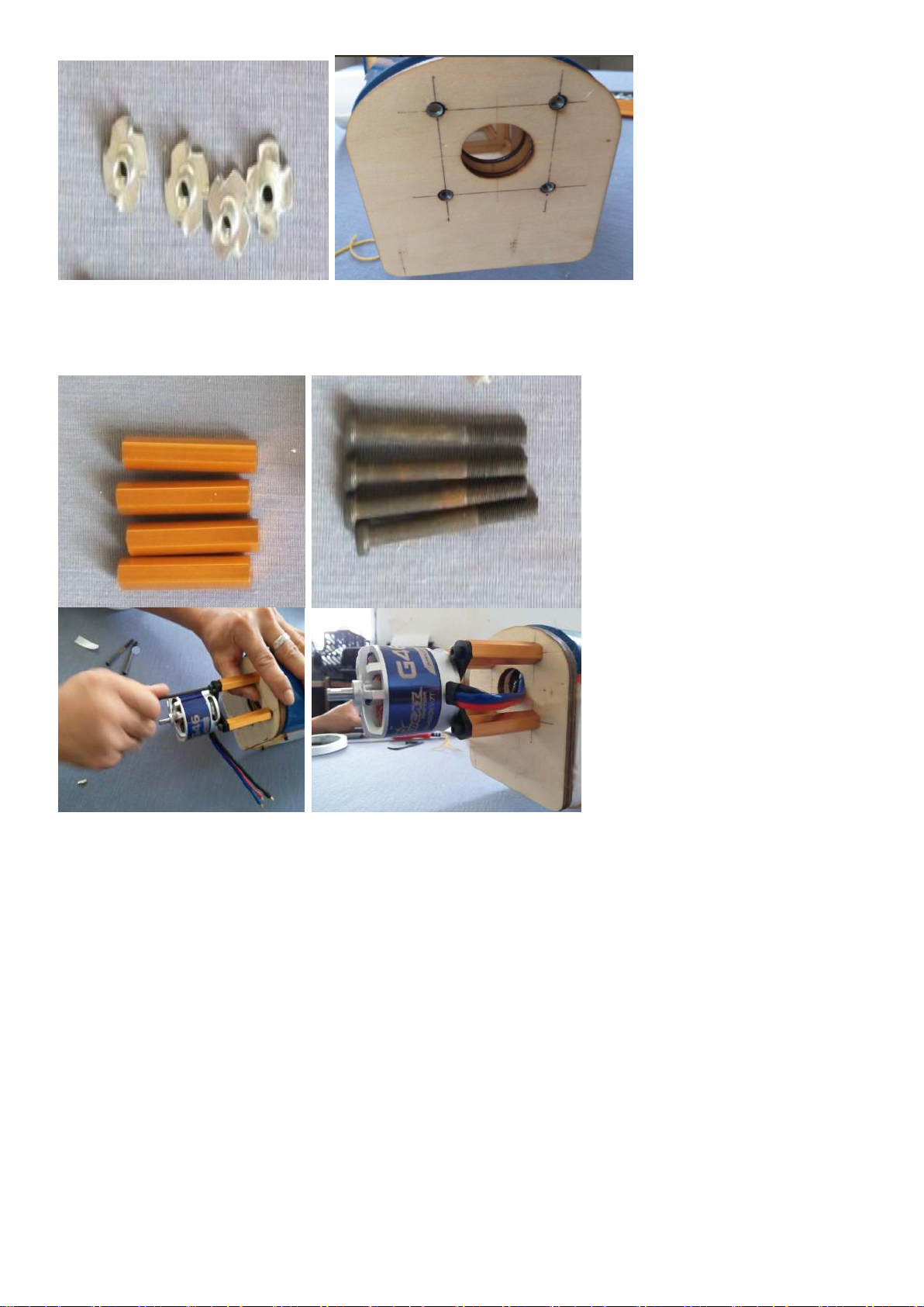
□step 5
Use 3mm hex wrench or ball driver to install the motor on the fire wall, as the picture shown.
22
Page 23
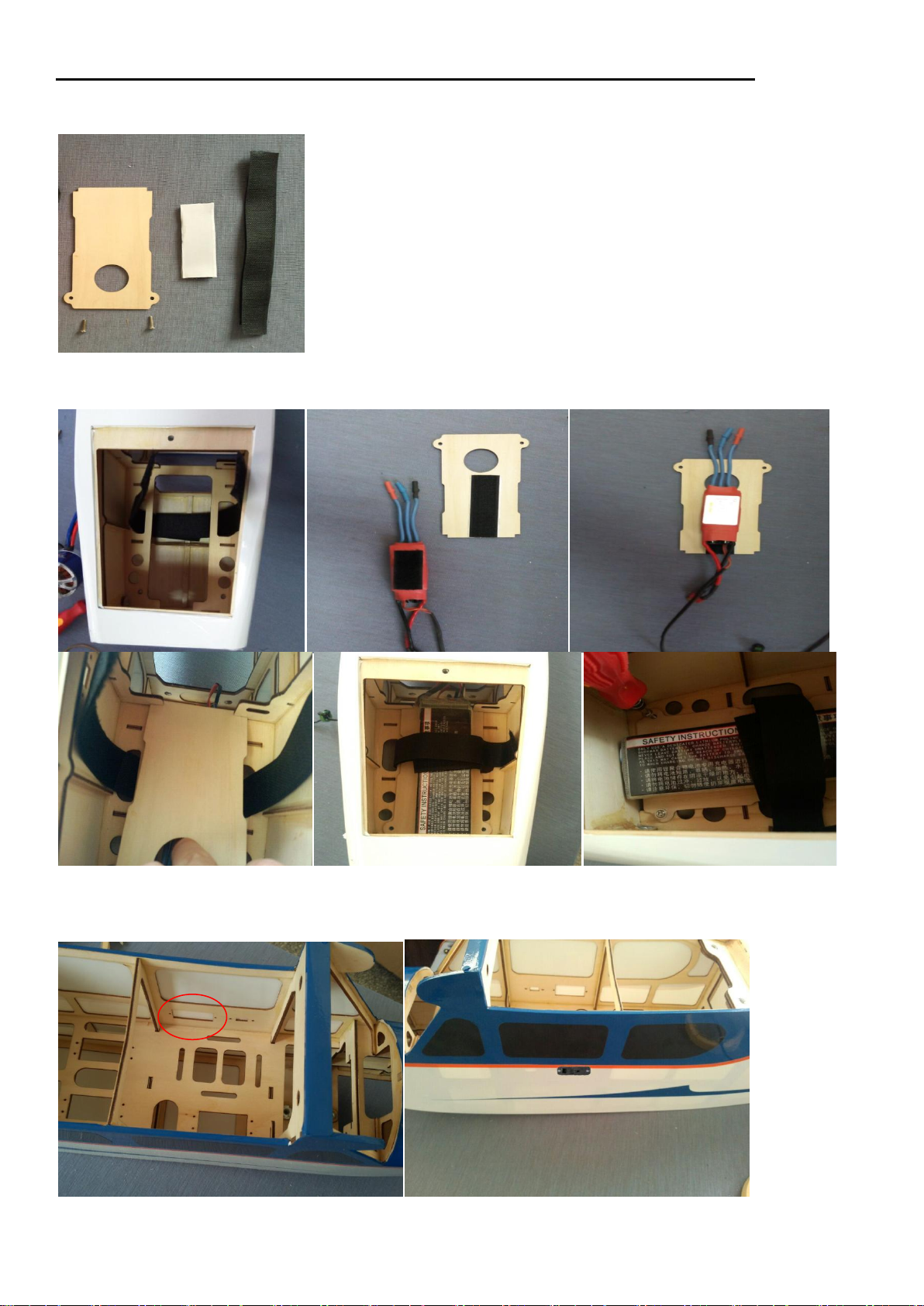
Section9 –electronic speed controller and his switch and battery installation
□step 1
Find the parts in the hardware pack, the ESC and battery need to buy.
□step4
Insert the battery tray in the fuselage with the speed control facing to the top of the fuselage,
□step5
Use a hobby knife to chip-off the cover of the switch position, as the picture shown.
□step6
23
Page 24
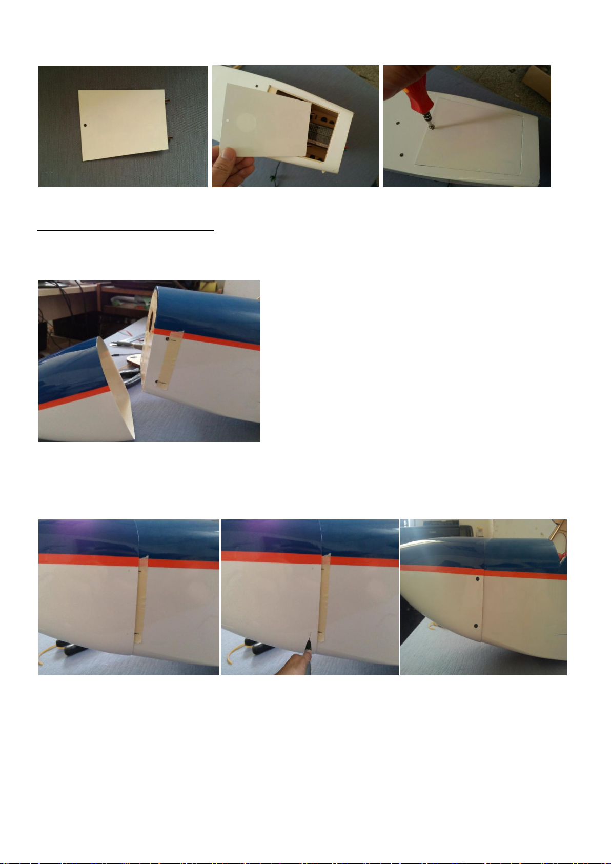
After install the electronic speed controller and switch and battery, install the cover plate, as the picture
shown.
Section 10 – cowl installation
□□step 1
Apply a piece of masking tape on the line were you have to make the holes for the cowl fixing
screws, than mark the position as per the picture.
□□step 2
Slide the cowling onto the fuselage and install the spinner back plate. Then apply another piece of
masking tape on the same line of the one applied before. Drill the location for the four self-tapping
screws using a 3mm drill bit.
□□step 3
Attach the cowl using the four M3*10mm self-tapping screws with shoulder washer, included in hardware
pack, with a Phillips screwdriver.
24
Page 25
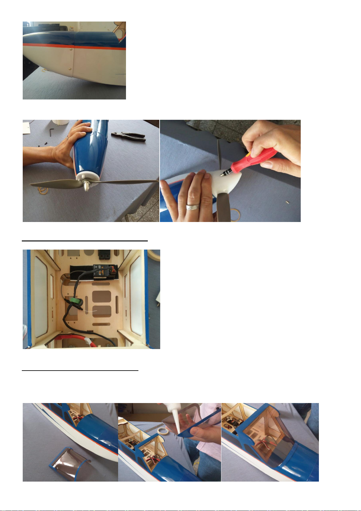
□step 4
Fix carefully the prop and the spinner as per picture.
Section 11 – final radio installation
Install the receiver, as the picture shown.
Section 12 – window installation
□step1
Apply some glass sealant on the window edge, and fix it on the fuselage wait the sealant to
dry, as picture shown.
25
Page 26
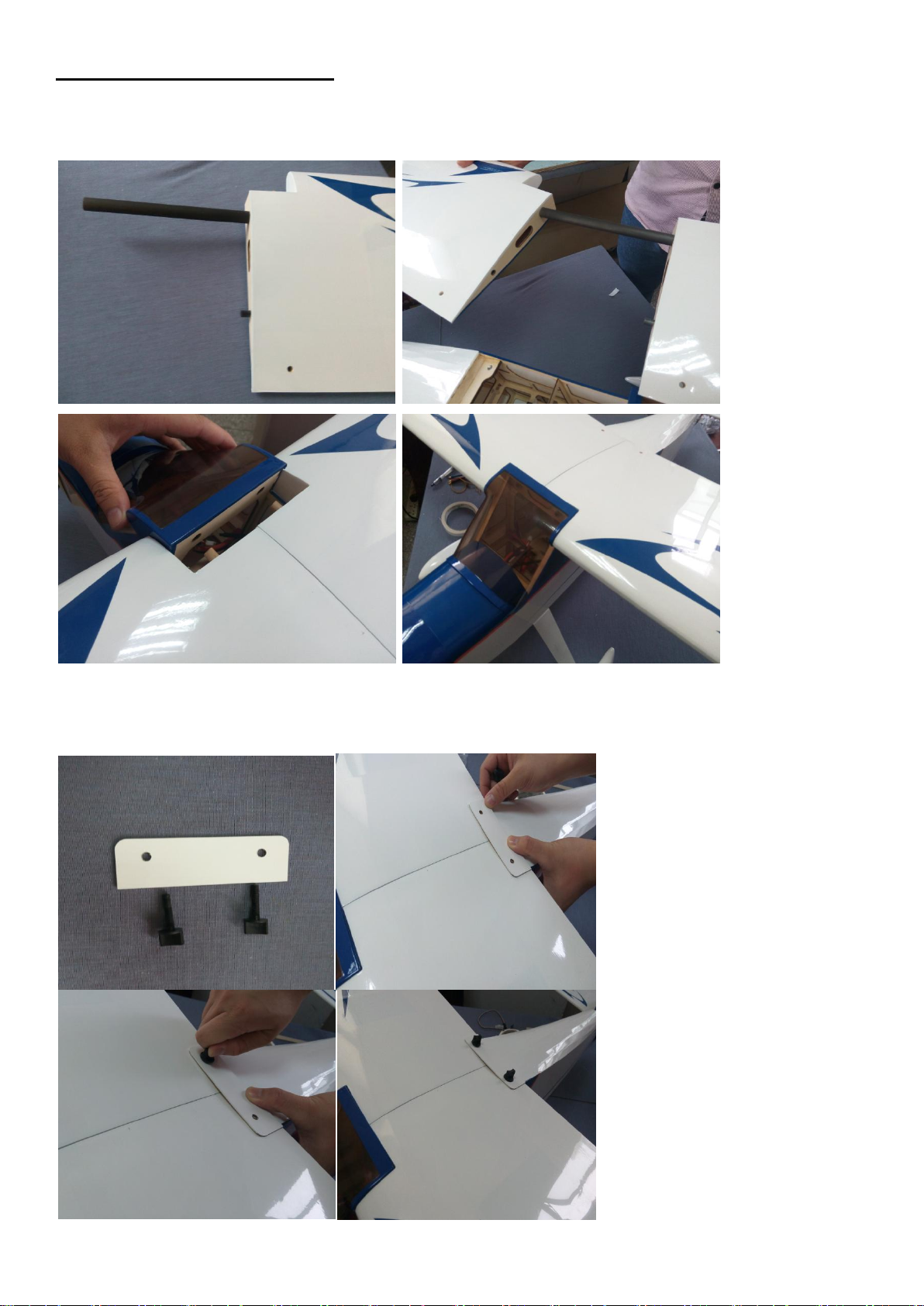
Section 13 – wings installation
□step1
Install the carbon fiber tube into the main wing, as the picture shown.
□step2
Find the past in the hardware pack to retaining the wing, as picture shown.
26
Page 27

Control Throws
□ Step 1
Turn on the transmitter and receiver of your model. Check the movement of the rudder using the transmitter. When
the stick is moved right, the rudder should also move right. Reverse the direction of the servo at the transmitter if
necessary.
□Step 2
Check the movement of the elevator with the radio system. Moving the elevator stick toward the bottom of the
transmitter will make the airplane elevator move up.
□Step 3
Check the movement of the ailerons with the radio system. Moving the aileron stick right will make the right aileron
move up and the left aileron move down.
□Step 4
Use a ruler to adjust the throw of the elevator, ailerons and rudder.
Aileron High Rate
Up 1-inch (25mm) 23 Degrees
Down 1-inch (25mm) 23 Degrees
Aileron Low Rate
Up 5/8-inch (16mm) 14 Degrees
Down 5/8-inch (16mm) 14 Degrees
Elevator High Rate
Up 13/8-inch (35mm) 21 Degrees
Down 13/8-inch (35mm) 21 Degrees
Elevator Low Rate
Up 7/8-inch (22mm) 14 Degrees
Down 7/8-inch (22mm) 14 Degrees
Rudder High Rate
Left 11/2-inch (38mm) 25 Degrees
Right 11/2-inch (38mm) 25 Degrees
Rudder Low Rate
Left 1-inch (25mm) 17 Degrees
Right 1-inch (25mm) 17 Degrees
Note
: Measurements are taken at the widest point on the control surface. These are general guidelines measured
from our own flight tests. You can experiment with higher or lower rates to match your preferred style of flying.
Note
: Travel Adjust, Sub Trim and Dual Rates are not listed and should be adjusted according to each individual
model and preference.
Rates and expos
Use the recommended expos to soften the feel of the model, especially on high rates. The goal is to
get the model to feel the same around neutral as it does on low rates.
Use low rate settings for all flying, included starts and landings, and high rate for snap, spins etc.
Center of Gravity(CG)
An important part of preparing the aircraft for flight is properly balancing the model.
Caution: Do not inadvertently skip this step!
The recommended Center of Gravity (CG) location for the your model is 23/4-inch (70mm) back, or 25% of
the chord, from the leading edge of the wing. Mark the location for the Center of Gravity on the bottom of
the wing next to the fuselage as shown. The CG range for your model is 21/2 to 3 inches (64mm to 76mm)
from the leading edge of the wing When balancing your model, support the plane upright at the marks made
on the bottom of the wing with your fingers or a commercially available balancing stand. This is the correct
27
Page 28
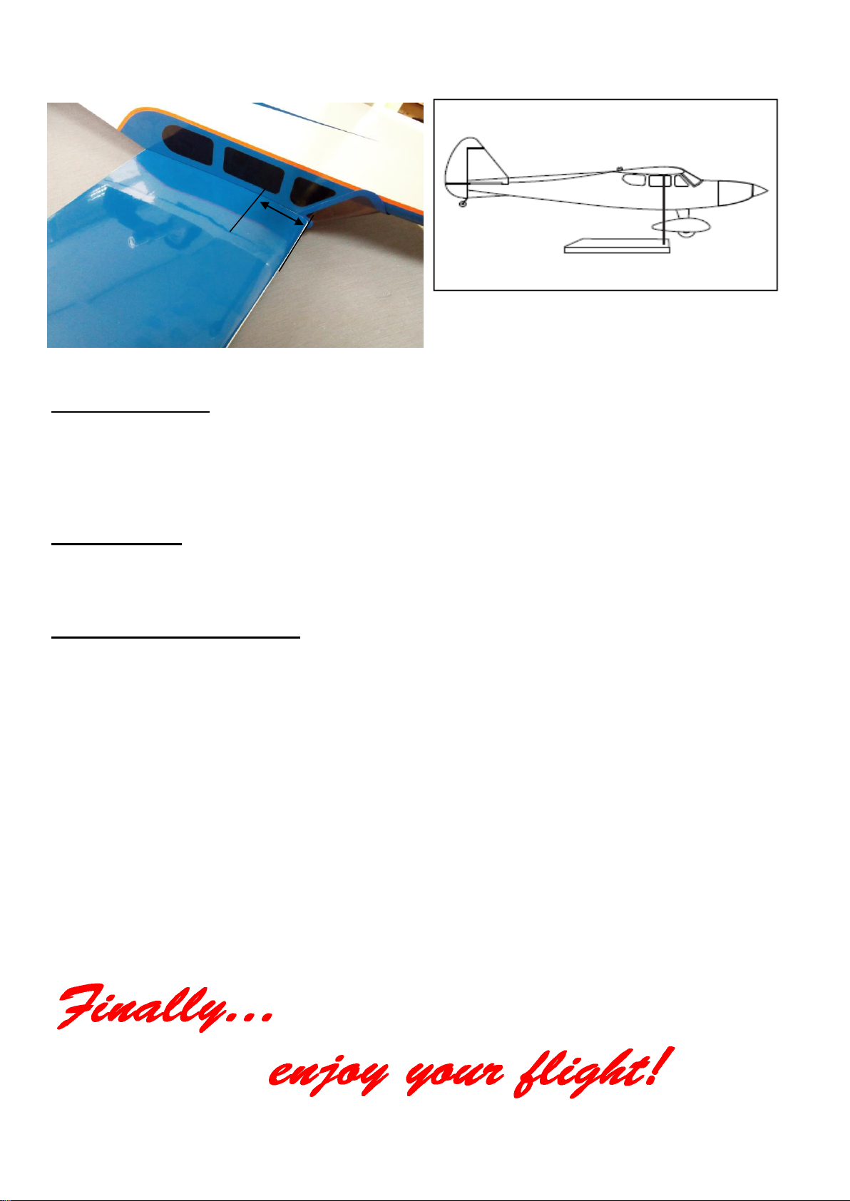
balance point for your model. You might find you may be required to add a small amount of weight to either
After the first flights, the CG position can be
adjusted for your personal preference.
23/4-inch
(70mm)
the front or back of the fuselage to achieve the correct balance.
Range test your radio
Before fly, be sure to range check your radio as manufacturer’s instruction manual of you radio-system
recommend.
Double-check all controls (aileron, elevator, rudder and throttle) move in the correct direction.
Be sure that your Flight Power batteries are fully charged, as per the instructions and that your radio is
fully charged as per its instructions.
Age requirements
Age Recommendation: 14 years or over. This is not a toy. This product is not intended for use by children
without direct adult supervision.
Safety, Precautions and Warnings
As the user of this product, you are solely responsible for operating it in a manner that does not endanger
yourself and others or result in damage to the product or the property of others.
Carefully follow the directions and warnings for this and any optional support equipment (chargers,
rechargeable battery packs, etc.) that you use.
This model is controlled by a radio signal that is subject to interference from many sources outside your
control. This interference can cause momentary loss of control so it is necessary to always keep a safe
distance in all directions around your model, as this margin will help to avoid collisions or injury.
• Always operate your model in an open area away from cars, traffic or people.
• Avoid operating your model in the street where injury or damage can occur.
• Never operate the model out into the street or populated areas for any reason.
• Never operate your model with low transmitter batteries.
• Carefully follow the directions and warnings for this and any optional support equipment (chargers,
rechargeable battery packs, etc.) that you use.
• Keep all chemicals, small parts and anything electrical out of the reach of children.
• Moisture causes damage to electronics. Avoid water exposure to all equipment not specifically designed
and protected for this purpose.
28
 Loading...