

Page 1
Instruction manual
Page 2
SPECIFICATIONS
• Fuselage: Length 950mm
• Wingspan: 1000mm
• Flying Weight: 450 - 500g (with battery)
• Additional Required Equipment (not included in the kit)
• Motor: 2212 1000KV or 2213 1000KV
• ESC: 20A
• Propeller: 1047 Slow Flyer Prop
• Servo: 4 x 9 grams
• Radio: 4 or more channels
• Battery: 11.1V 850-1300mAh li-po
SAFETY PRECAUTIONS
1. We recommend that you get the assistance of an experienced pilot during the
assembling process.
2. The kit contains small parts. So keep out of children's reach when assembling.
3. The flying weight of the plane is about 400 grams of weight. In order to ensure the plane has
the best flight performance, please use a motor and a battery pack within the weight recommendation.
1
Page 3
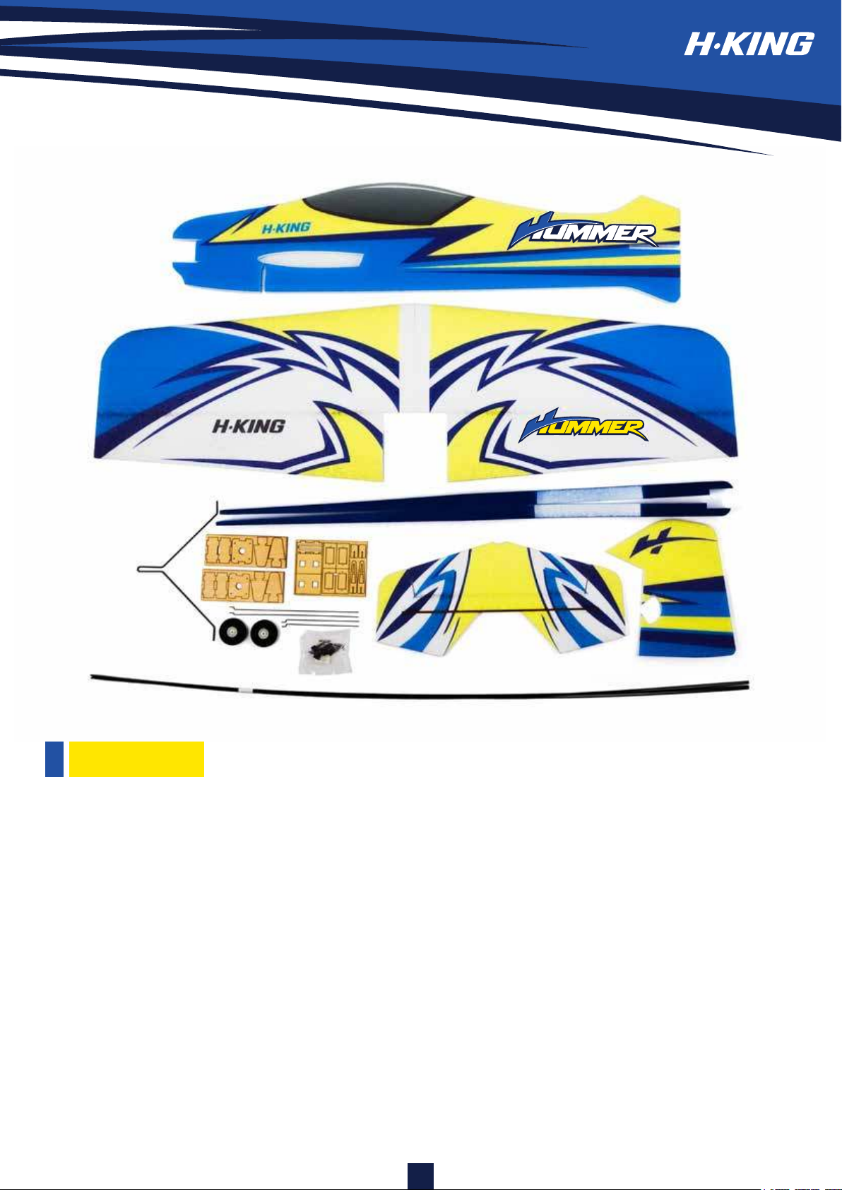
PARTS LIST:
• Main wing L and R : 1 pc/each
• Fuselage : 1 pc
• Stiffened of Fuselage : 2 pcs
• Stabilizer : 1 pc
• Rudder : 1 pc
• Plywood Motor Mount : 1 set
• Z-shaped steel wire : 4 pcs
• Airplane wheel and plastic wheel chock : 2 pcs
2
• Landing gear steel wire : 1 pc
• Wood support plate of landing gear 1 set
• Servo horn : 4 pcs
• Heat shrink tube : 1 pc
• 990 mm Carbon rod: 2 pcs
• 780mm Carbon rod: 3 pcs
• 330mm elevator 330 mm wood strip: 2 pcs
• Hinge : 4 pcs
Page 4
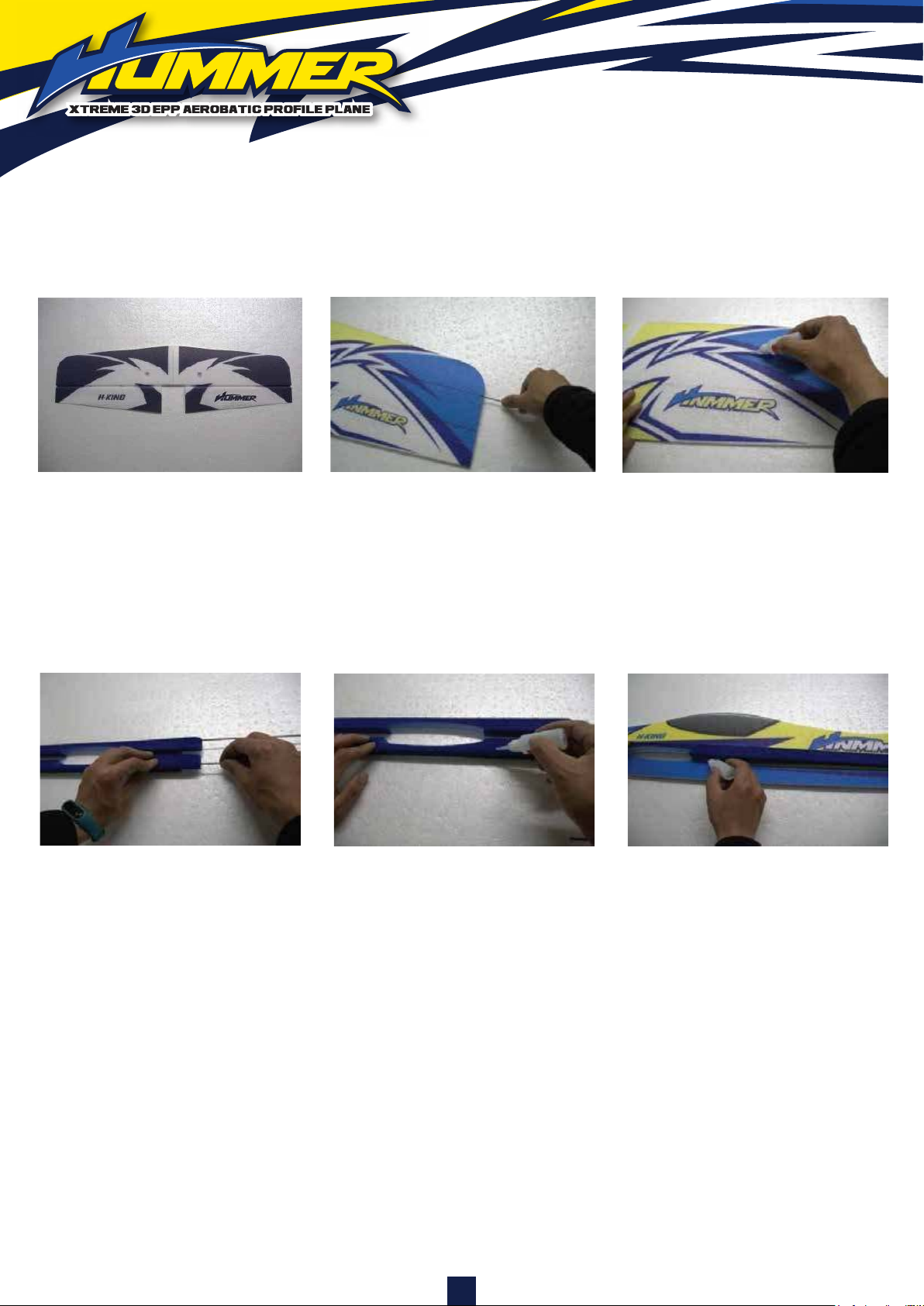
1 32
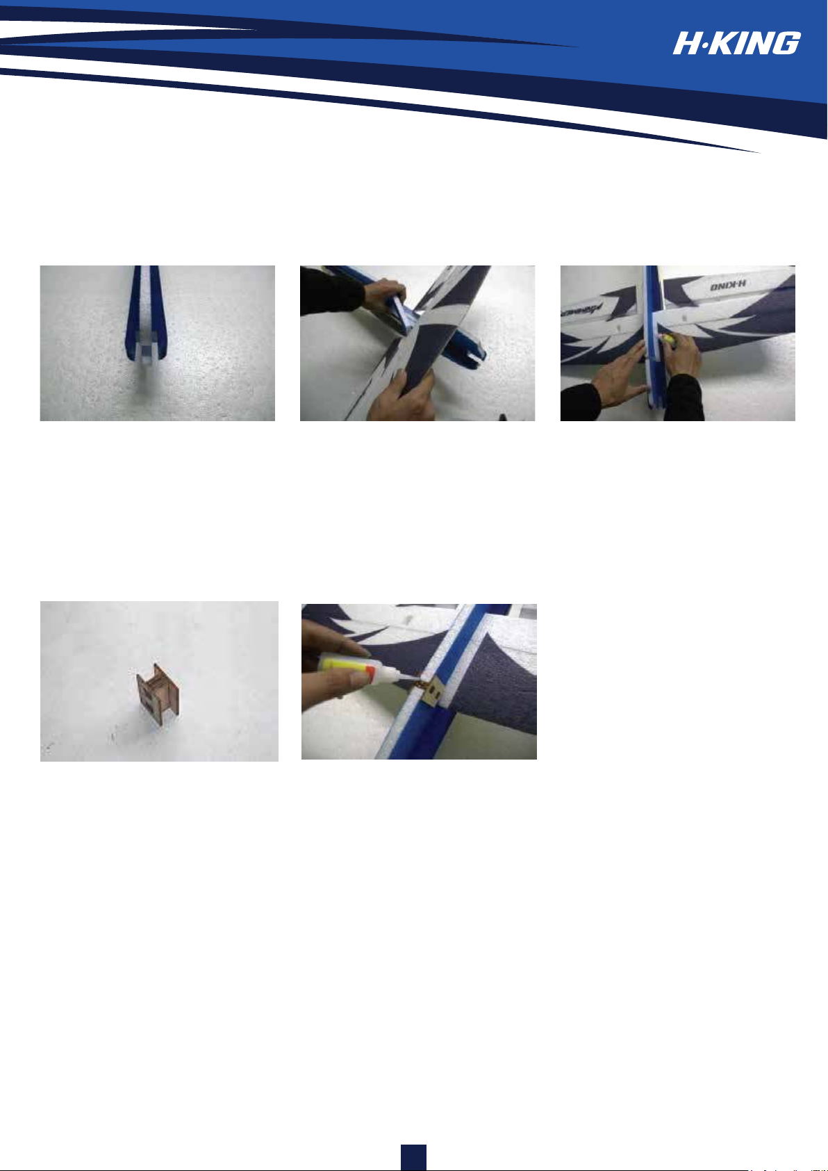
1. Join two wing halves together with foam-safe glue.
2. Insert two pieces of 990mm x 2mm carbon rods to the wing's top and bottom surface respectively.
3. Glue and secure the carbon rods to the wing's top and bottom with foam-safe glue.
4 65
4. Insert 2 pieces of carbon rods with the length of 780mm into the slot of the stiffener as shown.
Note: Pay attention to the left/right direction.
5. Lay the fuselage on a flat surface and glue the stiffener on to the fuselage as shown. Please do
both sides. Note: Ensure both stiffeners are well aligned properly to the wing slot and the stabilizer
slot as well. Wait till the glue is dry.
6. You may glue the carbon rod with foam-safe glue at this time.
3
Page 5
7 98
7. Ensure the fuselage is arrow-straight. Wait till the glue is dry.
8. Insert the wing into the fuselage wing slot. (See picture)
9. Before apply glue onto the wing and fuselage joints, ensure the wing is centred and perpendicular
to the fuselage. If it looks good, apply foam-safe glue to the joints and check the squareness
frequently while waiting for the glue to dry.
10 11
10. Glue the supplied landing gear wood mount assembly as shown.
11. Glue the landing gear mount to the fuselage with foam-safe glue. Note: The landing gear slot
should be pointed upward.
4
Page 6
12 1312
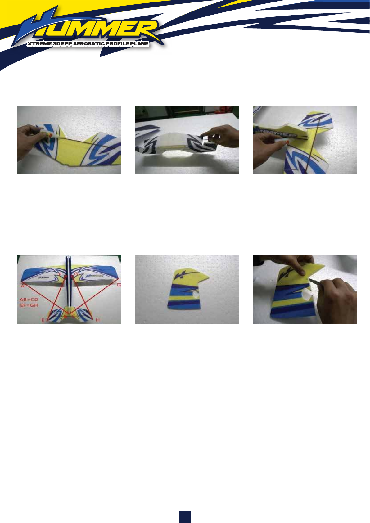
12. Lay the elevator on a flat surface. Insert two supplied 330mm x 4mm wood strips into the slots on
the elevator and stabilizer respectively. Once statisfied with the fit. Apply glue to the wood strips
and let it dry.
13. Install the stabilizer onto the fuselage as shown
14 15 16
14. Please ensure the stabilizer is squared and parallel to the main wing first.
Once satisfied with the fit, apply glue to the joints between the wing and the fuselage. Set it
aside and wait till the glue to dry.
15. Install a supplied plastic horn onto the rudder. The rudder horn should be positioned 92mm
from the rudder base. The holes on the control horn should be aligned to the hinge line to
ensure the rudder deflection is symmetrical
16 Use a Xacto knife to make 4 evenly spaced slots on the rudder as shown. Insert 4 paper
hinges halfway into the slots and glue it. Wait till the glue to dry.
5
Page 7
17 18 19
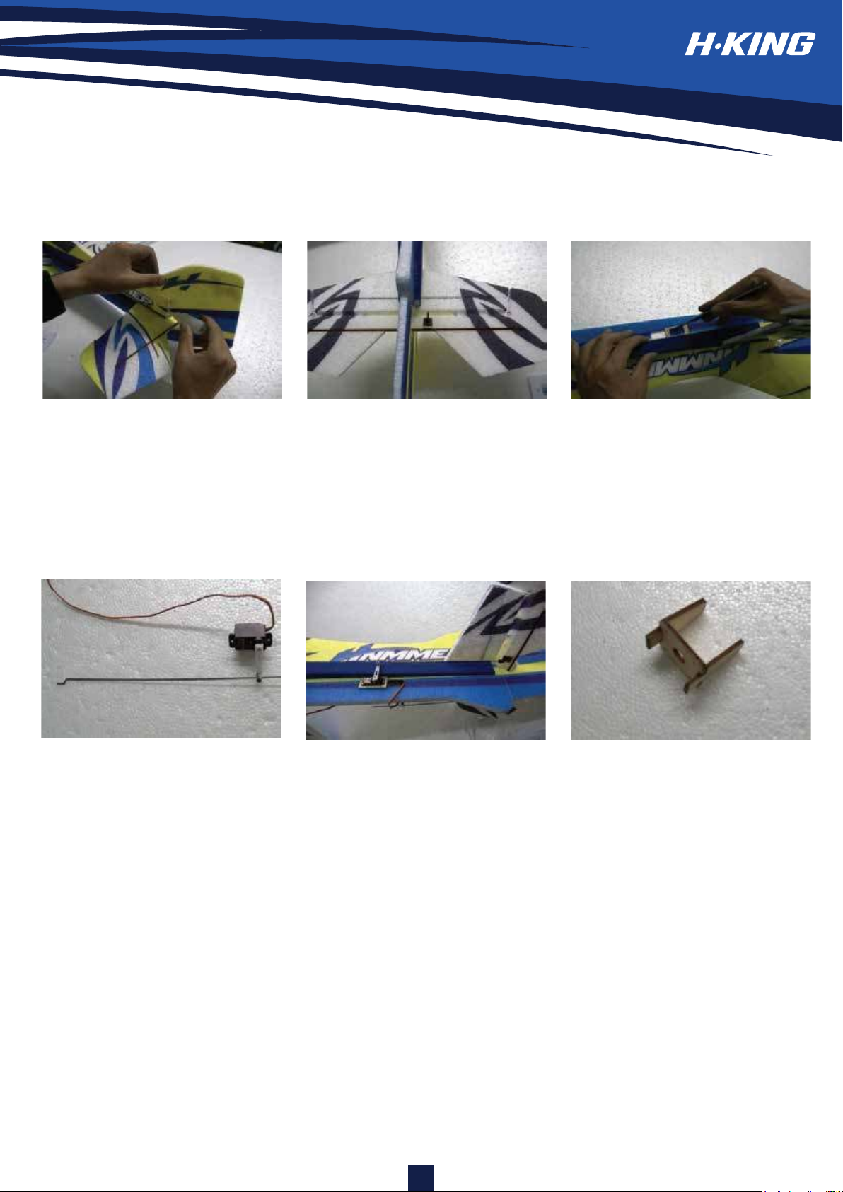
17. Use a Xacto knife to make another 4 slots which correspond to the ones on the rudder. Then
insert those paper hinges to the rudder post and apply glue to secure it.
18. Install the supplied plastic horn on the elevator as shown.
19. Make a cutout on the fuselage for the elevator servo. The cutout location should be 13cm
away from the fuselage rudder post.
20 20 21
20. (This step applies to all the control surfaces set-up on this plane) When install the pushrod linkage
to the elevator, ensure the servo horn and control surface is level. Install the pushrod adjuster to the
servo horn and also install the pushrod at the same time. Once satisfied with the fit, tightened the
grub screw on the adjustor and trim the excess of the pushrod.
21. Assemble the plywood motor mount and apply glue to all the joints.
6
Page 8
22 23 24
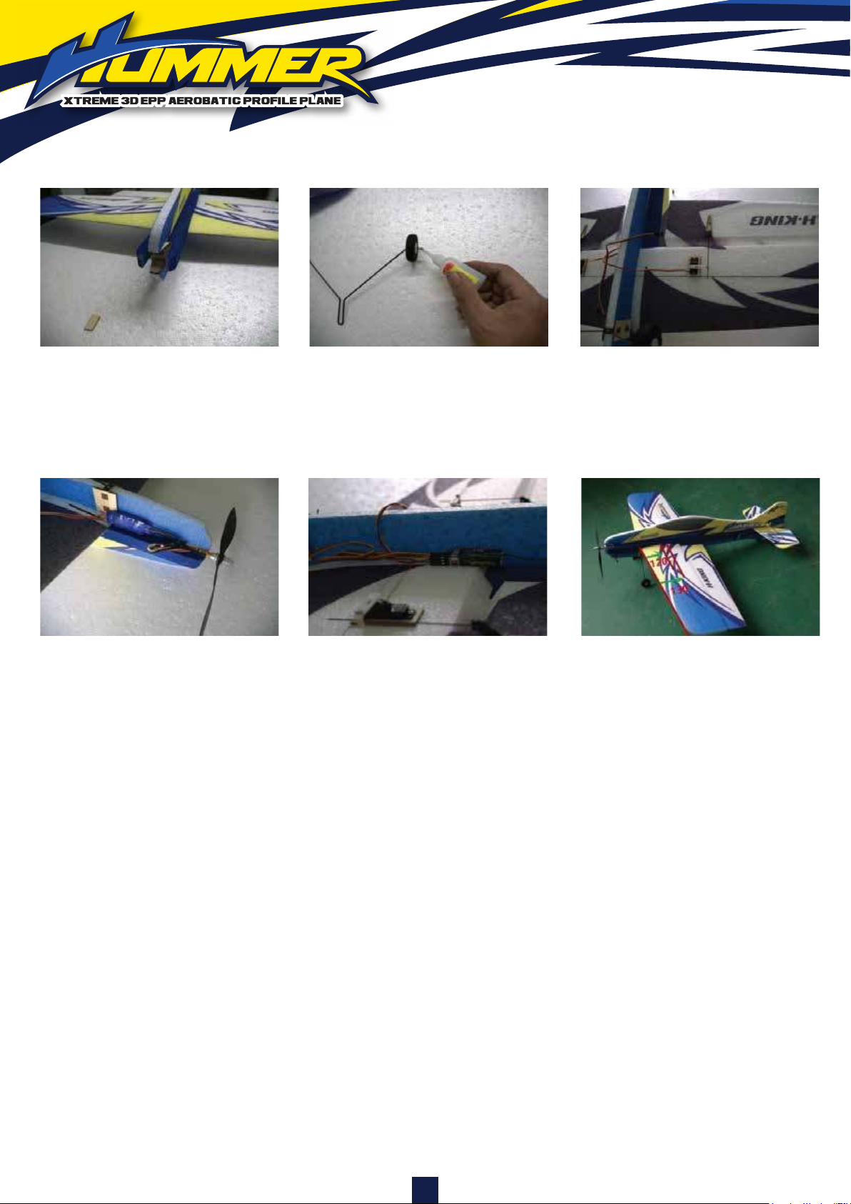
22. Install and glue the motor mount to the fuselage as shown.
23. Insert both wheels on the steel wire and use hot shrink tube to hold the wheels in place.
24. Install the landing gear to the mounting plate as shown.
25 26 27
25. Install your desired brushless motor to the motor mount with tapping screws.
26. Use a set of velcro tape to attach your desired radio receiver to the fuselage. Note: Be prepared to
move the receiver back and forth to achieve the right C of G. Use a set of velcro tape to attach your
desired battery pack on the front part of the fuselage.
Note: Be prepared to move the receiver back and forth to achieve the right C of G.
27. The centre of gravity should be 120-130mm from the front edge of aircraft wing.
We suggest that you add 1- 2 degrees of right-thrust, which can be achieved by adding
one washer or two behind the top and right side of the motor (between the motor and the
motor mount). When set properly, the trim for the elevator and the rudder should be
neutral. Fine-tune the down-thrust and right-thrust until this trim is achieved. When doing
flight test, we suggest you should keep the flight balance according to the centre of gravity
we recommend. When doing 3D flight test, you can move slightly the centre of gravity
backward.
General flight: Aileron: 20 degrees, Elevator: 20 degrees, Rudder: 20 degrees.
3D flight: Aileron : 45-55 degrees, Elevator: 45-60 degrees, Rudder: 45-60 degrees.
Seek Assistance: If you are a beginner in the R/C field, we suggest you turn to an
experienced pilot for help with the first few flights.
7
Page 9

 Loading...