

Page 1
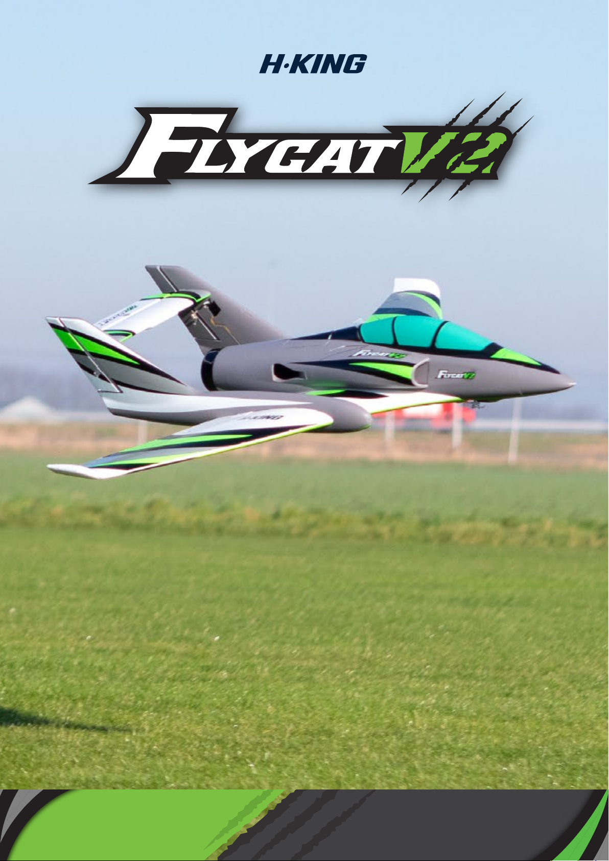
INSTRUCTION MANUAL
1042mm EDF JET with pre-installed 70mm Fan,
Motor, ESC, Servos, and Retracts.
Page 2

MANUAL CONTENTS
Introduction and Specifications -----------------------
Warning & Safety Notes --------------------------
Contents -------------------------------------------
Assembly ----------------------------------------
Center of Gravity ------------------------------------
Control Throws -------------------------------------
ESC Set Up -----------------------------------------
Flying Tips -----------------------------------------
Recommended Accessories -----------------------
---3/4
6/14
19/21
2
4
15
16
17
18
01
Page 3

INTRODUCTION
After the success of
model with no retracts, it was decided to follow this with a new V2 version. The
Flycat V2 has been updated with a new 12-blade 70mm fan unit driven by a
powerful 2860-2100KV inrunner motor, dual rudders for added control and agility,
a set of pre-installed electronic retracts, and a brand new high-viz color scheme.
It retains from the V1 its stunning, streamlined looks and impeccable flying
characteristics.
.
The Flycat V2 is supplied as a "Plug-N-Fly" model and comes complete with fan
unit, brushless motor, an Aerostar 80amp ESC with reverse, six 9g high
speed servos, and electronic retracts. All these items are pre-installed at the
factory as are the new colorful decals, so the time from starting the build to
having it ready to fly is minimal. All you will require is a 5ch or greater (if you want
to use the reverse function) transmitter, receiver, and a 6S 30~60C
3000~4000mah LiPo battery with a suitable charger.
the original Flycat, a basic aileron, elevator, and throttle-only
Specs:
Wingspan: 1042mm
Fuselage Length: 1115mm
EDF: 70mm 12 blade unit
Motor: 2860/2100Kv brushless
ESC: 80amp Aerostar RVS G2 w/reverse
Servos: 6 x 9g high speed (metal-geared for the
nosewheel)
Retracts: 3 x electronic w/steerable nosewheel
AUW: 2000~2100g
Battery: 6S 30~60C 3000~4000mAh LiPo (not supplied)
Radio: 5 channels or more (not supplied)
02
Page 4
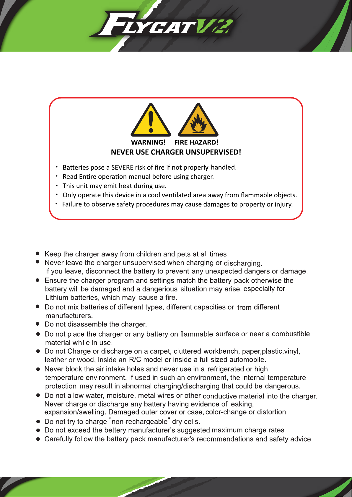
Warning on the use of LiPo batteries and their chargers.
Warnings and Safety notes
030405
Page 5
Page 6
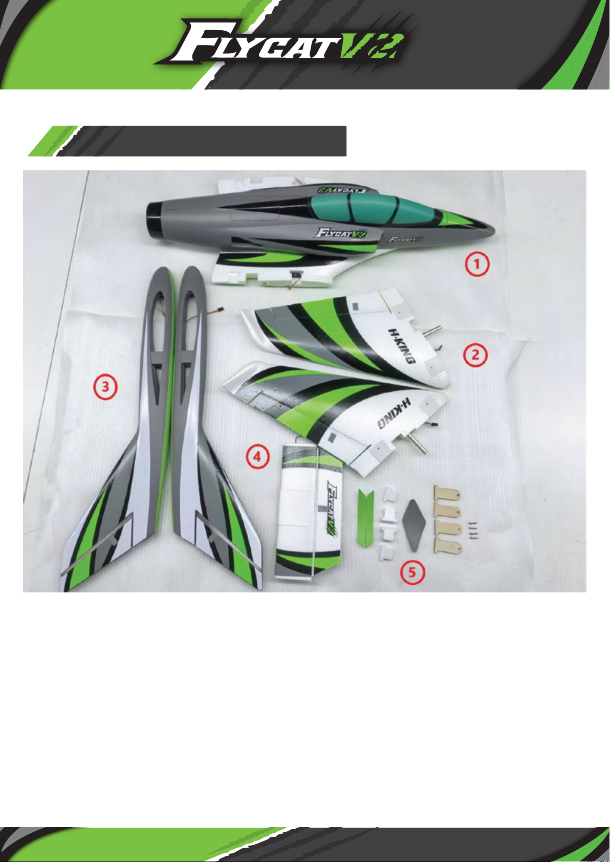
FLYCAT V2 CONTENTS:
1. Fuselage
2. Wings
3. Tailbooms
4. Horizontal stabilizer
5. Accessories
Page 7
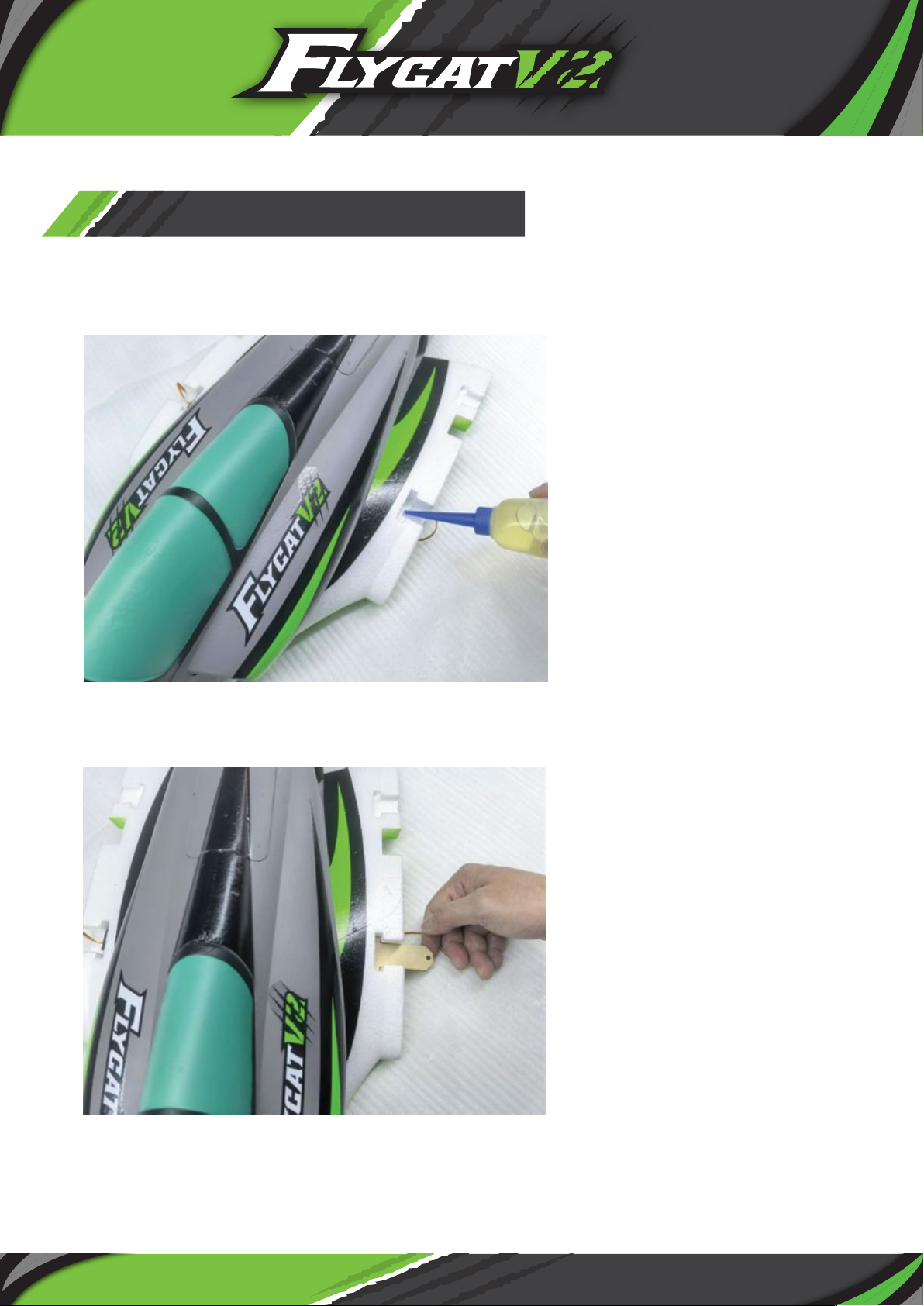
GENERAL ASSEMBLY
Please note: Before you glue together any parts that have paint on the
joints, rough them up first with sandpaper to achieve a better bond.
1. Using a slow cure CA or a similar apply the glue to the area of the fuselage
where one of the plywood wing retaining tongues is located.
2. Glue into place the plywood tongue as shown.
06
Page 8
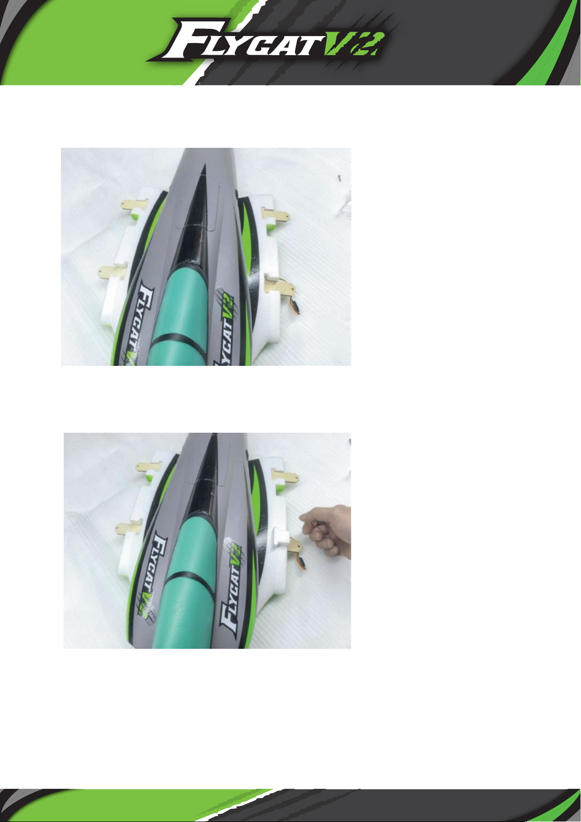
3. Repeat this process with the other 3 plywood tongues.
4. Glue into place the 4 foam in-fills on top of the plywood tongues.
07
Page 9
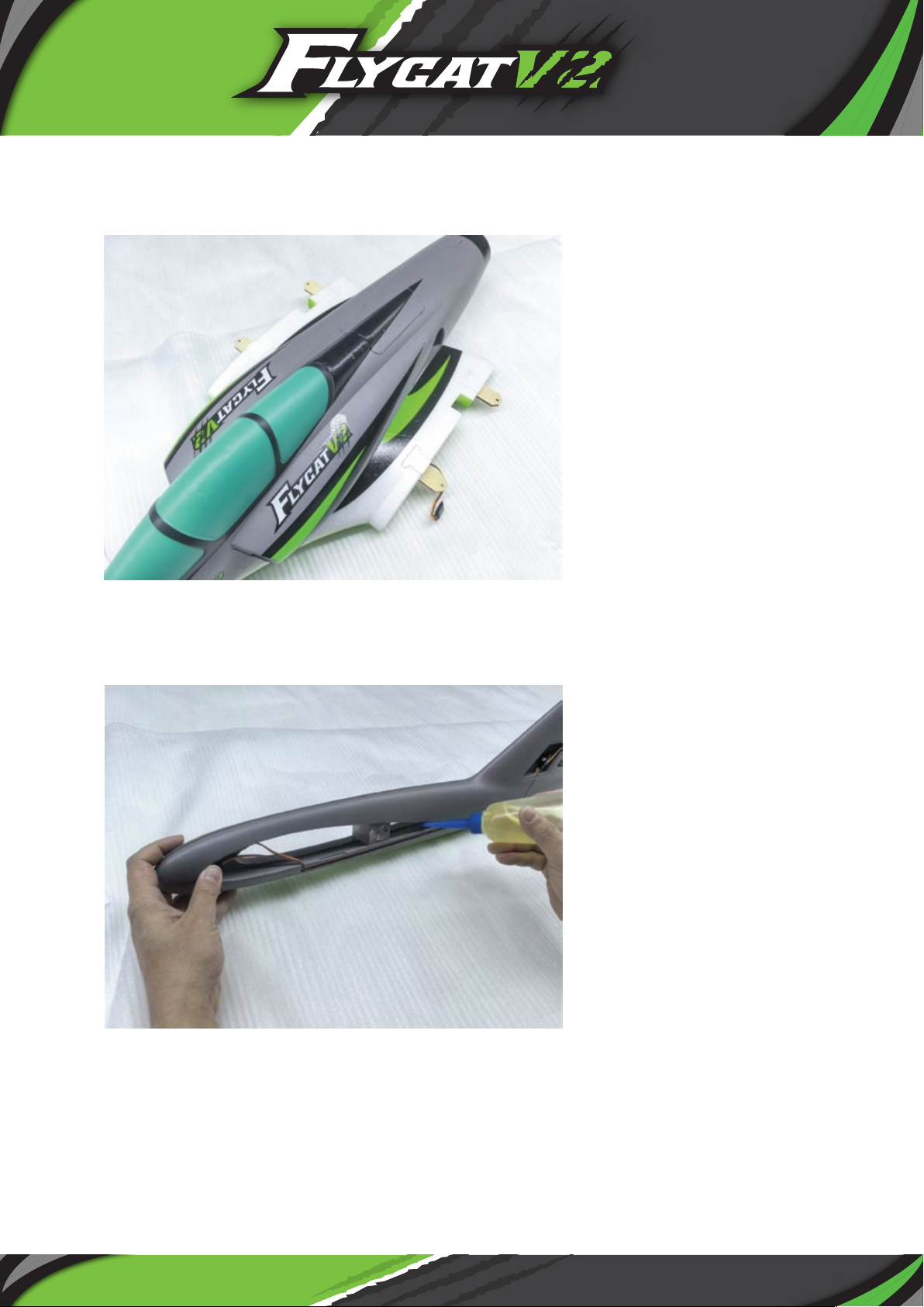
5.
This picture shows all 4 foam in-fills in place.
6. Apply slow setting CA or a similar glue into the recess on the
fuselage side of the tail boom that does not have the cut-out in the
vertical stabilizer.
08
Page 10
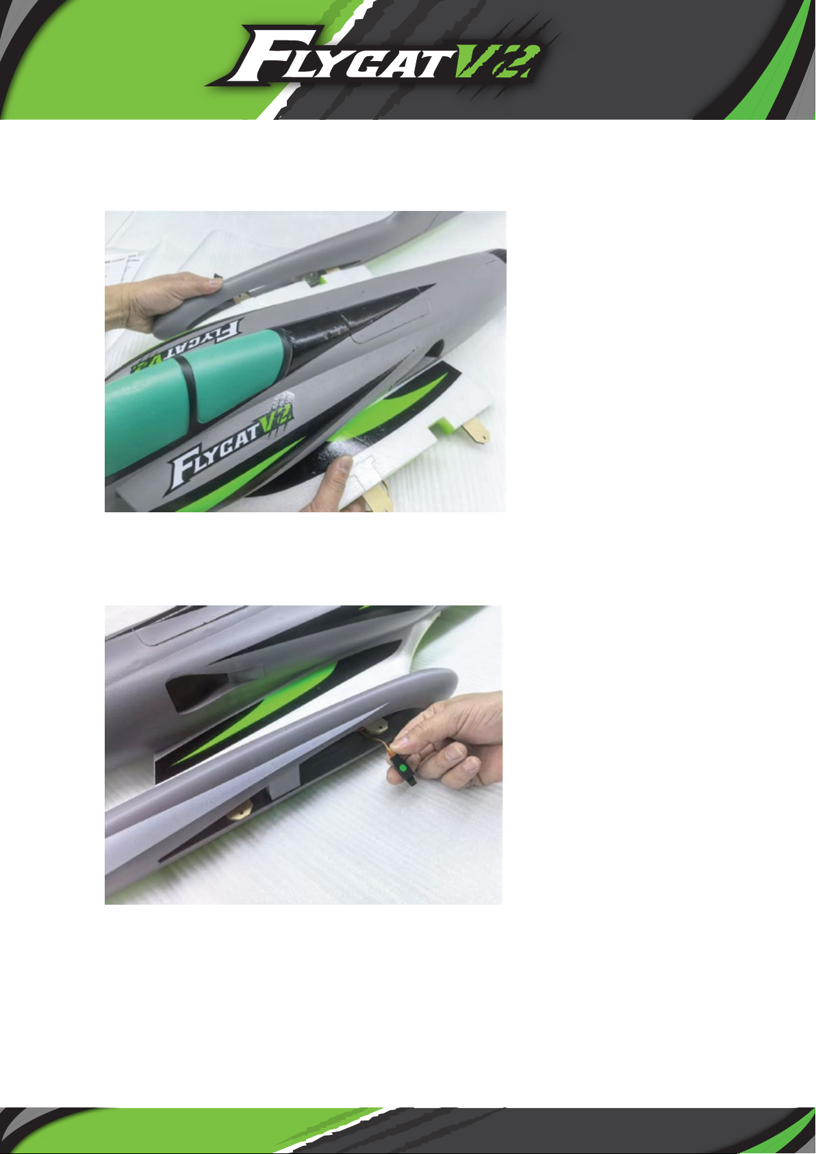
7. Slide the tail boom over the wing root of the fuselage as shown and
glue into place.
8. Please ensure the aileron servo connector is pulled through
the wing root.
09
Page 11
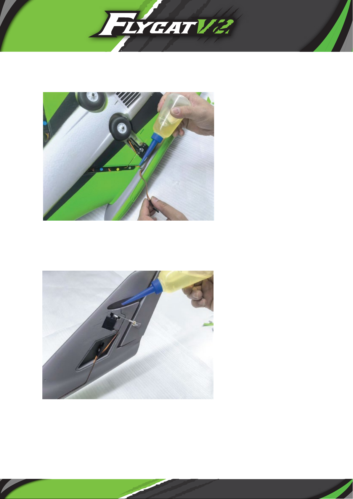
9. The elevator & rudder servo extension leads are already installed
in the tailboom. Connect these to the leads in the fuselage slot
and press into place, secure with either a drop of glue, or some
colored tape.
10. Apply some slow cure CA into the slot for the horizontal
stabilizer to be glued into.
10
Page 12
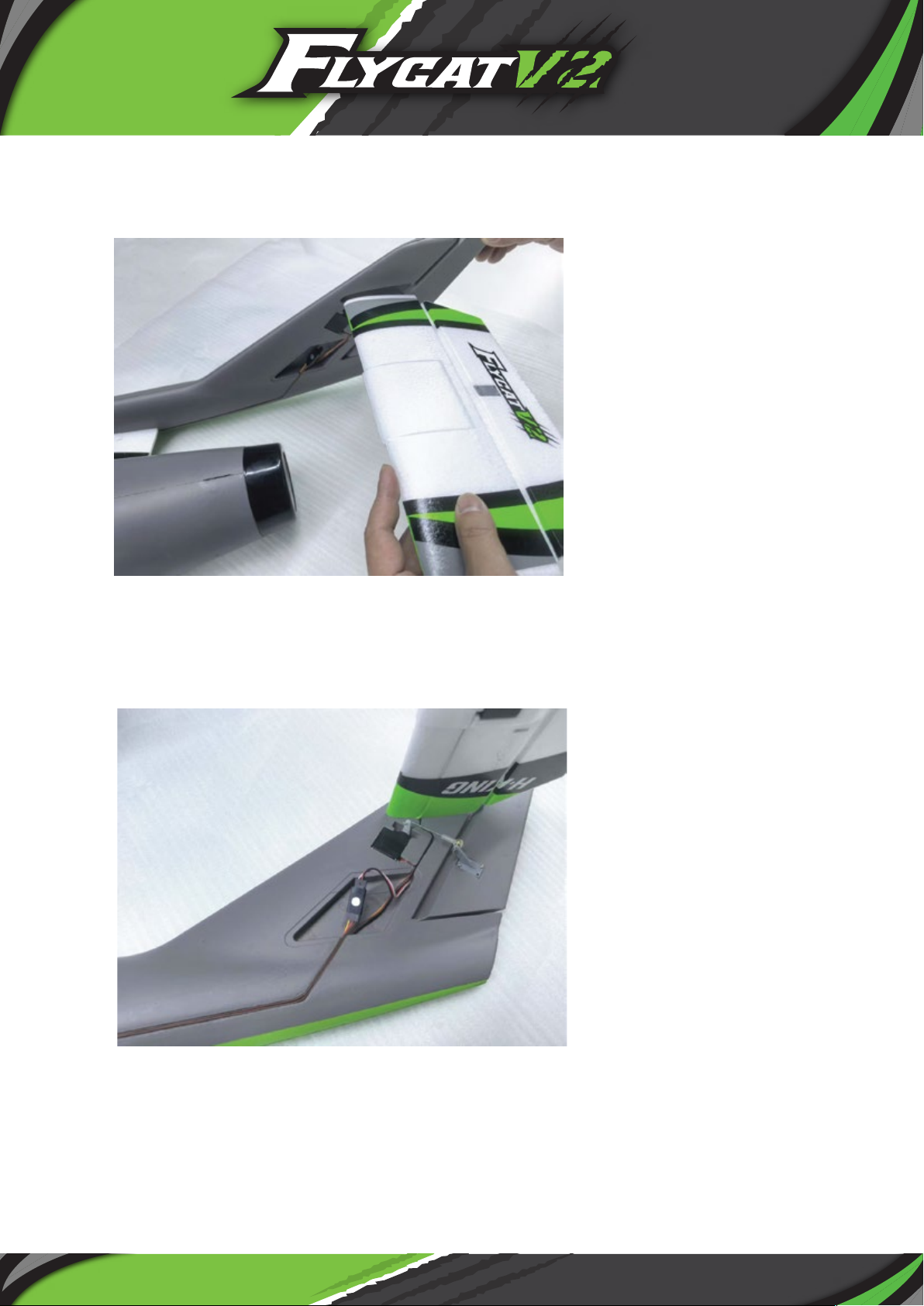
11. Fit the horizontal stabilizer into the slot in the vertical stabilizer
and allow the glue to set. Please ensure the assembly stays square
as the glue sets.
12. Feed the elevator servo lead into the slot in the vertical stabilizer
and connect in to the socket in the cut-out as shown.
11
Page 13
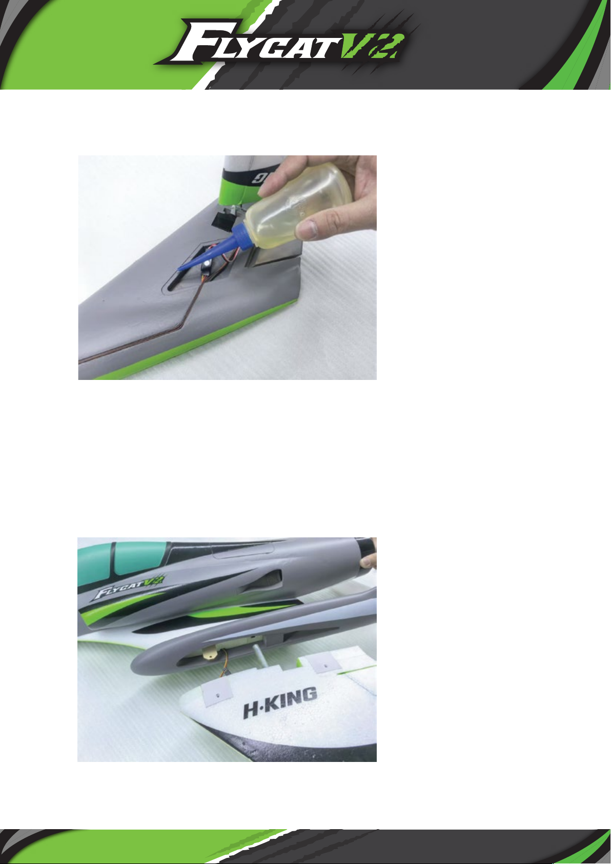
13.
Apply CA glue to the recess in the cut-out and glue
into
place the triangular cover supplied.
14. At this point, follow the steps of gluing in place the first tailboom
and glue into place the second one, including gluing in the
horizontal stabilizer. Do not forget to feed the aileron servo lead
out of the wing root in the fuselage and to connect the rudder
servo extension lead into the socket in the fuselage wing root.
15. Connect the aileron servo lead together for one of the wings.
12
Page 14
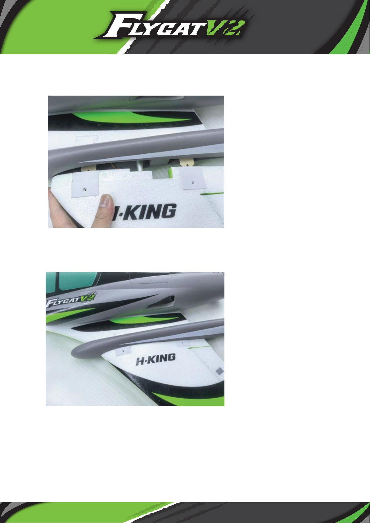
16. Slide the wing spar into the pre-installed tube in the fuselage
wing root.
17. Then slide the entire wing into the wing root until it is fully
seated and the holes line up with those in the plywood tongues.
13
Page 15
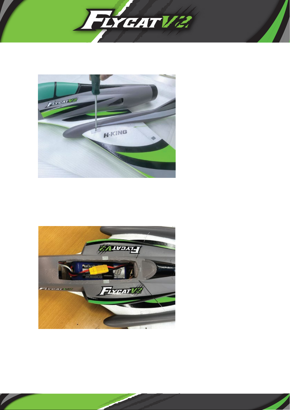
18. Screw the supplied PK screws through the plastic wing fixings
and into the plywood tongues.
19. Repeat this entire process to fit the other wing.
20. Install your chosen receiver in the recess at the rear of the
battery compartment, and then install your 6S battery as shown.
14
Page 16
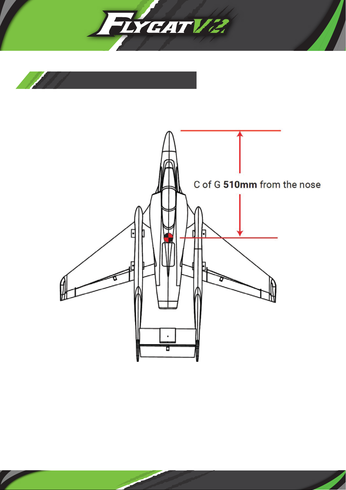
C of G Position:
C of G should be 510mm ± 5mm from the nose of the Flycat V2.
Adjust the position of the battery to achieve the correct balance
15
Page 17
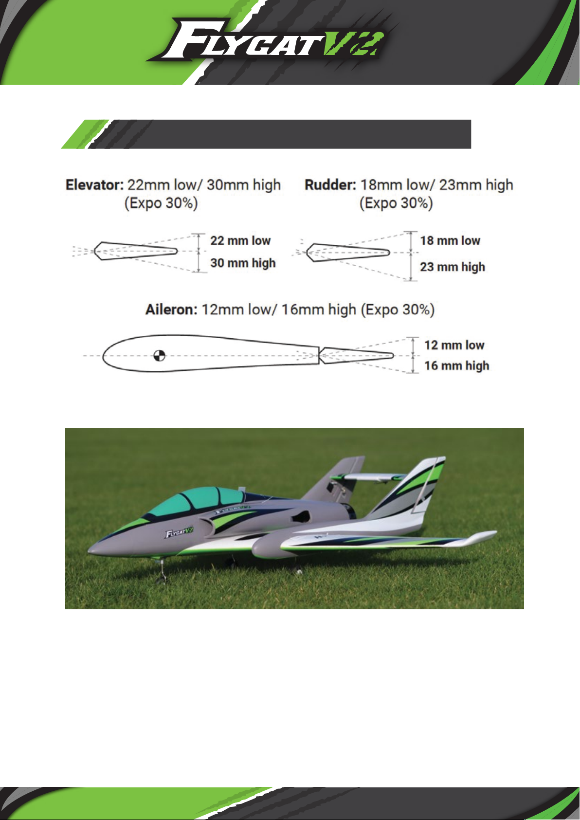
CONTROL THROWS LOW-HIGH
Your Flycat V2 should now be finished and ready to fly.
16
Page 18

SETTING THE ESC
The Flycat V2 is fitted with the Aerostar 80A RVS G2 instant reversing electronic
speed controller. Setting the reverse on the ESC would be ideal if you are flying from
a hard surface to shorten the landing run.
1.
It is important that you manually calibrate the throttle range when using the ESC for
the first time, this should always be done with the propeller removed. Move the
throttle stick to the full throttle position and switch on the transmitter (ensure the
end points are set to 100%, and the throttle trim is in the middle). Connect your
battery pack to the ESC and wait for 2 seconds, your motor will now give 2 quick
beeps (Beep-Beep), as soon as you hear these beeps, lower your throttle to the fully
closed position, the ESC is now calibrated and ready for use.
2. When you switch on your transmitter each time to fly, you need to make sure the
throttle stick is in the low/off position, then when you connect the flight battery the
motor will emit a series of beeps. When using a 6S pack, 6 beeps with the same tune
means the ESC has detected the 6 cells of the battery. The motor is now armed and
will start when the throttle is opened.
3. The motor and ESC come pre-connected, and the motor rotation should be correctly
set. If for any reason the motor is rotating in the wrong direction, simply swap over
any two of the three motor to ESC wires to change the direction of rotation.
4. By default your RVS 80amp should have RVS set to 'on'. If however, you have installed
the yellow RVS single lead from the ESC to a spare channel on your receiver that is
controlled by a 2-way switch on your radio, and you find that the RVS is not
functioning, it is recommended to double check the settings of the ESC.To do this,
move your throttle stick to the full throttle position and switch on the transmitter,
then connect your battery pack to the ESC. Wait for 2 seconds, the motor will then
emit a fast 2 beep tone (Beep-Beep). Wait for another 3 seconds and the motor will
emit a special fast multi-beep tone (Da-Da-Da-Dum) which means it has now entered
programming mode. After entering program mode wait for 2 short beeps, then close
the throttle immediately. Once this is done you will hear a sequence of tones in a loop
that corresponds to the values set, when you hear the 2 short beeps again move the
throttle stick back to the open position once more. The motor will now emit a special
"123" tone which indicates the value (RVS) is set to on.
5. The full instruction manual is available on the product page for the Aerostar G2 RVS
ESC's on our site, this shows you in detail how to programme all the ESC RVS
settings via your transmitter using the beep sequences.
17
Page 19

FLYING TIPS
Before you fly please check your controls and make sure you double
check the following.
Left aileron, the left aileron should go up, right aileron, the right aileron
should go up, back stick and the elevator should go up, forward stick
the elevator should go down, left rudder, rudders go left, right rudder,
ruuders go right. Double check that the model balances on the C of G
correctly, it should balance at the 510mm ± 5mm mark in a slight nose
down attitude (do this with the model inverted and the wheels retracted).
Now you’re ready to for your first flight, please make sure you do a
range check of your radio equipment first.
The H-King Flycat V2 unlike the original which was a hand launched RC
airplane now has wheels for taking off from the ground. So line the
model up into wind on your take-off area, check once again that the
controls are working correctly. Then smoothly open the throttle whilst
holding a small amount of up elevator and keep the model straight using
the steerable nosewheel/rudders. Once it has reached flying speed it
should lift-off smoothly by itself, if not, increase the up elevator slightly
until it leaves the ground. Being a ducted fan you do not get the prop
wash as you do with a propeller driven plane so you do require airspeed
before you initiate a climb, so keep the climb shallow to start with until
the airspeed builds.
Once airborne and safely in the climb retract the landing gear and carry
on to a safe altitude to adjust your trim to get the Flycat V2 flying
straight and level on about ¾ throttle. If your plane is not flying
correctly land and adjust your radio or the linkages where necessary.
Once you have your Flycat V2 flying well it will perform as if it is on
rails, it's fast, smooth and manoeuvrable. You will be able to fly all the
usual jet like aerobatics with ease and it looks really great in the sky.
When it comes to landing line up your plane with the landing area and
lower the landing gear. Using your elevator to control pitch and speed,
throttle to control descent, ailerons to keep the wings level, and the
rudders to steer, simply glide the Flycat V2 home to a smooth, nicely
held off landing. As it's name, it's a real pussycat and will float into land
very easily due to it's low stalling speed.
Your maiden and the sweating is now over, recharge your batteries and
really have fun with more flights of your Flycat V2, your fellow flyers
when they see it go will all want one. We hope you like the amazing
Flycat V2 from H-King.
18
Page 20
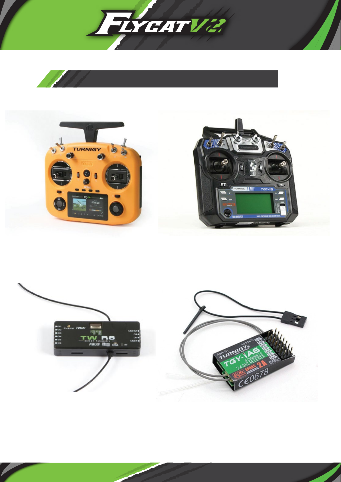
RECOMMENDED ACCESSORIES
Turnigy/FrSky TWIN X14 ACCESS
2.4GHz Transmitter (Orange)
SKU: 9236720209
FrSky TW R8 Dual 2.4GHz 8ch TW
Protocol SBUS/FBUS/S.Port Receiver
SKU: 9236720012
Turnigy TGY-i6 Mode 2 AFHDS
Transmitter and 6CH Receiver
SKU: 9114000020-0
Turnigy iA6 Receiver 6CH 2.4G AFHDS
2A Receiver
SKU: 9114000008-0
Recommended Accessories
19
Page 21

RECOMMENDED ACCESSORIES
Turnigy Heavy Duty 4000mAh 6S
60C Lipo Battery Pack w/XT90
SKU: 9067000386-0
Turnigy Heavy Duty 3300mAh
6S 60C LiPo Pack w/XT-90
SKU: 9067000242-0
Turnigy Graphene Panther 5000mAh
6S 75C Battery Pack
SKU: 9067000375-0
Turnigy Graphene 4000mAh 6S 45C
LiPo Pack w/XT90
SKU: 9067000146-0
Turnigy Nano-Tech Plus
3000mAh 6S 70C Lipo Pack w/XT90
SKU: 9210000266-0
Turnigy 4500mAh 6S 30C Lipo
Pack w/XT-90
SKU: 9067000272-0
20
Page 22

RECOMMENDED ACCESSORIES
ToolkitRC M6DAC Dual 1~6S 15A 350W
AC/DC Balance Charger/Discharger
UK Plug SKU: 9989320005
US Plug SKU: 9989320079
HOTA P6 2 x 300W 1~6S Dual
Smart Charger/Discharger (DC Only)
SKU: 9466000021-0
HOTA H6 Pro AC/DC 200W
AC/700W DC 1~6S Smart Charger
US Plug SKU: 9466000020-2
SKYRC IMAX B6 V2 60W 6A 1~6S
DC Charger/Discharger
SKU: 9052000152-0
20
Page 23

 Loading...