

Page 1
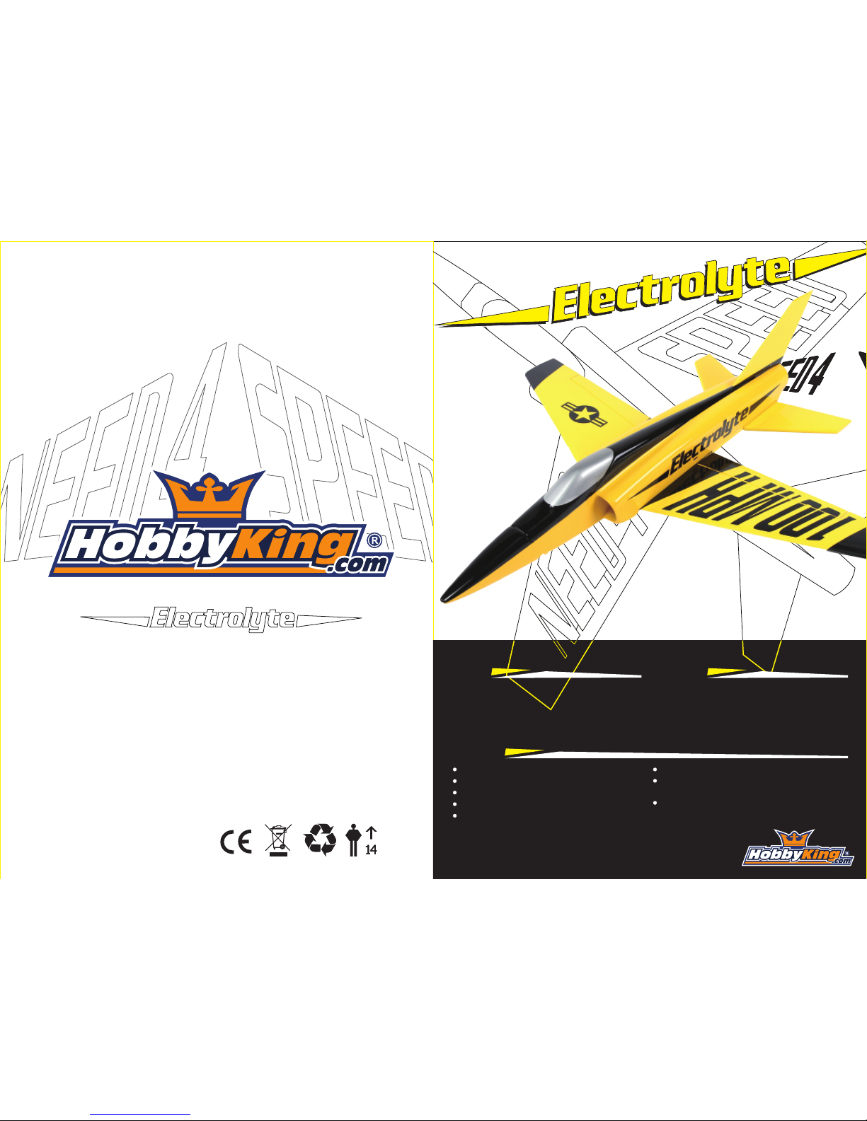
Wingspan: 508mm
Length: 533mm
Weight: 280~330g
Motor: 2040 Inrunner 8000Kv
4 Channel Transmitter and Receiver
3S 11.1V 850~1300mAh Lipoly Battery
3 x Dymond D4.7g Servos
30A Brushless ESC
Specs Required
Features
Pre-painted molded fiberglass fuselage
Balsa wing and tail from the factory
Bifurcated inlet ducting pre-installed
High visibility color scheme
Full Flying Horizontal Stabilizer
Choice of two different vertical fins included
Dr. MadThrust alloy fan shroud with 8000kV
motor included
Easy access battery hatch
Page 2
Warnings
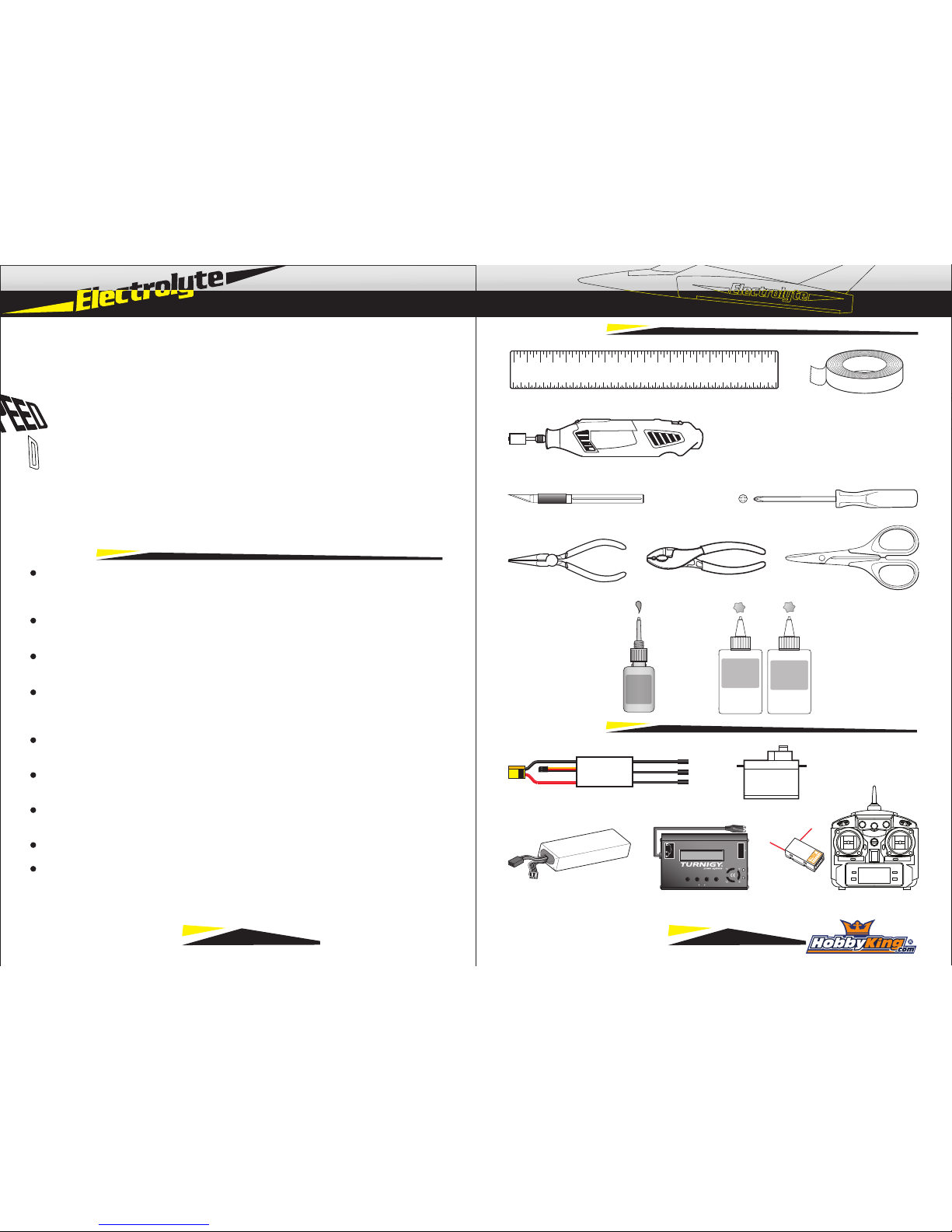
Required Items
Phillips Screwdriver
MAIN MENU
STOP ENTER
DECREASE INCREASE START
STATUS
DC
11-18V
2 CELL
3 CELL
4 CELL
5 CELL
6 CELL
Turnigy Charger
Tools Required
PliersNeedle Nose Pliers
3S 11.1V 850~1300mAh LiPo LiPo Charger
Select your flying area carefully. Always choose an open space that is unobstructed
from trees, buildings, and away from crowded areas. Avoid flying in areas with roads,
electric or telephone wires, or close proximity to full size air traffic.
Do not fly this model in poor weather including high winds, low visibility, rain, or
thunderstorms.
Never attempt to catch this model whilst in flight. Even a slow moving model can
cause harm to yourself or others.
This model is recommended for children no younger than 14 years old. All children
should always be supervised by a capable and responsible adult when operating this
model.
Always unplug your model battery when not in use. Do not leave the battery installed
in the model when not in use.
Remain clear from the propeller at all times when the flight battery is connected. A
spinnginpropeller can cause bodily injury.
Before flying always turn ON your transmitter first, then connect your flight battery to
the model.
After flying, always disconnect your flight battery first, then turn OFF your transmitter.
Always exercise caution when charging batteries. Follow the recommended charging
instructions from your battery manufacturer, and use a charger with charging parameters that match your battery type.
Thank you for purchasing your HobbyKing Electrolyte 40mm EDF. We hope you enjoy
assembling and flying it as we did creating it. Designed by Dr. Bret Becker, the Electrolyte has received a good following with members of the RC Groups forum community.
First conceived in 2010, the design featured a fiberglass fuselage, solid balsa wings,
and is powered by a 40mm micro EDF power system. It can reach speeds in excess of
100 miles per hour right out of the box.
HobbyKing aircraft follow an extensive design, development, and testing process to
bring reliable and user friendly products to the masses. They undergo extensive quality
control checks at the factory.
Please read this instruction manual thoroughly before assembling and flying this model.
It is not a toy and if mistreated has the potential to inflict bodily injury or damage
property. It is your responsibility to complete final assembly, setup, and routine pre-flight
checks. Always make sure to check for any loose screws or parts, and that the airframe
is free from damage that may cause failure in flight. HobbyKing is not responsible for
any injury or property damage inflicted due to negligence in assembly or maintenance.
Hobby Knife
CA
Glue
1 2 3 4 5 6 7 8 9 10 11 12 13 14 15 16 17 18 19
4+ Channel Transmitter + Receiver
Epoxy
A
Epoxy
B
Scissors
3 x Dymond D4.7g Servos25~30Amp Brushless ESC
TGY
Ruler Clear Tape
Rotary Tool w/ Assorted Bits 1.5mm Drill Bit
1 2
Page 3
Stabilizer Assembly
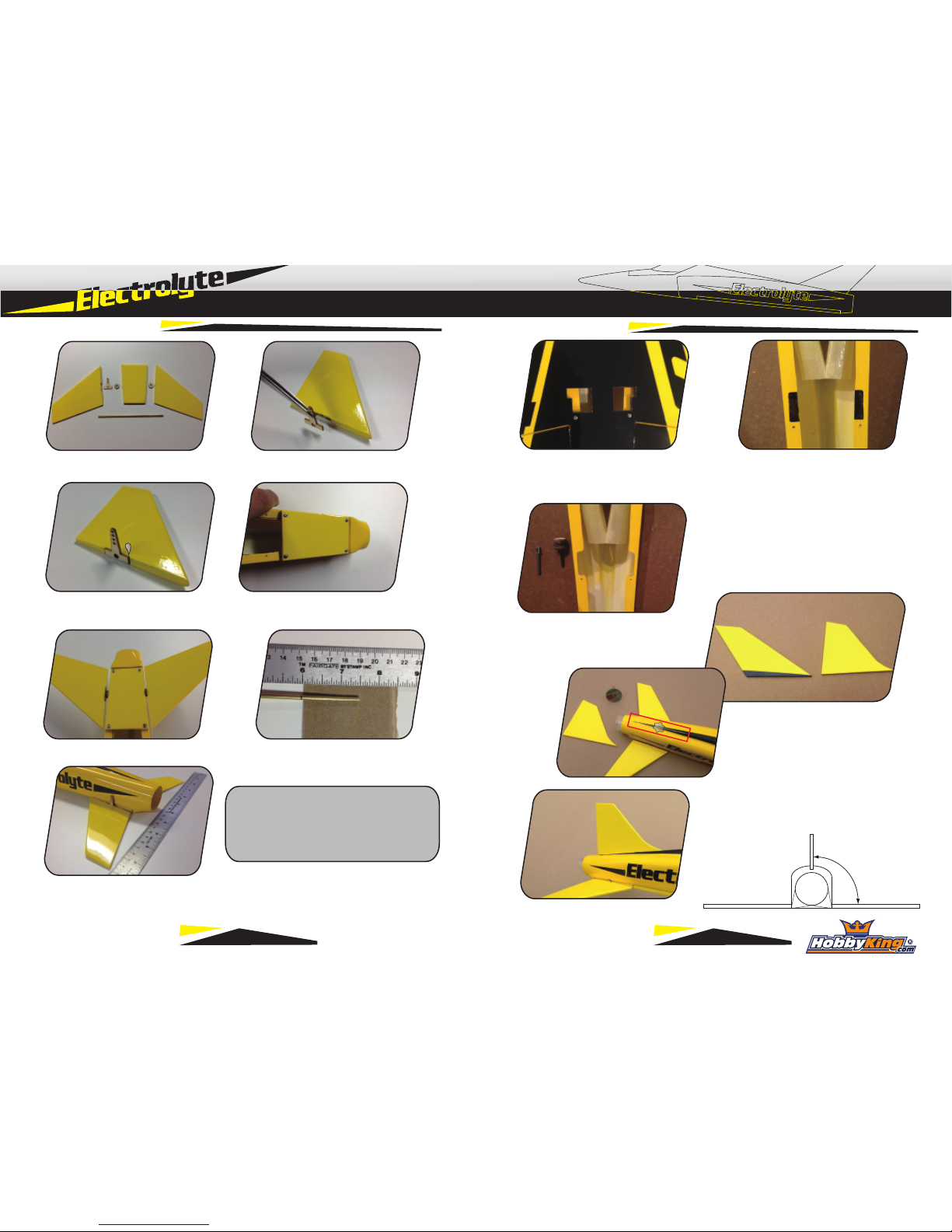
1) Identfiy left stab with recess for control horn.
2) Remove covering material where control
horn is glued to stabilizer.
3) Glue horn to stab using regular CA. 4) Attach center section of flying stab to
fuselage using 4 screws.
5) Test fit flying stab with spacers.
7) Using 15 min epoxy, glue brass tube to left stab with control horn and allow to cure. Install
left stab into center section with L & R spacers in place. Finally glue other stabilizer half. Set
on flat surface with tips of both halves contacting the flat surface for alignment.
**Build Note** Apply epoxy to stabilizer
halves only. Do not glue to center section.
Spacers should touch stabilizer slightly, but
not limit movement.
1) Locate the servo cutouts in wing and cut
away covering from the top and bottom.
2) Mount the wing to the fuselage, lining up the
wing mounting holes to the fuselage. Using a
black felt pen, mark the location for the aileron
servo cutouts in the wing saddle.
4) Select which fin option you will use.
Roughen fuselage at contact location with
sandpaper or a rotary tool.
3) Using a rotary tool, cut away wing saddle
material from the marked location. This allows
the wing servos to sit flush against the bottom
of the wing.
5) Glue fin to fuselage with 15 minute epoxy,
keeping the fin 90 degrees to the horizontal
stabilizer.
6) Roughen the area on each end of the brass tube
that will be inserted into the stabilizer half.
90°
Airframe Assembly
3 4
Page 4
Wing Assembly
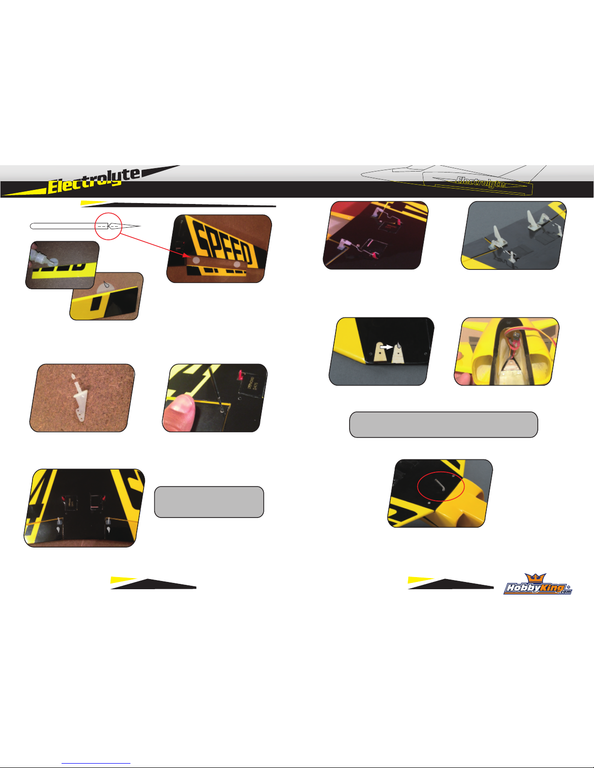
2) Trim micro aileron horn at 3rd ring (Barb)
Prevents horn from protruding through top of
wing.
3) Using a 1/16” (1.5mm) drill bit, drill a hole
manually from the underside of the aileron. Use
your finger placed on the top surface to prevent
drilling through the covering
8) Install landing skids on bottom of wing. These
are a wear item and will need to be replaced
periodically.
**Build Note** Center servos and
install control arms on servos prior
to gluing into wing.
4) Glue micro control horns to bottom of wing,
and aileron servos to wing using thick CA.
5) Install micro pushrods. Suggest placing the
U-bend towards the wing surface to prevent
catching upon landing.
1) Use two hinges per aileron. Check that there are slots for hinges. Cut slots as necessary with a
sharp hobby knife.
Glue hinges first to aileron with thin CA. When dry, glue to wing, checking for even gap on aileron
ends to ensure free movement.
6) Mount Bungee hook block by removing covering from top of the wing in shape of bungee
hook block. Block should be even with front of wing. Glue in place with Epoxy.
**Build Note** Mount may need to be tapered to properly
clear the ducting. Check fit before gluing to the wing.
7) Screw in bungee hook from bottom. Hole may
need to be drilled out for proper fit. A dab of epoxy
can be used to further secure hook to block.
5 6
Page 5
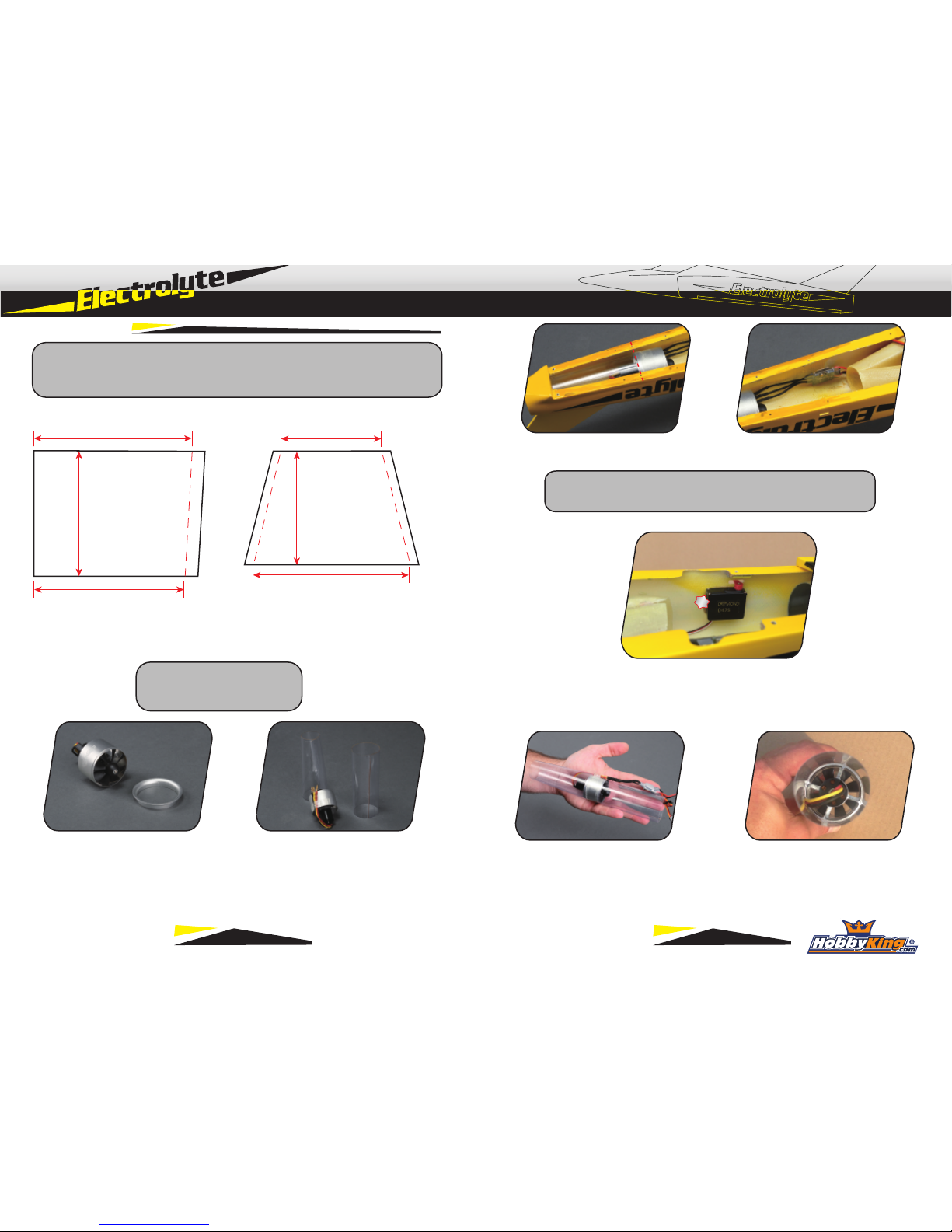
Fan Installation
**Build Note** The performance of this model lies in attention to detail when
installing the ducting. The templates below are rough estimates and may need
slight adjustments to fit your exact model since each one is slightly different.
1) Using the templates above as guides, cut front and rear ducting pieces from the included
clear plastic sheet. Each template above has excess material shown (beyond the dashed line)
that helps to make taping the ducting together easier. Suggest 10mm for forward duct, and
8mm each side of rear duct.
Forward Duct Rear Duct
2) Remove front lip piece from fan. This
will not be used for the Electrolyte.
*Thrust Tube Exit Diameter*
- 30mm Yields optimal speed
- 33~34mm Yields better static thrust
3) Using clear tape, tape together the ducting pieces.
For tightest fit of rear ducting, roll it tightly around fan
prior to taping. Make front and rear duct pieces.
4) Test fit fan and ducting into fuselage. Back edge of fan shround will align to 3rd set of screw
holes. (From back) ESC will mount on right side of fuselage, opposite the elevator servo.
6) Using clear tape, carefully attach ducting to fan to make complete unit. Check your motor
for proper rotation direction prior to installation. Route motor wires as shown, minimizing
force on the wires to prevent long term damage.
5) Mount elevator servo to left fuselage side
using 15 minute epoxy. Install servo arm and
center servo before gluing to fuselage.
120mm
104mm
138mm
132mm
137mm
100mm
**Build Note** Aft tail mount blocks in fuselage may need slight
bevel to allow rear ducting to be inserted without distortion
7 8
Page 6
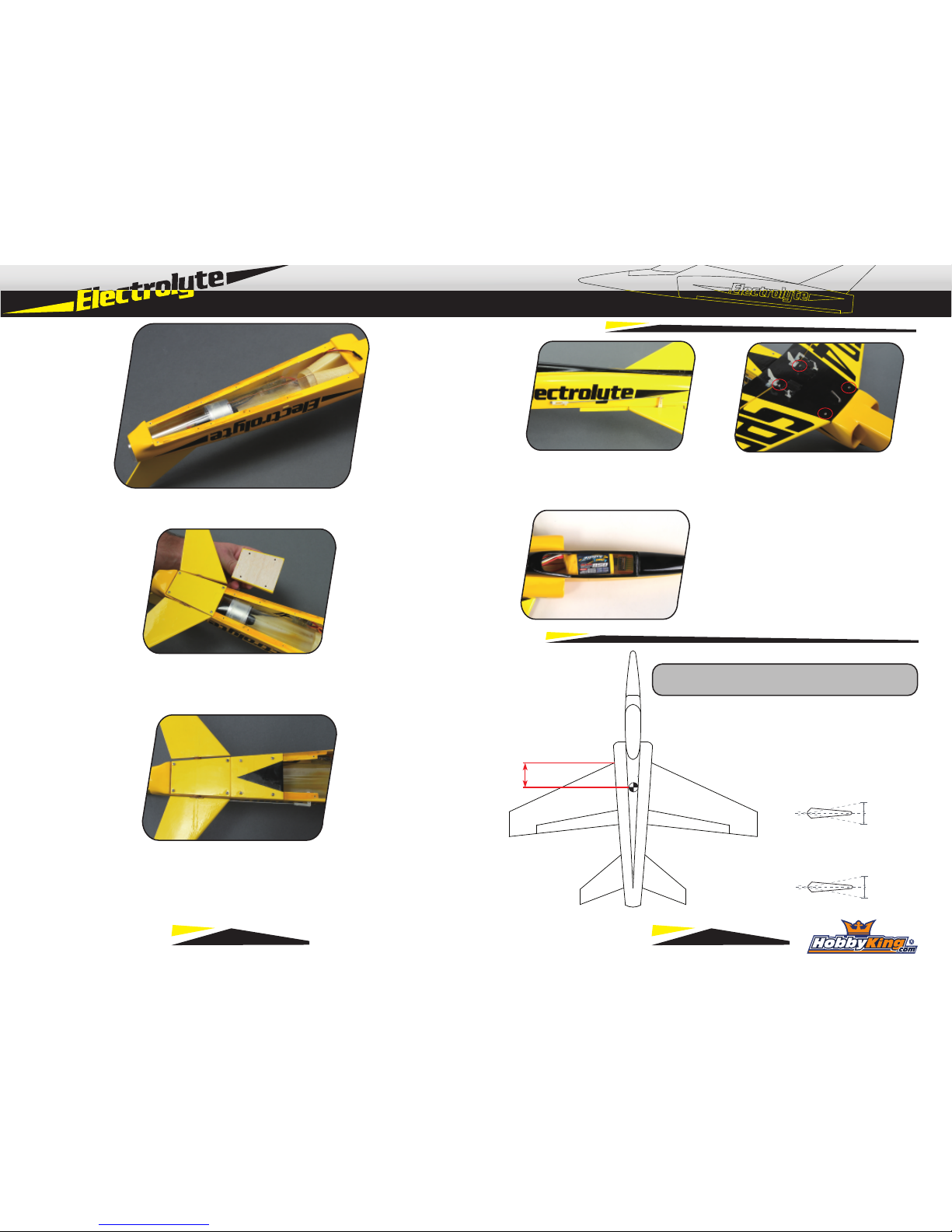
Setup
1) Attach elevator pushrod to servo and stabilizer
as shown. Secure clevis with set screw. See note
on page 11 for elevator setup.
2) Attach wing to fuselage using four screws.
Feed aileron, elevator, and ESC leads under
bifurcated inlet ducting into forward fuselage.
Elevator
2~4mm
2~4mm
Aileron
57mm (OnSpar)
5mm
5mm
3) Install receiver and battery, secure both with
velcro. Refer to final setup below for CG.
**Setup Note** 2mm aileron throw is general recommendation. 4mm is ONLY for hand launching, no Bungee.
7) Carefully insert the full fan/ducting module into the model, spreading the fuselage to slip the fan
past. Once the whole module is inserted, slide it forward overlapping by 3~4mm on front ducting.
9) Apply 15 minute epoxy thickened with microballons to fan
where it contacts the fuselage sides. High temp RTV silicone
can be used as well should you need to remove the fan later
Final Assembly
10) Hatch installed on fuselage with 4 screws
9 10
Page 7
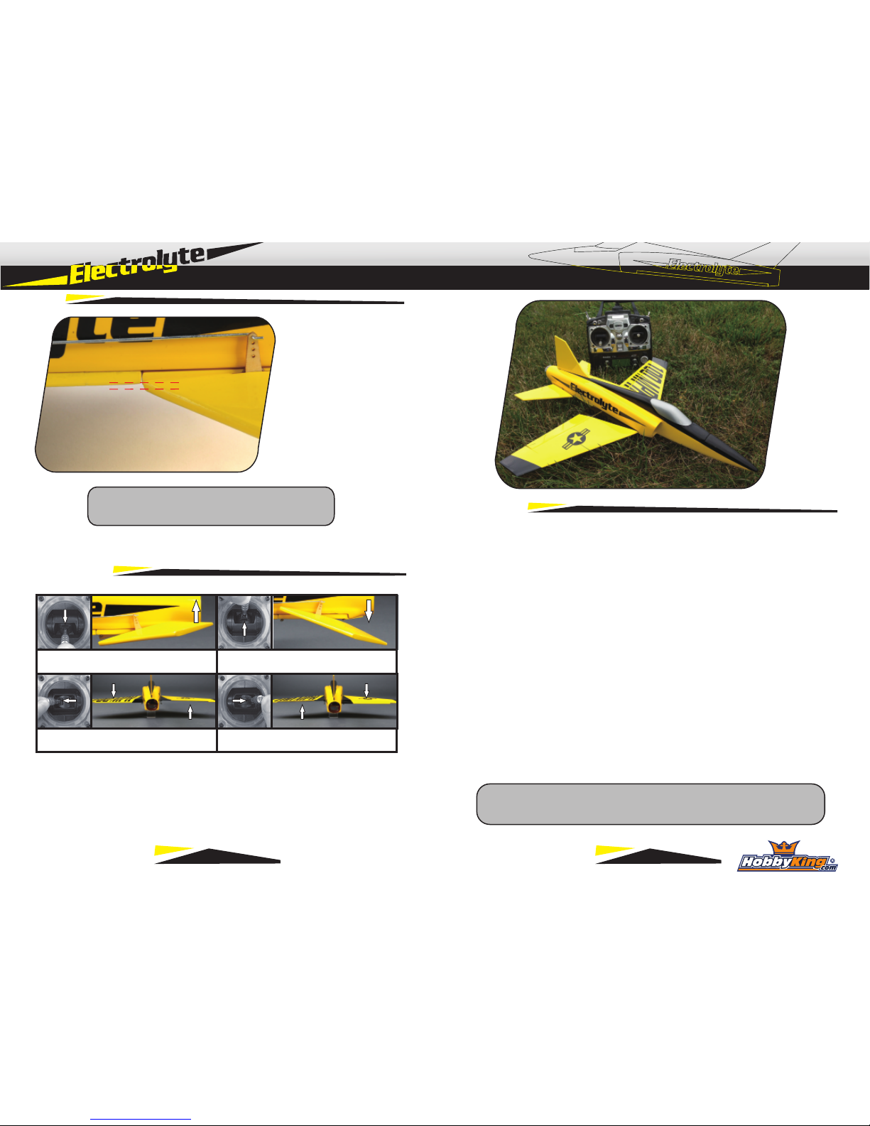
3mm
1) Before flying this model, check that the model is assembled per this manual and is
free from any damage that may have occured during transport.
2) Insert flight battery, and check for proper center of gravity. Secure battery with velcro
on the bottom of pack and velcro strap around it. If the battery shifts in flight it could
cause a loss of control.
3) Ensure that pushrods and control surfaces move freely with no binding. For best
results, disconnect pushrods and flex the hinges by hand to free up the hinges.
Reconnect control rods prior to first flight.
4) After turning on the transmitter and then connecting the flight battery, perform a full
range test, and then check control direction per the guide on previous page.
5) Conduct a full power test.
6) Inspect your flight location, making sure it is free from trees, vehicles, people, or
other obstructions before taking off.
7) For bungee launching, stake bungee line into ground. Pull all slack from line, then
walk additional 17~20 paces. This provides good launching power
8) Apply about 3/4 power, nose up, about 60~75 degrees, and let go. Do not push.
Up Elevator Down Elevator
Left Roll
Right Roll
**Launch Note** Wind direction is very important for a successful
bungee launch. Cross wind launches are to be avoided at all cost.
**Setup Note** Set elevator neutral with small amount of
up elevator. Center leading edge of stabilizer with
bottom of the fuselage. This is approximately 3mm.
Control Check
First Flight
Setup
11 12
 Loading...