

Page 1
INSTRUCTION MANUAL
Page 2
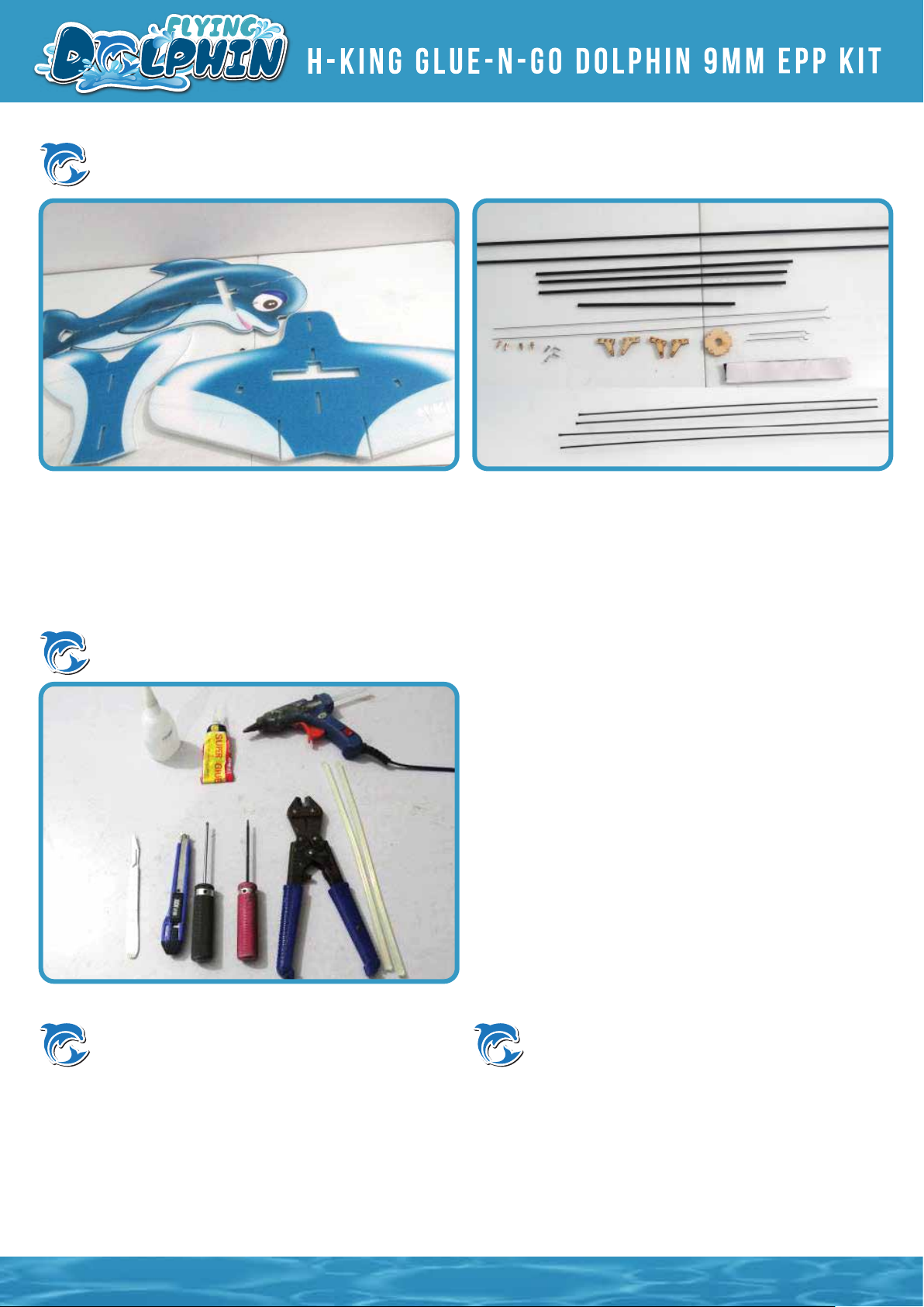
Packing list
1. PP Dolpin Fuselage
2. Carbon Tube 5x x 940mm x 1pc
3. Push rod x 4 pcs
4. Motor mount x 1
5. Quick push rod adjuster x 4 pcs
Tools
6. Plywood control horn x 4 pcs
7. M3 self tapping screws x 4 pcs
8. Hook and loop double sided tape
9. carbon strips x 6 pcs
10. PP sheets
1: 1.5mm allen wrench
2: Phillips screwdriver
3: Modelling knife
4: Wire cutters
5: Hot melt glue gun and glue sticks
6: Foam Glue
7: No.502 glue
8: Y cord*1
Electronic equipment
Motor:2206-2212 1400KV-2600KV*1
Prop:6×4/8×6 *1
ESC:12-40A*1
Servo:8/9g *4
Battery:500-1500mah 3S *1
Indoor Flying electronic
equipment
Motor:2205-2206 1400KV-1700KV*1
Prop:8×6 *1
ESC:10-12A*1
Servo:4.5/4.7g *4
1
Page 3
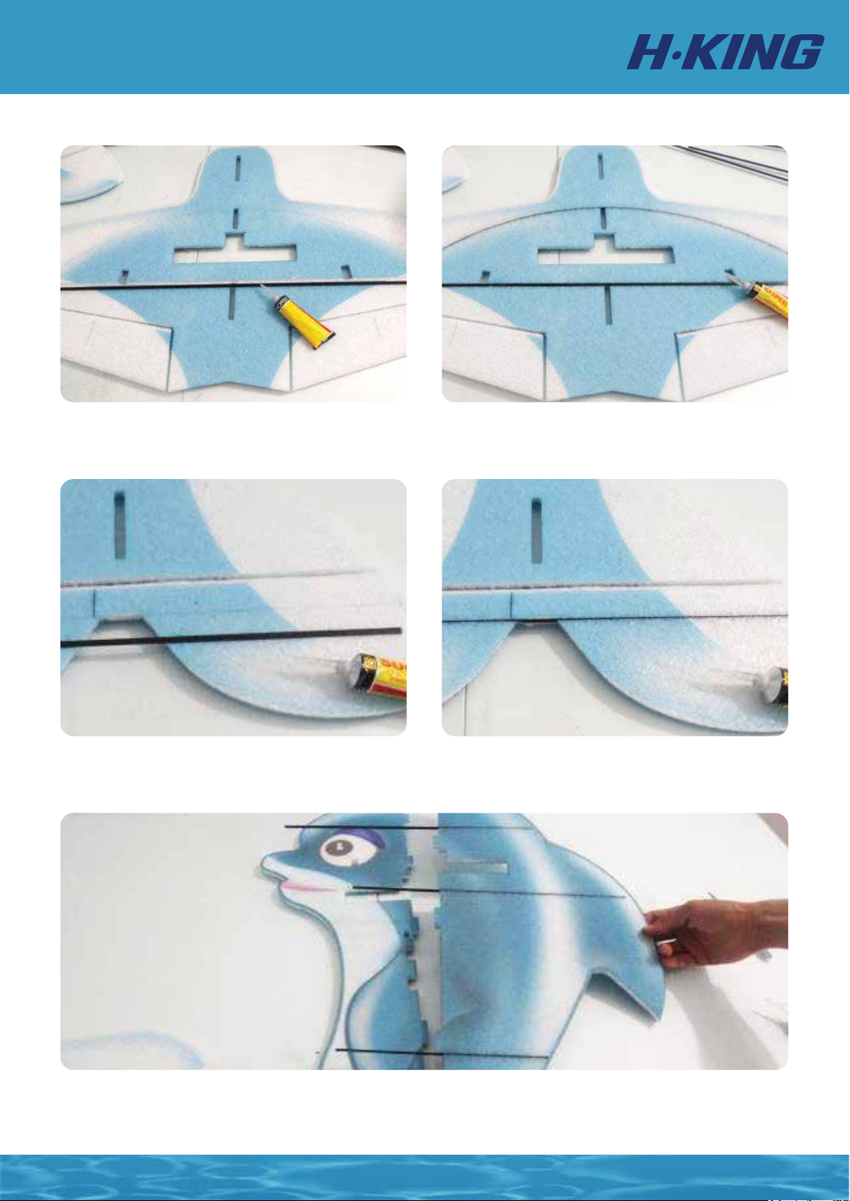
1. Apply glue to the carbon tube and install it onto the
wing.
3. Apply glue to the carbon strip and install the it to the tail as shown.
2. Apply glue to the carbon strip and install it to the slot
near the leading edge of the wing.
4. Install the carbon strips with different length according to the picture as shown. Once you have stastisfied with the
installation, apply glue to the strips and insert it into the slot on the upper body. Ensure all the carbon strips are
perfectly aligned parallel to the body. (Important: do not install the bottom half of the fuselage at this moment!)
2
Page 4
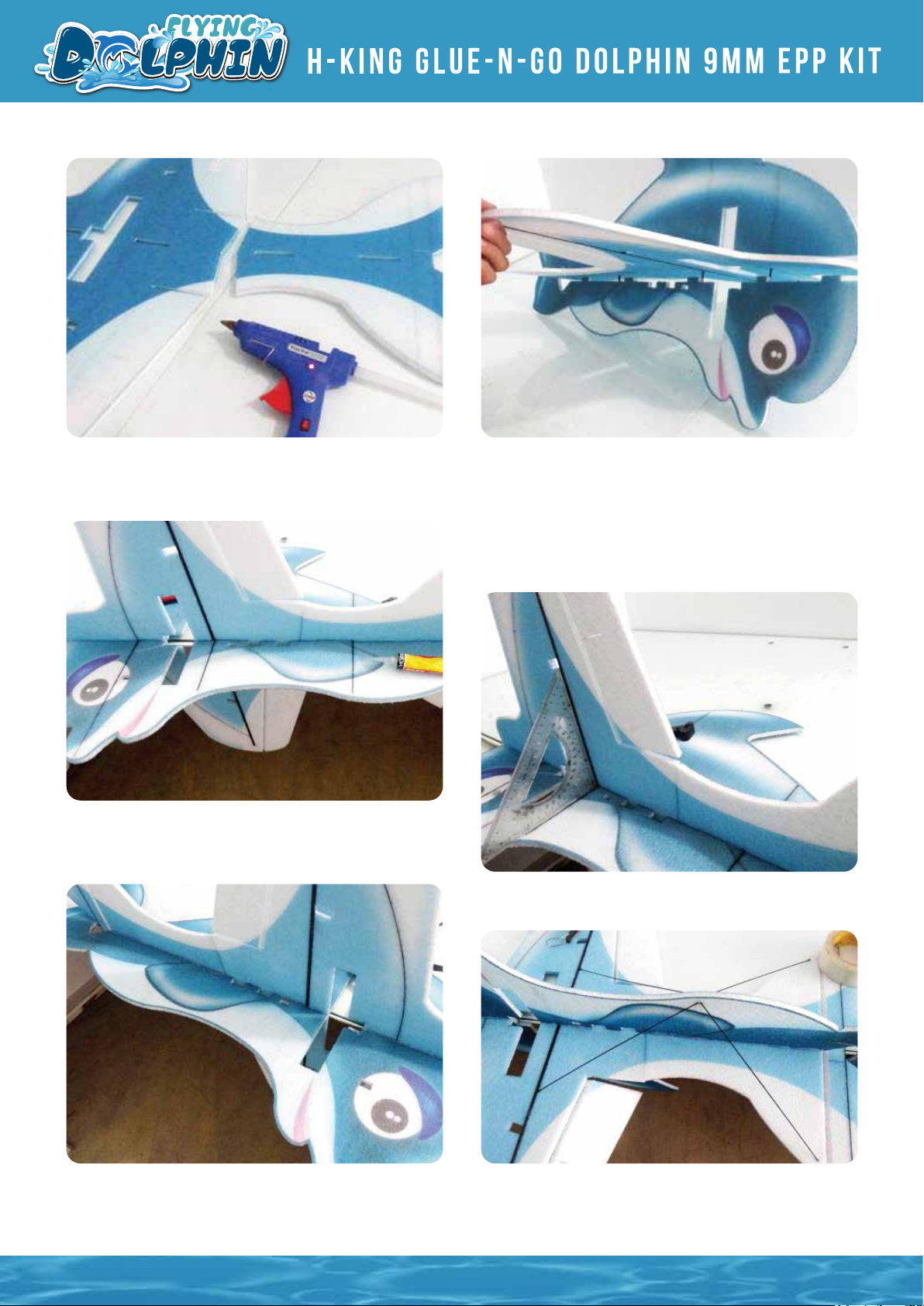
5. Glue the wing and the tail together by using hot glue.
Ensure they are perfectly level to each other when bond
together.
7. Let the glue dries. Set it aside and check the fit
frequently to ensure everything is perfectly well aligned.
6. Install the wing to the upper part of the fuselage and
at the same time, install and glue the bottom half of the
fuselage to the wing. Align the upper body with the
carbon strips to the bottom half of the fuselage. Ensure
the fuselage is perfertly flat without crooked and
misalignment. During the assemble, the motor mount
location must be flat for proper motor installation.
8. Use a straight edge to check the wing and the fuselage is perpendicular to each other.
9. Reinforce and secure all the carbon strips by using
instance glue.
10. Install 2mm x 4 pcs carbon rods as shown in the
picture. These carbon rods add strength to the fuselage
and the wing which to prevent from flexing during
flights.
3
Page 5
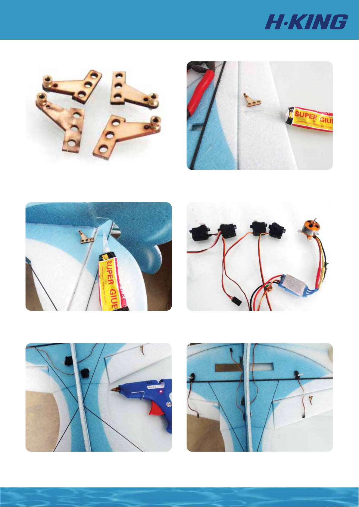
11. Assemble quick rod adjusters to the plywood control
horns.
12. Apply glue and install all the control horns to the
control surfaces as shown.
13. Prepare RC electronic components and install it
onto the fuselage.
14. Install elevator and rudder servos onto the fuselage
as shown. From the bottom view, left is the elevator
servo and right is the rudder servo.
14. Install elevator and rudder servos onto the fuselage
as shown. From the bottom view, left is the elevator
servo and right is the rudder servo.
4
Page 6
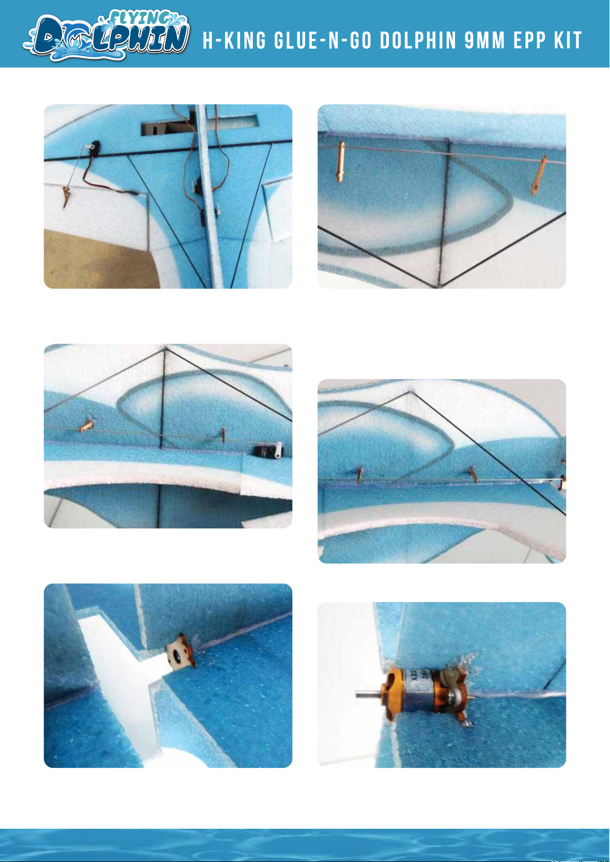
16. Install push rods onto the control horns, hook up to
the rod adjuster and tighten the grub screw when the
control surfaces are perfectly levelled.
17. Install push rod holder onto the fuselage. Align the
hole on the holder in a straight line. Thread the elevator
push rods thru the holes of the holders as shown. Try to
align the push rod to the push rod holder, servo control
horns in a straight line to make sure the rod moves
without stiction.
18. Same method applies to rudder.
19. Hot glue the motor mount onto the fuselage.
20. Install a motor mount on the plywood mount.
5
Page 7
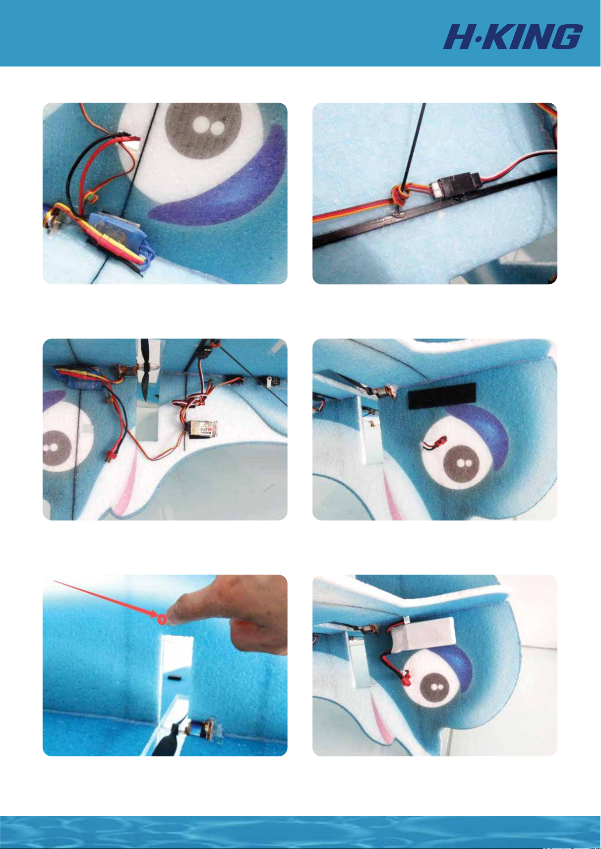
21. Use the supplied hook and loop double side tape to secure the ESC onto the fuselage.
22. Tidy up all the servo leads by cable ties to ensure it wont catch by the spinning propeller. Keep all the wires and
cables away from the spinning prop at all times.
23. Use the supplied hood and loop double sided tape to
secure the battery on the front part of the fuselage as
shown. To achieve the right C of G, Move the battery
location front/aft on the fuselage to achieve the best results.
24. The C of G is clearly marked in this instruction
manual as shown.
6
Page 8
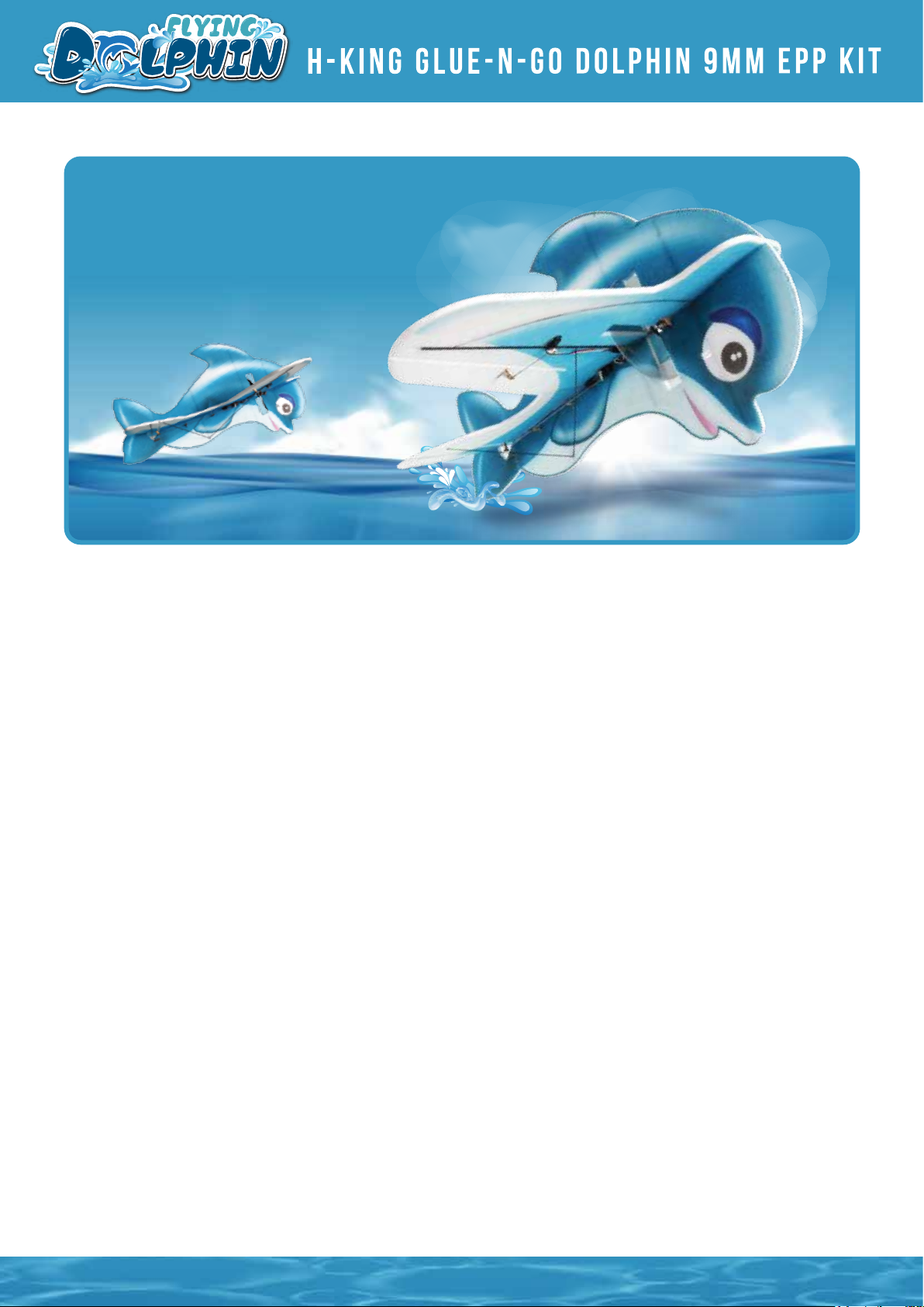
Happy Flying!
7
Page 9

 Loading...