

Page 1
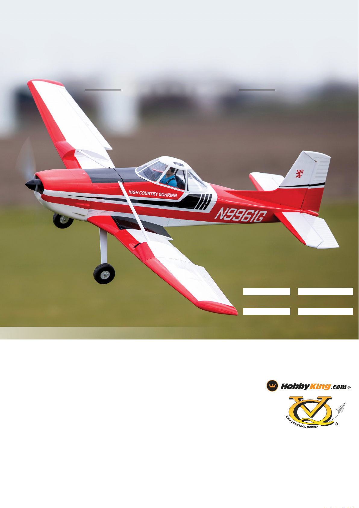
CESSNA 188
AGWAGON
SEMI SCALE MODEL
.60 CLASS
2 STROKE GLOW
.90 CLASS
4 STROKE GLOW
6S 300-400KV
ELECTRIC MOTOR
10cc CLASS
GAS ENGINE
INSTRUCTION MANUAL
SPECIFICATIONS
- Wingspan : 1920mm
- Length : 1300mm
- Electric Motor : 300-400kv (NTM 5060 380kv)
- Glow Engine : .60 2 Stroke / .90 4 stroke
- Gas Engine : 10cc
- Radio : 6 channel / 7-8 standard size servos
WARNING! This radio controlled model is NOT a toy. If modified or flown carelessly it could go out of controll and cause serious human injury or
property damage. Before flying your airplane, ensure the air field is spacious enough. Always fly it outdoors in safe areas and seek professional advice if
you are unexperienced.
ACHTUNG! Dieses ferngesteuerte Modell ist KEIN Spielzeug! Es ist für fortgeschrittene Modellflugpiloten bestimmt, die ausreichende Erfahrung im
Umgang mit derartigen Modellen besitzen Bei unsachgemäßer Verwendung kann hoher Personen- und/oder Sachschaden entstehen. Fragen Sie in
einem Modellbauverein in Ihrer Nähe um professionelle Unterstützung, wenn Sie Hilfe im Bau und Betrieb benötigen. Der Zusammenbau dieses Modells
ist durch die vielen Abbildungen selbsterklärend und ist für fortgeschrittene, erfahrene Modellbauer bestimmt.
TECHNISCHE DATEN
- Spannweiter : 1920mm
- Lange : 1300mm
- Elektroantrieb : 300-400kv (NTM 5060 380kv)
- Verbrennerantrieb : .60 2 Stroke / .90 4 stroke
- Gas Engine : 10cc
- Fernsteuerung : 6 channel / 7-8 standard size servos
1
Page 2
WARNING
Please read this instruction manual fully and become completely familiar with the features of this product
before operating. Failure to operate this product correctly could result in damage to the product, personal
property and cause serious injury. This is a sophisticated hobby product and is NOT a toy. It must always be
operated with caution, common sense and some basic mechanical ability. This manual provides instructions
as to the assembly, safe operation and maintenance of this hobby product. It is highly recommended that you
follow and read fully the instructions and warnings stated in this manual including safety, assembly, set-up and
flying guidelines in order to operate this product correctly and avoid damage or serious injury.
SAFETY PRECAUTIONS
As the user of this product you and you alone are responsible for operating it in a manner that does not
endanger yourself and others around you or result in damage to the product or property of others. This
product is operated via a radio controlled system that in some cases can be subject to interference from
sources outside of your control. Interference may result in a momentary loss of control so it is always
recommended that this product be used in a suitably open outdoors space.
• This is a radio controlled flying model and as such must always be flown with caution and care.
This is not a toy.
• The Tiger Moth is designed for intermediate to advanced pilots.
• Alway exercise great caution when using the recommended battery to power this product. For full safety notes
and operating procedures, please see information provided by your battery supplier.
• Take great care when connecting/disconnecting the battery. See battery supplier for full safty procedures.
• Never power up the model in confined spaces and always keep the prop clear of obstructions.
• This product is not a toy. Children must be accompanied by an adult at all times if operating this product.
• Only fly this model in an open area away from crowds, people, buildings, trees, power lines and obstructions.
• Always put safety first when operating this model and consider the warnings stated above.
• The supplier/manufacturer accepts no responsibility for damage or injury caused through the use of the
product. Not suitable for children under the age of 14. THIS IS NOT A TOY.
Page 3
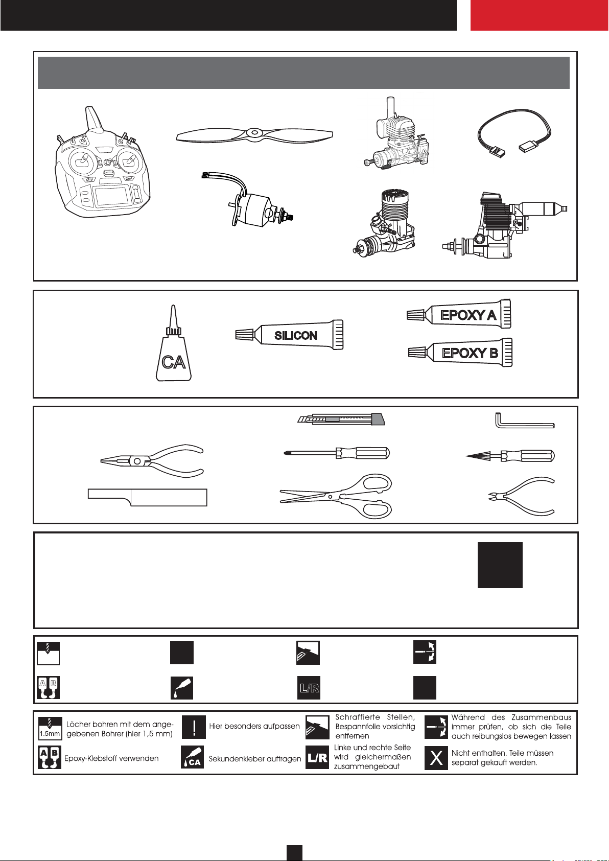
REQUIRED TO COMPLETE (PURCHASE SEPARATELY)
0.61 cu.in. (10cc)
Servoverlangerungskabel
Extension cord
Minimum 6 channel radio
for airplane
Minimum 6 Kanal
Fernsteuerung
Cyanoacrylate Glue
Sekundenkleber
Brushless Motor: NTM 5060 380kv
Brushless ESC: 70-100 amp ESC
Battery/Flugakku LEMONRC:
Turnigy NanoTech 5000mah 6S
CA
Tool Required / Erfoderliches Werkzeug
.........................................................
.........................................................
.........................................................
.........................................................
.........................................................
.........................................................
.........................................................
.........................................................
.........................................................
.........................................................
.........................................................
SILICON
Silicon Glue
Silikonkleber
.60 cu.in. (7.5cc)
Epoxy Glue (30 minutes type)
Epoxy-Klebstoff (30min)
.90 cu.in (8.5cc)
EPOXY A
EPOXY B
The pre-covered film on ARF kit may wrinkle due to variations of temperature.
Store model in a cool and dry place for awile.
Then, staring with low heat, you may carefully use a hair dryer to smooth out wrinkels.
Die Bespannung des Modells kann durch Temeratureinflusse erschlaffen oder Falten
werfen z.b bei zu starker Sonnenenstrahlung oder Hitze.
Stellen Sie das Modell zunachst an einen kuhlen Platz fur eine bestimmte Zeit. Danach
konnen Sie versuchen die restlichen Falten vorstichtig mit einem Haartrockner zu behandeln.
Drill holes using the stated
1.5mm
size of drill
(in this case 1.5 mm Ø)
A
B
Use epoxy glue
Take particular care here
!
Apply cyano glue
CA
Hatched-in areas:
remove covering
film carefully
Assemble left and right
L/R
sides the same way.
X
CONVERSION TABLE
1.0mm = 3/64”
1.5mm = 1/16”
2.0mm = 5/64”
2.5mm = 3/32”
3.0mm = 1/8”
4.0mm = 5/32”
5.0mm = 13/64”
6.0mm = 15/64”
10mm = 13/32”
12mm = 15/32”
15mm = 19/32”
20mm = 51/64”
25mm = 1”
30mm = 1-3/16”
45mm = 1-51/64”
11
!
Check during assembly that these
parts move freely, without binding
Not included.
These parts must be
purchased separately
Page 4
CESSNA 188
AGWAGON
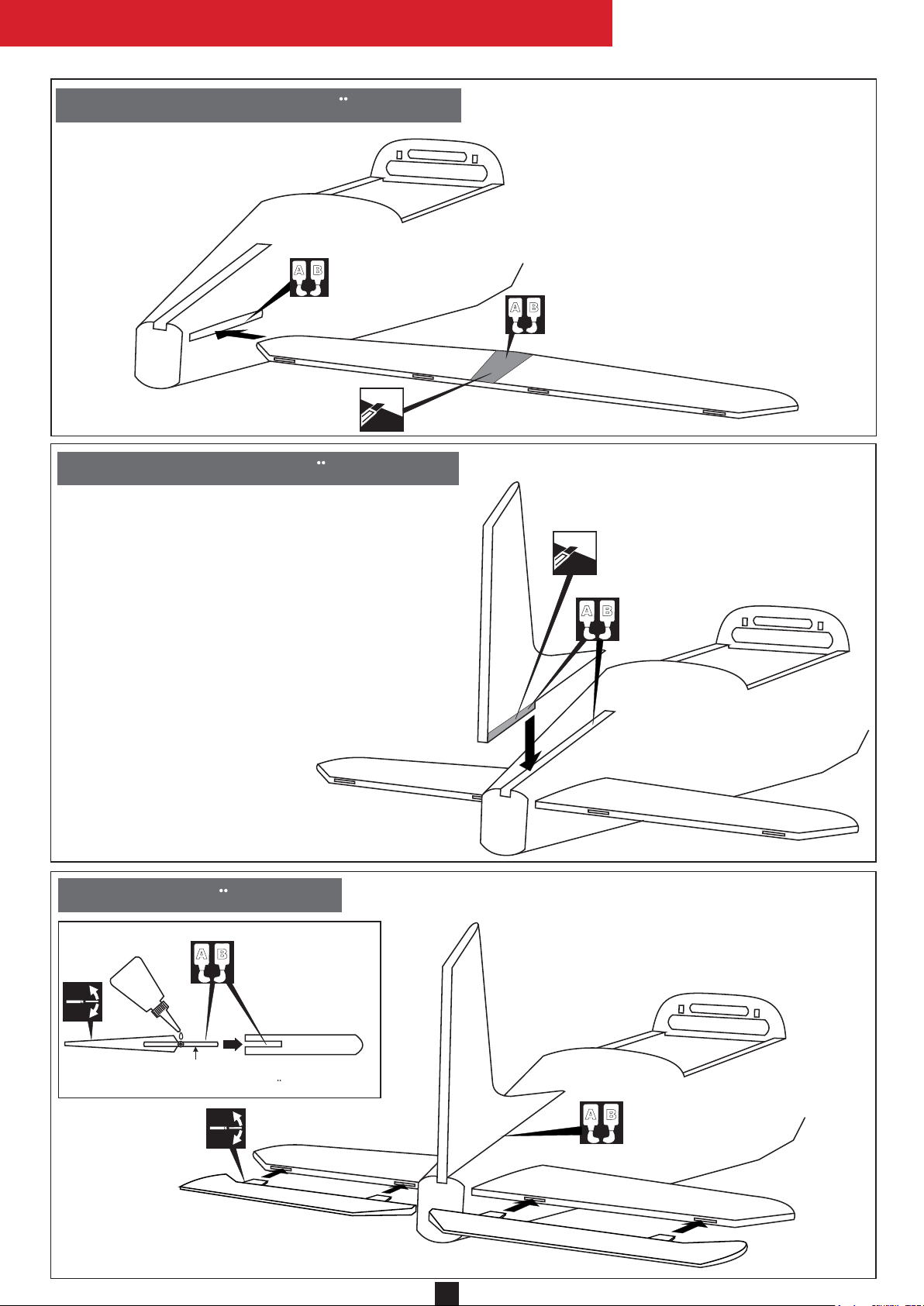
1- Horizontal Stabilizer / Hohenruder
(5 min.)
A
B
Cut away only the covering
(Both the top and bottom)
2- Vertical Stabilizer / Hohenleiwerk
Trial fit the vertical stabilizer in place on the
fuselage. Check the alignment of the vertical
stabilizer.
Using the pencil trace around the right and left
of the stabilizer where it meets the fuselage.
Remove the vertical stabilizer from the fuselage.
Remove the covering material from the gluing
surfaces on both the right and left of the vertical
stabilizer.
Spread the epoxy on the vertical stabilizer where
it contacts the fuselage and to the bottom of the
stabilizer.
Insert the vertical fin into the fuselage, ensuring
that it is seated properly on the fuselage.
Trial fit the horizontal stabilizer in place on the
fuselage. Check the alignment of the horizontal
stabilizer by measuring from a fixed point along
the center line of the fuselage to the leading edge
on each side of the horizontal stabilizer. The
distance must be equal on both sides.
Using the pencil trace around the top and bottom
of the stabilizer where it meets the fuselage.
Remove the horizontal stabilizer from the fuselage
Remove the covering material from the
gluing surfaces on both the top and bottom of the
horizontal stabilizer.
Spread epoxy onto the top and bottom of the
horizontal stabilizer where it contacts the fuselage.
A
B
Both the top and bottom
Cut away only the covering
(Both the left and right)
5 min.
A
B
Both the right
and left
3- Elevator / Hohenruder
Petroleum jelly
Hinge
Scharnier
A
B
Apply 5 min.
Epoxy both the
top and bottom.
STABILIZER
Hohenlleiwerk
A
B
2
Page 5
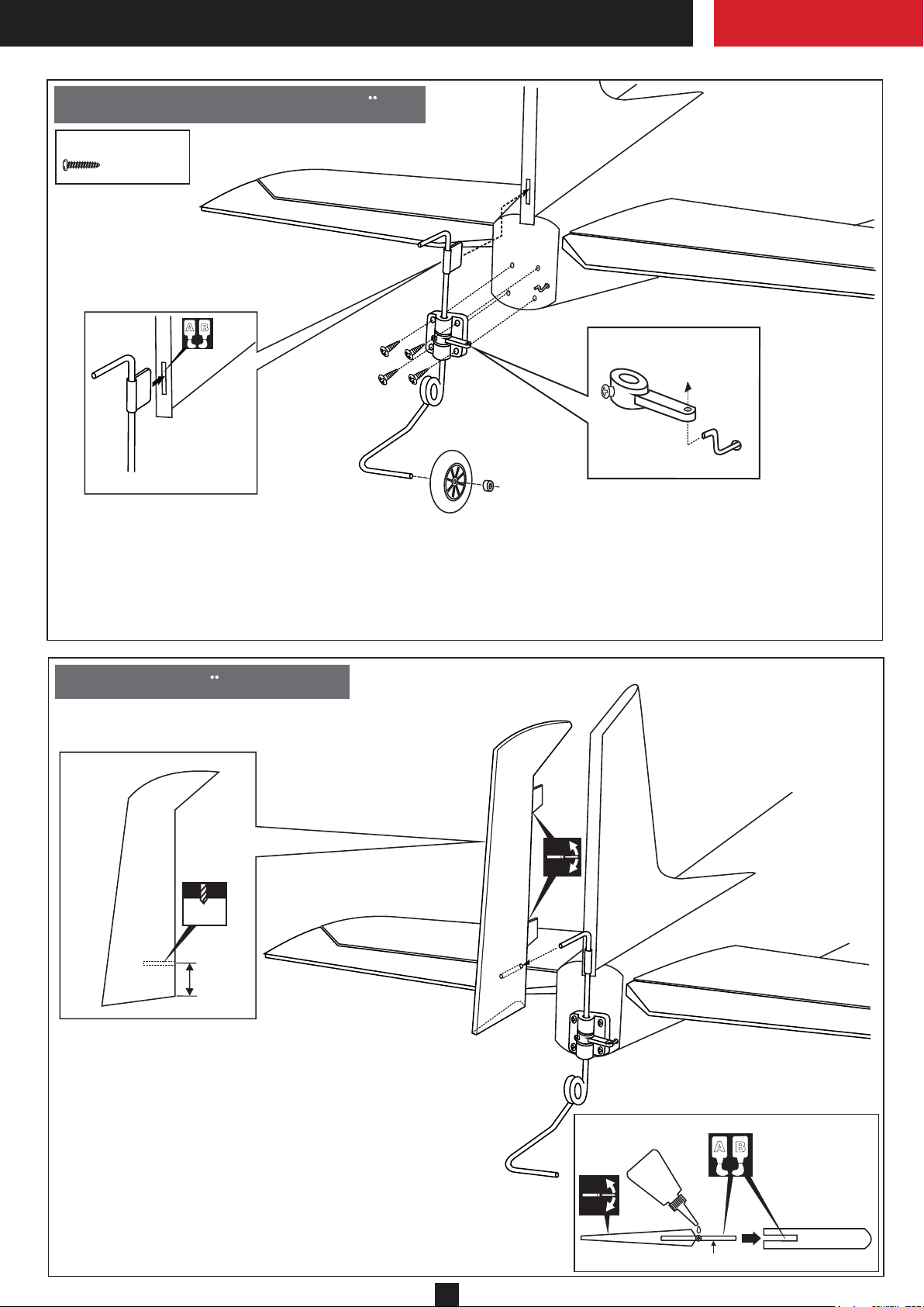
4- Tail wheel leg / Spornradtrager
3x12mm screw
...........4
Test-fit the rudder torque
rod into the slot.
NOTE: You may need to open up the slots so
that the torque rod bearing are not too difficult
to push in
A
B
3
2
1
Tail wheel control arm
1
Rudder torque rod
1- Insert the tail wheel pushrod into the hole on the tail wheel control arm (as show).
2- Re-install the rudder torque rod and tail wheel mount in place.
3- Secure the tail wheel mount in place using four 3x12mm screws.
Secure the tail wheel control horn in place using a 1/8”(3mm) screw set, Ensure smooth non-binding movement.
1
Tail wheel push-rod
5- Rudder / Hohenleiwerk
2.5mm
38mm
Drill a 3/32”(2.5mm) diameter hole in torque rod mounting slot,
marking sure that you drill the hole perpendicular to the leading
edge of the rudder.
Position each hole 38mm (+/- 1mm) out from the edge of the rudder.
Test-fit the torque rod into the rudder.
When satisfied with the fit and alignment, remove the torque rod.
Apply a thin layer of petroleum jelly to only the pivot point of the
torque rod bearing
Hinge the rudder to the vertical stabilizer, using 5 minute epoxy. Make sure
to apply a thin layer of epoxy to the left and right of both hinges and to the
inside the torque rod mounting slot and to the end of the torque rod itself.
3
Petroleum jelly
Hinge / Scharnier
A
B
Apply 5 min.
Epoxy both the
left and right.
STABILIZER
Page 6
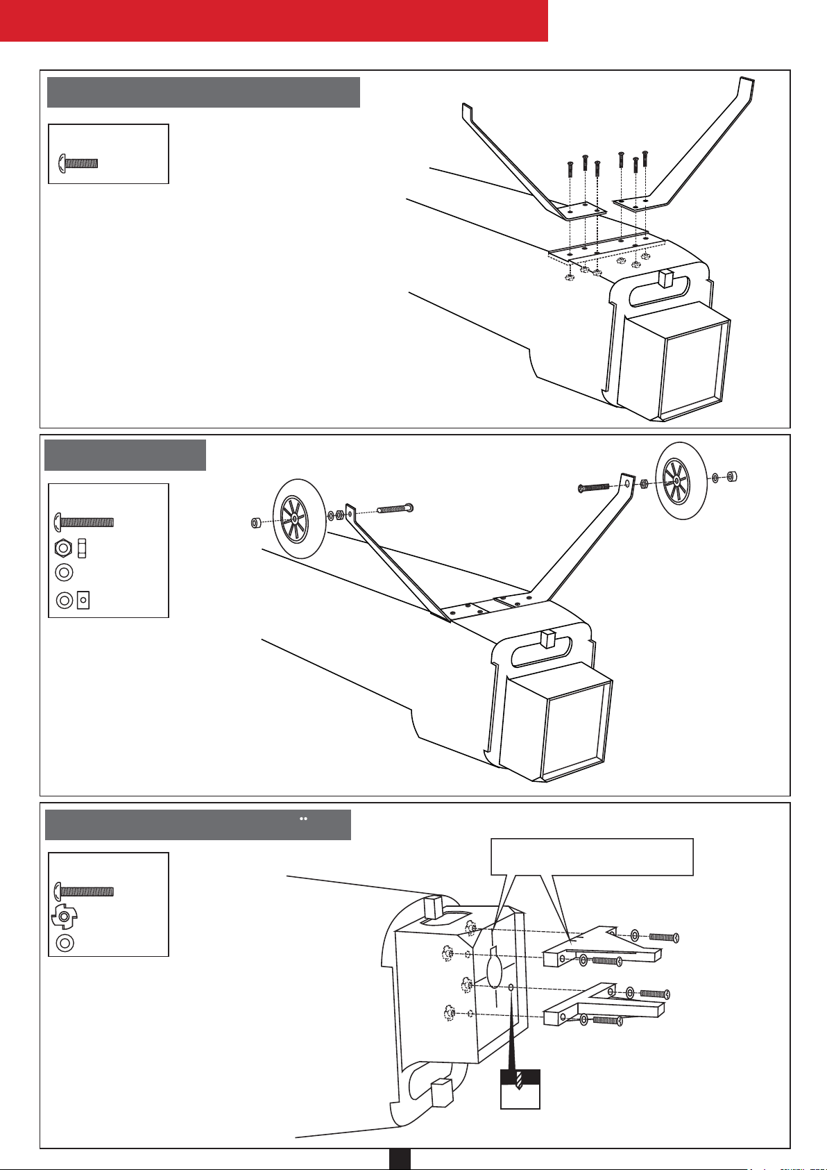
6- Main landing gear / Fahrwerk
CESSNA 188
AGWAGON
4X15mm screw
...........6
Note: All holes on the fuselage and bilnd-nuts
are pre-installed at factory.
7- Wheel / Radl
4X30mm screw
......2
Aluminum landing gear
4x15mm screw
..............2
..............2
.............2
8- Engine mount / Motortrager
4X25mm screw
......4
..............4
..............4
! Align the mark on both mounts
with the mark on the fuselage
4.5mm
4
Page 7
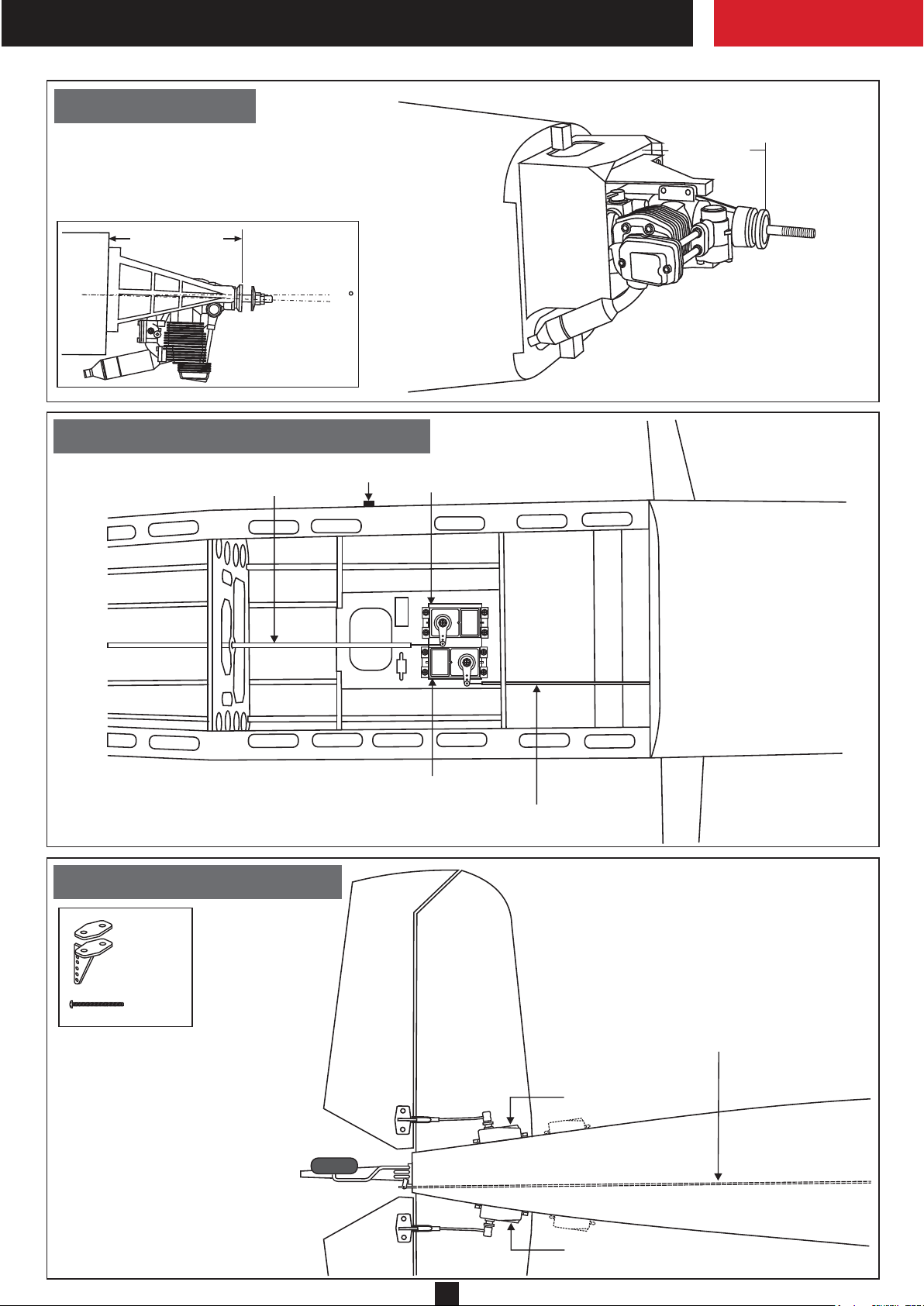
9- Engine / Motor
140-141mm
140 - 141mm
TOP-VIEW
! Engine thrust on balk
head is already adjust
at factory
10- Servo installation
Nylon pushrod guide
1.5
Switch
Rudder servo
TOP VIEW / Draufsicht
11- Linkage / Alenkungen
.........2
2x20mm
.......4
Throttle servo
Nylon pushrod guider
BOTTOM - VIEW / Unteransicht
Rudder and tail wheel pushrod
Elevator servo
Elevator servo
5
Page 8
CESSNA 188
AGWAGON
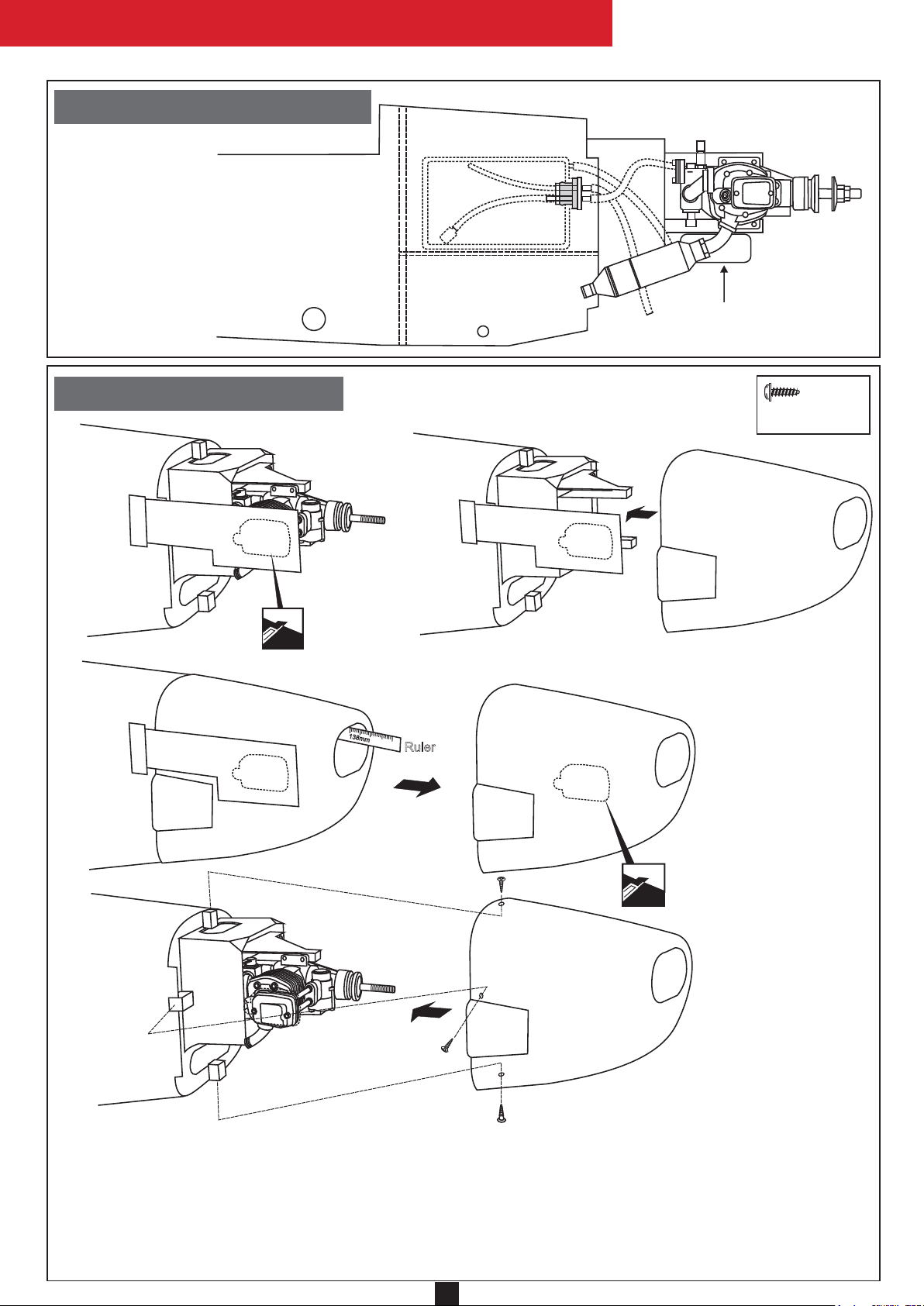
12- Fuel tank / Kraftstofftank
13- Cowling / Motorhaube
SIDE-VIEW / Seitenansicht
FUEL TANK
RECEIVER BATTERY
2.5x10mm.....4
1
3
8
m
m
Ruler
Attach the board or transparent plastic on the side of the fuselage with the adhesive tape as show.
Using a pencil or felt tipped pen trace around the engine head where it meet the cowl. Cut the opening the board or transparent plastic for the engine head as marked above.
Remove the engine and insert the cowl on to the fuselage so the distance from the fire wall to the front of the cowl is
138 to 139mm.
Remove the cowl from the fuselage and carefully cut the opening for the engine head as marked above. Do the same way
with the hole for needle-valve and silencer.
Again. Insert the cowl on to the fuselage and secure it in place with five 2x5mm screws.
6
Page 9
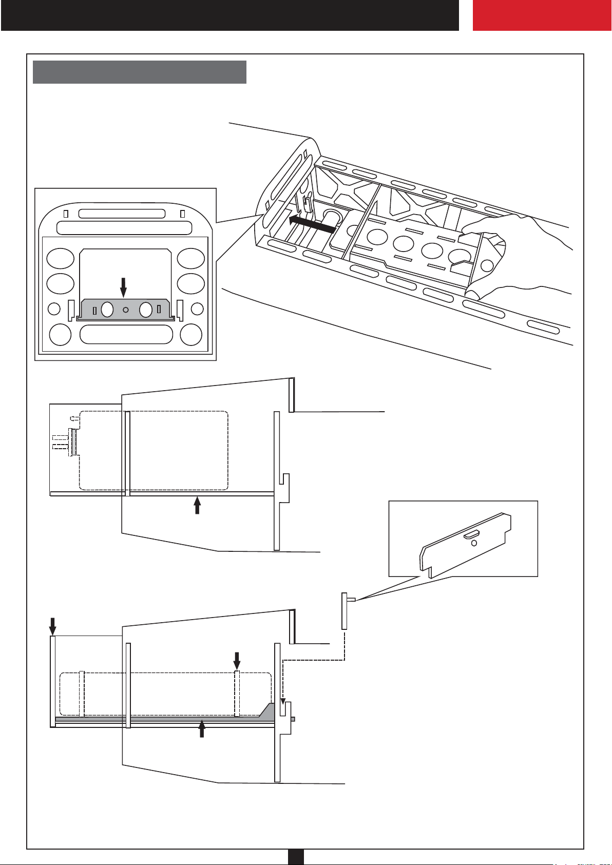
14- Li-po battery / Li-po akku
Slide the battery stand throughout the slots
on the bottom of F3
One end of the battery stand touched the
rear of the fire-wall
F3
IN CASE OF LI-PO BA TTERY USING
BATTERY STAND
Fire-wall
FUEL TANK
F2
FUEL TANK STAND
SIDE-VIEW / Seitenansicht
LI-PO BATTERY
F3A
IN CASE OF GLOW ENGINE USING
Magnetic Battery stopper
(3mm plywood)
F3
P1
Nylon cable tie
Place the Li-po battery on to the battery stand
and secure it in place with the nylon cable tie.
Slide the battery stand (P1) throughout the slots
on the bottom of F3 so that the end of the battery
stand touched the rear of the fire-wall.
F2
BATTERY STAND
Secure the battery stand in place using the
magnetic battery stopper (P4).
IN CASE OF ELECTRIC MOTOR USING
F3
7
Page 10
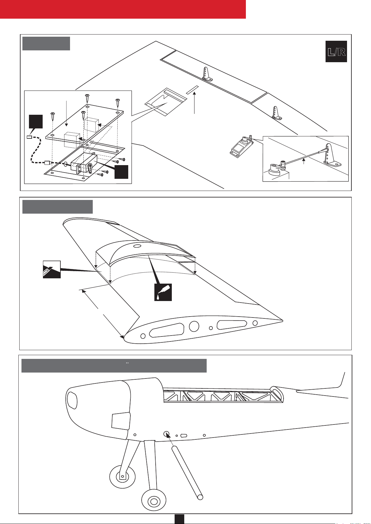
15- Servo
CESSNA 188
AGWAGON
BOTTOM - VIEW / Unteransicht
L/R
Flap servo hatch
(plywood)
X
16- ABS Shield
2x10mm
screw
X
Flap push rod exit
Aileron servo
Aileron
push rod
1-Using the ABS shield as a template, trace around the
outside edge of the ABS air-scoop,and then remove it.
2-Using a sharp hobby knife, cut away the covering inside
the lines. Not to cut into the wood.
3-Apply the ABS shield in place and secure with CA glue.
Do the same way with another half wing.
Cut away the
covering only
CA
305mm
WING - TOP VIEW
17- Wing installation / Flachenbefestigung
Insert the 18x500mm aluminum
tube throughout the fuselage
(do not using glue)
8
Page 11
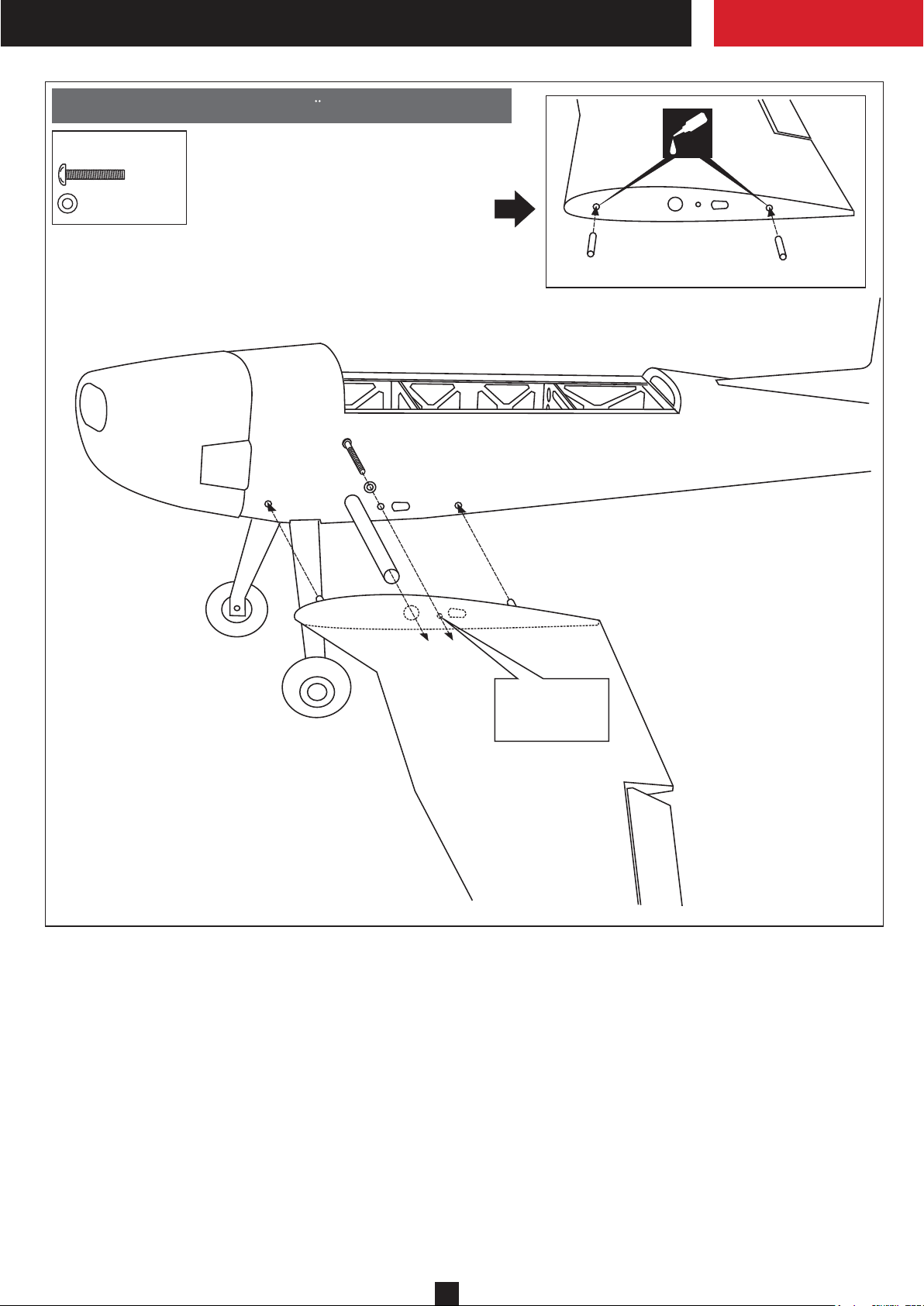
18- Wing installation / Flachenbefestigung
5X20mm screw
......2
..............2
1- Test-fit the dowel into the hole.
2- Secure the dowel in place
using CA glue.
Do the same way with another
haft wing.
5x20mm screw
5mm washer
CA
Wood dowel
Lightly, push the half wing
to the side of fuselage.
Wood dowell
Secure the half wing in place
using 5x20mm screw.
Do the same way with another
half wing.
5mm blindnut
pre-installed
inside.
9
Page 12
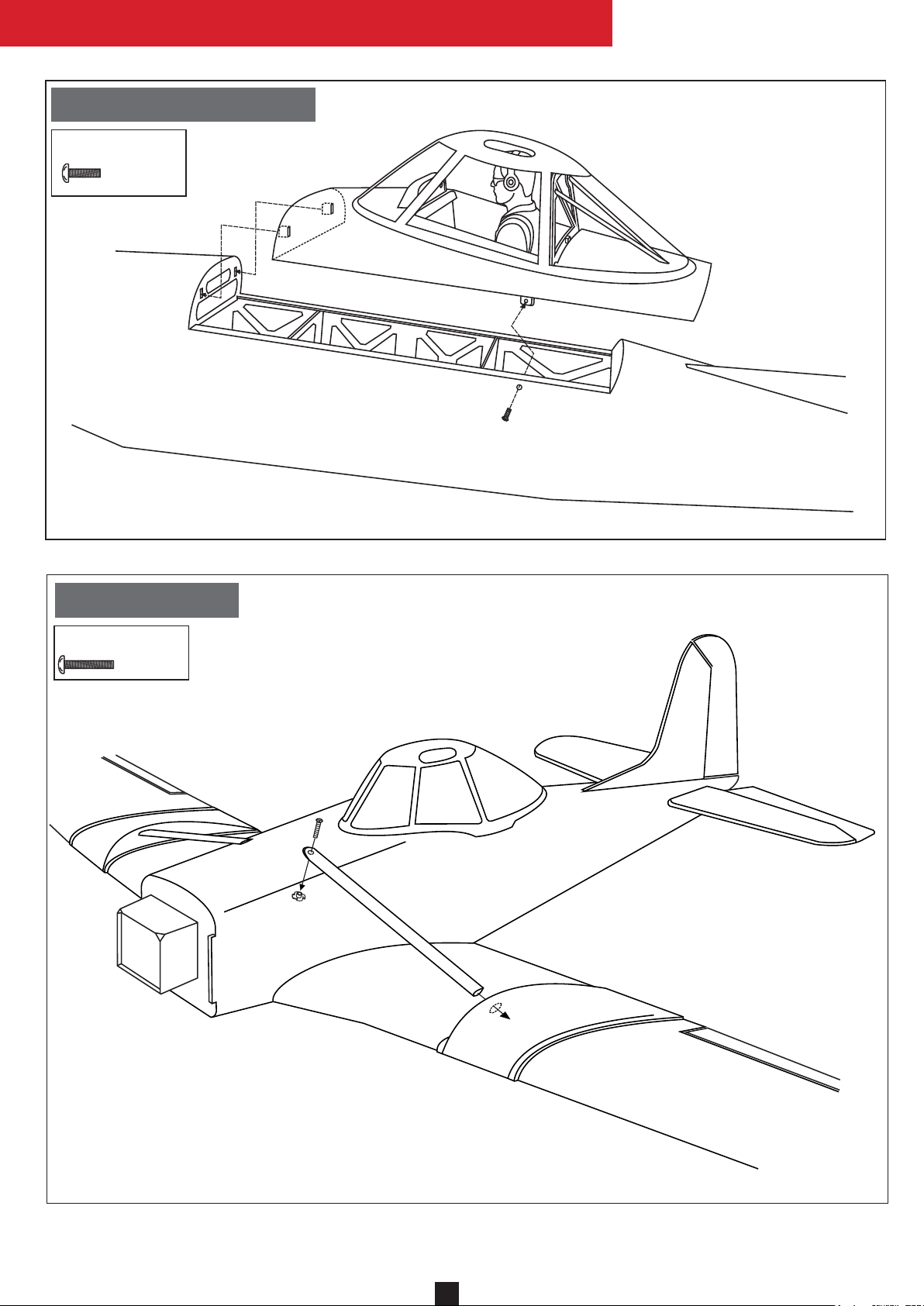
19- Cockpit installation
3X15mm screw
...........2
3x15mm screw
CESSNA 188
CESSNA 188
AGWAGON
AGWAGON
20- Wing brace
3x15mm
..........2
10
10
Page 13
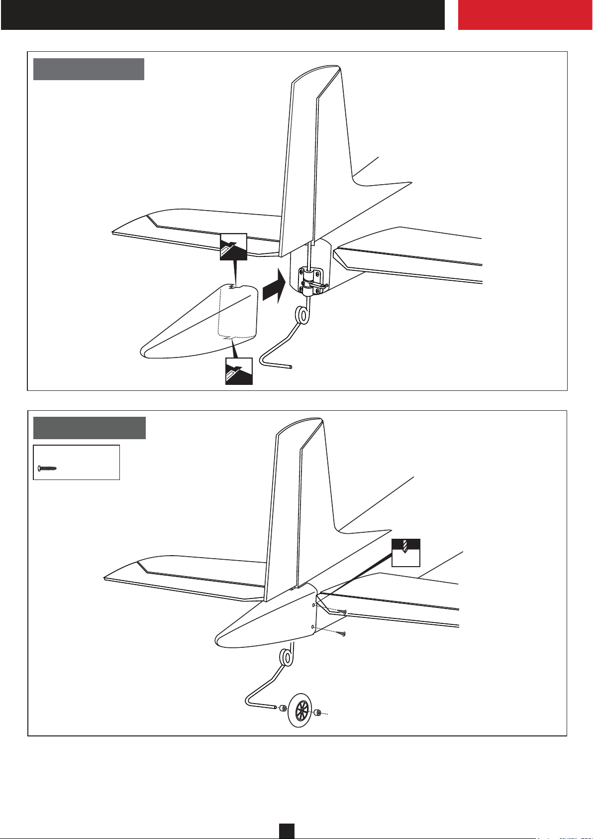
21- Tail shield
Fiberglass shield
22- Tail shield
3x10mm screw
...........4
2mm
3x10mm screw
11
Page 14
CESSNA 188
AGWAGON
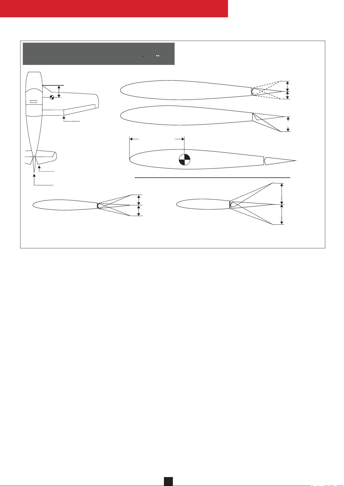
26- Control surface & Balance
Schwerpunkt & Ruderausschlage
Position for
right diagram(CG)
Position for
right diagram.
Position for right diagram.
Position for right diagram.
NEVER FLY BEFORE CHECKING THE CG’S REQUIRED POSITION.
40mm
40mm
AILERON CONTROL RANGE
FLAP CONTROL RANGE
145 - 150mm
Adjust the travel of each control surface to the
values in the diagrams these values fit general
flight capabilites. Readjust according to your
needs and flight level.
12mm
12mm
35mm
CG
80mm
80mm
ELEVATOR CONTROL RANGE
Shift the location of the battery pack as needed to obtain the specification.
Carefully install the battery pack to ensure that they will not shift during flight.
IMPORTANT :
Please do not clean your model with pure alcohol, only use liquid soap with water or use glass cleaner
to clean on surface of your model to keep the colour not fade.
RUDDER CONTROL RANGE
All details are subject to change without notice !
Technische Anderungen und Irrtumer vorbehalten !
12
Page 15

Made in Vietnam
 Loading...