

HobbyGrower Enthusiast6""x8, Enthusiast PC Greenhouse 6""x8 Assembly Instructions Manual
ASSEMBLY INSTRUCTIONS
ASSEMBLY INSTRUCTIONS
(Internal Dimensions)
Ent Spec Edition Ltr v2-0-4
Overall dimensions including base:
247.4 L x 193 W x 210 H cms
97.5" L
x 76" W x 82.7" H
Please read these instructions carefully before you start to assemble this greenhouse. To save time and
ensure proper assembly, follow the step-by-step instructions carefully in order. Assembly is easiest when
at least two people are present. Keep these instructions in a safe place for future reference.
An updated and/or improved version of this assembly guide may be available for download from the
HobbyGrower web site. Also, if you would like to view a brief general assembly video to gain a basic
understanding of how the structure is constructed, visit
http://www.hobbygrower.com, then click on the Assembly tab.
IMPORTANT!!!

SAFETY ADVICE
•Do not attempt to assemble the greenhouse in
windy or wet conditions.
•Take special care not to touch overhead power
cables with aluminum profiles.
•Ensure that there are no buried pipes or cable in
the ground before inserting the ground stakes.
•Always wear shoes and saftey goggles during
assembly.
•We strongly recommend the use of work glove
during assembly as aluminum profiles may have
sharp edges.
•Dispose of plastic bags and protective poly film
covers safely - keep them out of reach of small
children.
•The greenhouse must be positioned and anchored
on a flat, level surface.
GENERAL ADVICE
•Before beginning the assembly process, confirm
that all necessary parts have been included in the
package. It is advisable to lay the parts out in an
orderly fashion according to the part numbers so
that parts can be easily identified during the
assembly process. If parts are missing, contact
SPS International at (800) 994-5626.
•This is a multi-part assembly. Allow at least 4 hours
to assemble from start to finish. Do not begin
assembly if heavy winds or rains are expected
within 10 hours.
•Choose a sunny level location for your greenhouse,
away from overhanging trees.
•You can opt to use the base brackets supplied to
anchor your greenhouse to a concrete floor, or you
can use the base supplied base kit (see steps 36
through 38). If you intend to anchor your
•Do not lean on or push against the greenhouse
during construction.
•Keep children away from assembly area - the
aluminum profiles may have sharp edges.
•Do not position your greenhouse in an area
exposed to heavy wind.
•Do not attempt to assemble the greenhouse if
your are tired, have taken drugs or alcohol or if
you are prone to dizzy spells.
•If you use a step ladder, carefully follow the
manufacturer's instructions.
•Hot items such as recently used grills,
blowtorches, etc. must not be stored in the
greenhouse.
greenhouse directly to concrete, you must
purchase separately concrete anchor screws for
use with part number 24 anchor brackets. The area
required for the greenhouse including anchor
brackets is 104.5" (266cm) length x 83" (212cm)
width.
•It is advisable to use lubricant to ease the
connection between aluminum profiles and panel
(a mild soap and water solution is useful for this).
•Note that the door is permanently hinged on the right
hand side and therefore opens out and to the right.
•We strongly advise that you keep the special polyfilm protective covers on the side panels and the
first row of roof panels until that greenhouse is fully
assembled. You should however remove the polyfilm prior to installing the very top roof panels.
•Keep roof clear of snow and leaves.
CARE & MAINTENANCE
•Use mild soap and water and a soft cloth to wash
greenhouse glazing panels. Rinse with cold water.
•Do not use acetone, abrassive cleaners or
sponges, or other amonia-based cleaners to clean
the clear panels.
•Some chemicals and cleaners can be agressive to
TOOLS & EQUIPMENT REQUIRED
•100% "Silicone" Sealant
(compatible w/polycarbonate)
•Tape measure
•Work gloves
•Plastic or rubber mallet
the clear panels, which are made of polycarbonate.
For a complete list of chemical compatibility, visit:
http://www.spscorp.com/compatibility
•To purchase replacement parts, contact customer
service at SPS International at (800) 994-5626, or
send an email to sales@spscorp.com.
•Crosshead Screwdriver
(a.ka. "Philips")
•Lubricant (mild soap & water
solution works well)
•Scissors
1
See next page for complete list of parts
•Step ladder
•Level
•Large Hammer (for anchor stakes)
•5/64" Drill bit
(or similar diameter nail)
2
1
2
3
4
5
6
8
9
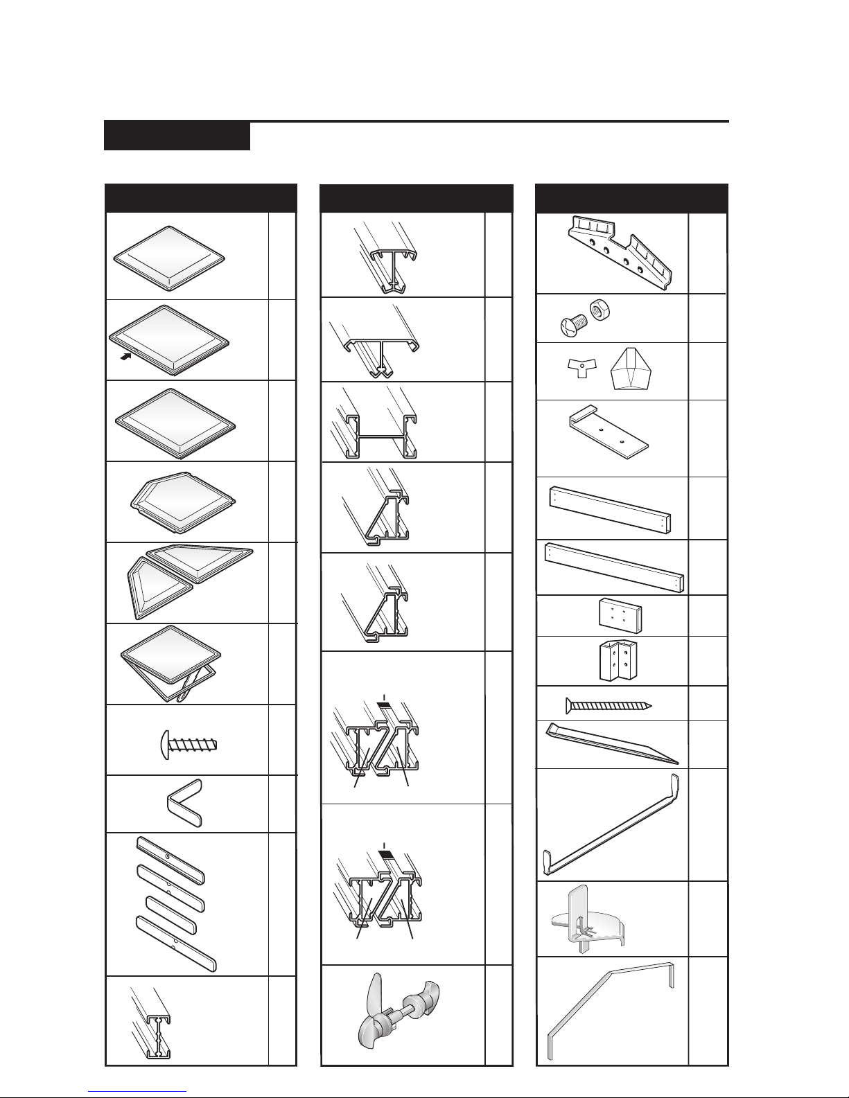
ITEM QTY.
CONTENTS
ITEM QTY.
ITEM QTY.
27
1
2
15mm (0.59") 10
2
3
2
2
Door
handle hole
23
10
10
24
8
1
31
1
32
33
1
5
3
2
4
(Assembly
required; see
steps 24A-C)
600 x 600mm
(23.6" x 23.6")
600 x700 mm
(23.6" x 27.5")
600 x700 mm
(23.6" x 27.5")
13
10
120mm (4.72")
100mm (3.93")
75mm (2.95")
120mm (4.72")
12
13
14
10
4
8
1
2
15
2
550mm (21.6")
17
1
6
6
21
22
10A
10B
10C
16
2
1290mm (50.7")
(Left door frame
and door jam)
(Bottom door jam
alignment bracket)
(Top door jam
alignment bracket)
(Door support)
1290mm (50.7")
550mm (21.6")
Door jam Door frame
(Door handle
assembly. Includes
3/32" allen wrench)
Plastic hinge plate
(Door frame
and door jam
assembly;
joined
together
with plastic
hinge plate)
(Door frame
and door jam
assembly
extension;
joined by
plastic
hinge plate)
(Left door frame
and door jam
extensions)
18
1
2
1190mm (46.8")
1290mm (50.7")
575mm (22.6")
530mm (20.8")
590mm (23.2")
1330mm (52.3")
Door jam Door frame
Plastic hinge plate
12mm (0.47")
11 18
8
590mm (23.2")
920mm (36.2")
1100mm (43.3")
1290mm (50.7")
4
2
19
1
25
26
27
28
29
16mm (.63")
4
4
40
6
4
6
30
797mm
(31.4")
920mm
(36.2")
Note: 1 inch = 25.4 millimeters (mm)
Important! Be sure to inventory and organize parts prior to beginning the assembly process.

1
Height:
200 cm (78.8")
1
6
1
1
6
1
1
1
1
5
4
1
3
1
3
2
1
1
5
3
3
3
1
3
1
1
Height:
10 cm (3.9")
Width:
193 cm (76")
25
Width:
190 cm (75")
26
25
1
26
25
1
Length:
247.4 cm (97.5")
26
26
25
25
25
Length:
245.5 cm (96.7")
3
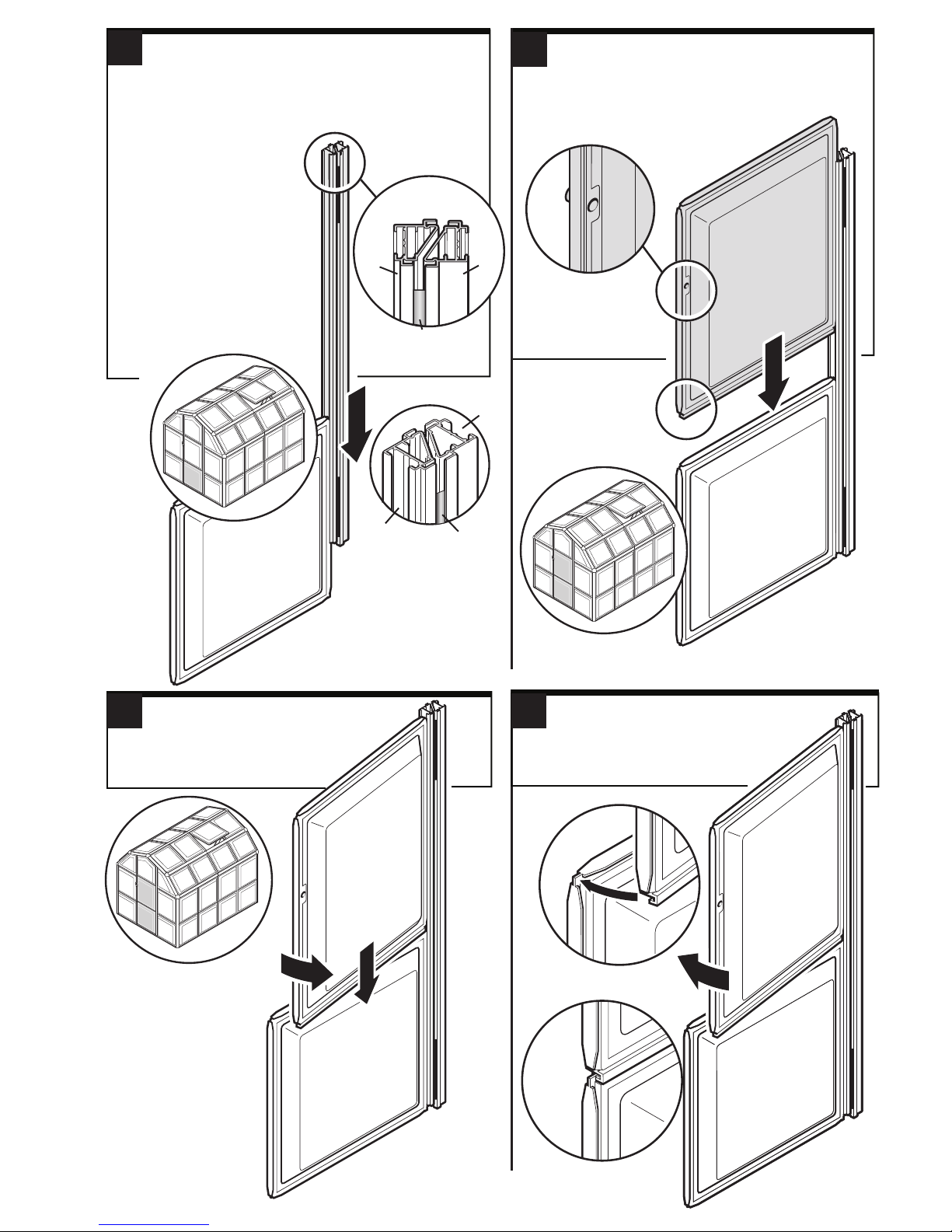
Door Assembly
1
Select profile 17-1290mm.
IMPORTANT: You must ensure that the profile is
oriented right-side up and with the plastic hinge
plates facing out (Fig A).
Slide profile onto a
square panel 1 (door
frame side
of profile).
Fig. A
(viewed from top)
Important: Note
orientation of angle
2
Slide the rectangular panel 2 (must be
the panel with the door handle hole) onto
the profile ensuring it has the interlocking
slot at its bottom.*
When necessary use a
lubricant to ease
connection between
aluminium profiles and
panels (mild soap and
water works well for this).
1
Door
frame
Plastic hinge
17/1290
Door
frame
Door
hinge
Door
jam
Door
jam
Door
handle
hole
Interlocking slot at
bottom of panel 2
MUST USE
PANEL
2
*
1
To interlock the two panels, first
3
pull the top panel back slightly
as shown (A), then push
down fully.
A
4
Push the top panel back so it
interlocks and is flush with
the bottom panel.
2
B
1
1
2
2
1
4
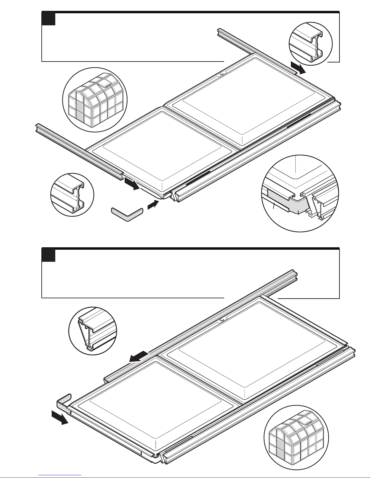
Lay the assembly on the floor and insert an angled bracket 9 only
5
into the bottom of profile 17-1290mm (A).
Slide a 11-590mm profile onto the top and bottom of
the door assembly (B), ensuring the angled bracket 9
slots into the bottom profile (see close up diagram).
1
11/590
11/590
B
2
B
9
11/590
Slide another angled bracket 9 into the other end of the bottom profile 11-590 (A). .
6
A
17/1290
Slide the 16-1290mm profile (B) on to the long side of the door
ensuring the angled bracket slots into the end of it .
IMPORTANT! Do nothing more to the door at this stage.
6
16/1290
B
11/590
2
9
9
A
11/590
1
5
 Loading...