

Page 1

Last updated: 08/13/20108 Rev. 9
1
R7 Build Instructions
1. INTRODUCTION
The R7 is so named as this was the revision the SMW3D/ Hobby-Fab team released; this DIY CNC router
kit. The kit is fully open source. In addition, the kit was released in beta and all feedback taken to
improve build and functionality. Thank you for joining us on this journey. We truly hope this build will
help makers to achieve the satisfaction of creating a machine that will provide years of creativity with
their own two hands.
2. SET-UP
We would love for you to rip open this package like it’s Christmas morning and you are eight years old
again. We must warn though, we have individually bagged the steps and they will match the below
inventory as well as the videos on YouTube on the SMW3D/Hobby-Fab page. The videos are labeled
R7v1, this means R7 video one, etc. Please DO NOT open every bag and dump the build on the table.
This will severely impact your build time and locating the proper parts for the steps. The build videos are
very outdated, they should only be used for reference.
We also advise finding a large, clean, flat surface to build your kit. The first few steps can certainly be
performed on a smaller surface however, as the build grows, you will need a four foot by four-foot area
flat surface. It is also advised that you lay out each step individually with all parts for the respective step.
Lastly, before starting the build, please note the BOM (Bill of Materials) is described below and two
columns are present after the item description. Please open each bag prior to build and count each item
and check it off the below list. If anything is missing, please contact us at contact@Hobby-Fab.com.
Performing this task now will prevent having to put off your build in the event we missed something.
Finally, please have fun and take your time. The build process will control all your cuts after, build it
once and build it right. The machine will provide years of great service.
Tools Required: (all should be locally available) Additional Items Required
Metric allen wrench set Bucket for water
Soldering iron and solder Table
Metric tap set Computer
8mm combination wrench USB A to B cable
10mm combination wrench Square and level
Page 2

Last updated: 08/13/20108 Rev. 9
2
Hand file
3. Build and BOM
The steps shown here will correspond with the SMW3D build videos. It should be noted these videos are
quickly getting outdated due to amazing feedback from users.
NOTE: as of November 2017, the mini wheels running inside the beam may be changed to Delrin.
NOTE: as of November 2017, mechanical limits are included in all R7 kits. The limits get installed as such:
Y gantry plate – limit faces rear of machine
X gantry plate – limit faces the right-hand side of the build looking at the machine
Z gantry plate – limit faces down
All wired NO
Step One:
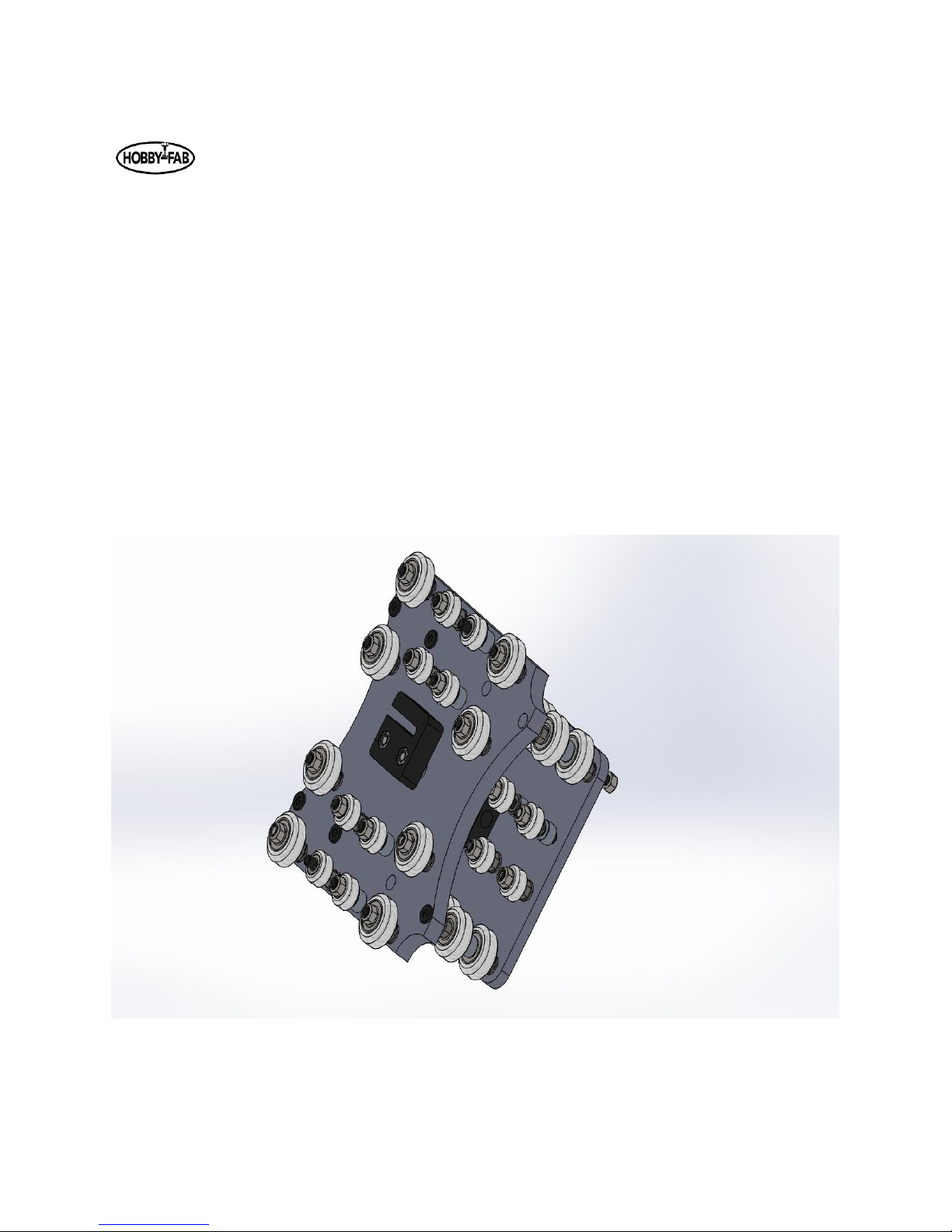
In the first step, you will be assembling the Y gantry plates. These plates will run on the side of the R7 as
you are facing the machine. One notable change from the videos is the .2mm shims are no longer
needed. At the end of this step you will have two assembled Y gantry plates, each with eight mini wheels
and three large wheels (all on M5 x25 bolts), the ACME block will also be installed (M5 x 20 bolts). Take
your time on the wheels. If all wheels touch the C-Beam, you are in a great spot. We state in the video a
tension is required. We have found this is not true. Each plate can take up to an hour and a half to
completely assemble. So, sit back, relax, and let's build.
Page 3

Last updated: 08/13/20108 Rev. 9
3
STEP 1
Qty.
Smw3D
Builder
Y Gantry Plate LH
1
Y Gantry Plate RH
1
Large Xtreme Wheels
6
Mini Delrin Wheels
16
Adjustable Tension Anti-Backlash Nut
2
6mm Spacers
8
6mm Mini Eccentric Spacers
14
3mm Spacers
4
M5x20 Bolt
4
M5x25 Bolt
22
Page 4
Last updated: 08/13/20108 Rev. 9
4
Note, the large wheels get a shim from the wheel bag between the bearings but not between the
eccentric spacer and bearing. The mini wheels get a shim from the wheel kit, between the bearings in
the wheel and between the bearing and eccentric spacer. All bolts are M5x25mm bolts. Note, you will
most likely need to remove the limit switch to install the one wheel bolt that resides behind it.
Begin by installing the standard spacers on the smaller holes (bottom row), these will be a reference for
the rest of the wheels. Tighten these with a small amount of torque, do not tighten so much that the
wheel drags or locks. Next, install the next row up eccentric spacers and mini-wheels. Before tightening,
turn the eccentrics until the wheel on this bolt is as close to the reference wheel below it. Install and
correctly tension the inner mini-wheels on the inside of the C-Beam (250 length), before installing the
outer larger wheels. Install the large wheels on the eccentrics and adjust to the beam in the same
fashion.
Page 5
Last updated: 08/13/20108 Rev. 9
5
The ACME block is installed by using two M5 x 20mm bolts, 3mm spacers, and two M5 nuts. Do not
over-tighten these M5 x 20 bolts, it is possible to collapse the block. Simply snug up and use lock-tight.
You can adjust the tension on the ACME block at this time if you so choose. Insert one of the ACME
threaded rods into the block and adjust the set screw until there is slight resistance while trying to turn
the ACME rod through the block. Do not overdo it. You can always adjust this after the build is complete.
Page 6

Last updated: 08/13/20108 Rev. 9
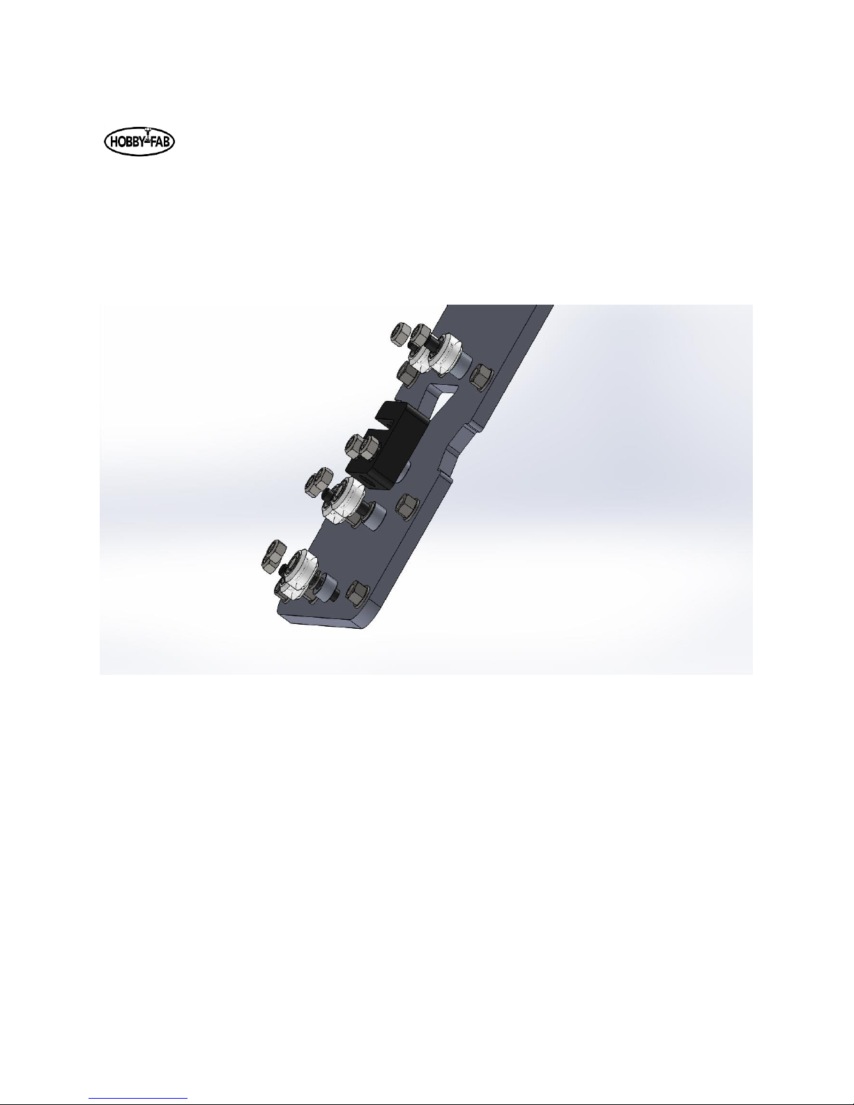
6
Limit switch and barrier block shown installed.
Page 7

Last updated: 08/13/20108 Rev. 9
7
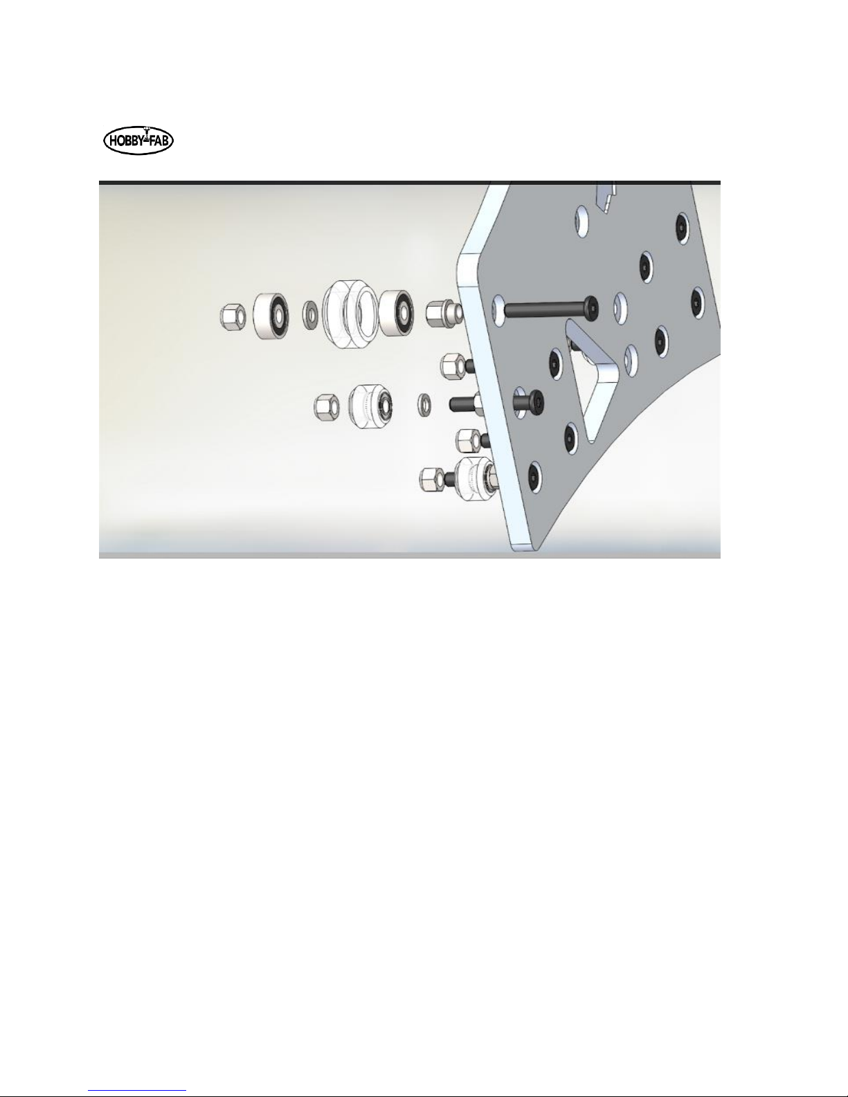
Step 2:
Step two has us assembling the front X/Z gantry plate. While looking at the completed machine, this will
be the front plate that holds the Z gantry and moves side to side in the X direction. Recall front to back is
Y and up and down is Z.
Note a change from the video, the Z is now driven by a single adjustable tension acme nut. Set the
tension on the ACME as we did in step one. Insert the acme rod and turn in on the set screw until there
is a slight resistance to turning the rod by hand. Do not lock the ACME in place by adjusting too far.
STEP 2
Qty.
Smw3D
Builder
Front XZ Gantry Plate (Machined)
1
Large Xtreme Wheels
8
Mini Delrin Wheels
8
Adjustable Tension Anti-Backlash Nut
1
1/4" Spacers
4
1/4" Mini Eccentric spacers
12
3mm Spacers
2
M5x20
2
M5x25
16
Note that all wheels are installed with ¼” eccentric spacers in this step to allow adequate room for the Z
gantry.
To begin assembly, note that one side of the plate has recesses. We will be installing bolts from this side
and the eccentric and regular spacers on the other side. Also, you will note one side of the inner gantry
wheel holes is smaller in diameter, we call these the reference holes. Install these and tighten down the
wheels, then use the eccentrics to add tension to the opposite wheels. All wheels on the reference holes
should touch the beam, this ensures a true Z. Install and correctly tension the inner mini-wheels on the
inside of the C-Beam (250 length), before installing the outer larger wheels. Install the eccentrics so that
the wheels are as close as possible to the reference wheels. Install the beam and turn the eccentric until
the wheel touches. Start in the center and work toward the top and bottom wheels.
Page 8
Last updated: 08/13/20108 Rev. 9
8
Install the outer wheels and turn the eccentrics until the outer wheels touch the C-beam.
The ACME block is installed in the same fashion as the first step.
Page 9
Last updated: 08/13/20108 Rev. 9
9
Note limit switch on bottom of plate, these wires will remain loose till install.
Page 10
Last updated: 08/13/20108 Rev. 9
10
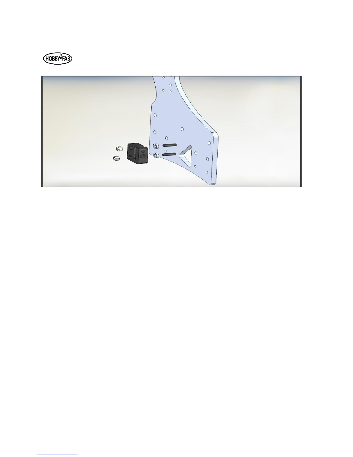
Step 3:
Step three will be the assembly of the rear X gantry plate. The same principles apply here. Use the
reference wheels as a base and adjust the eccentrics to touch the inside of the sample beam (250mm
length Z). Continue by installing the ACME block with the supplied 3mm spacers and M5 x 20mm bolts.
Again, it is a good idea to adjust the tension on the ACME block at this time.
Note this plate is completely remodeled but the assembly remains the same.
Page 11

Last updated: 08/13/20108 Rev. 9
11
Notch in plate faces down. Limit switch on the left-hand side looking at the plate.
Page 12

Last updated: 08/13/20108 Rev. 9
12
STEP 3
Qty.
Smw3D
Builder
Rear XZ Gantry Plate
1
Adjustable Tension Anti-Backlash Nut
1
Mini Delrin Wheels
8
3mm spacers
2
m5x20
2
m5x25
8
6mm Spacers
4
6mm mini eccentric spacers
4
Page 13
Last updated: 08/13/20108 Rev. 9
13
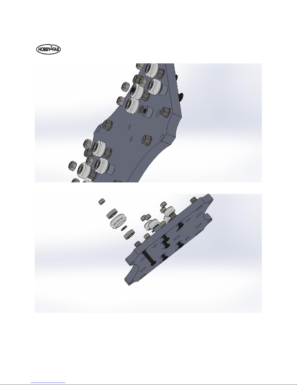
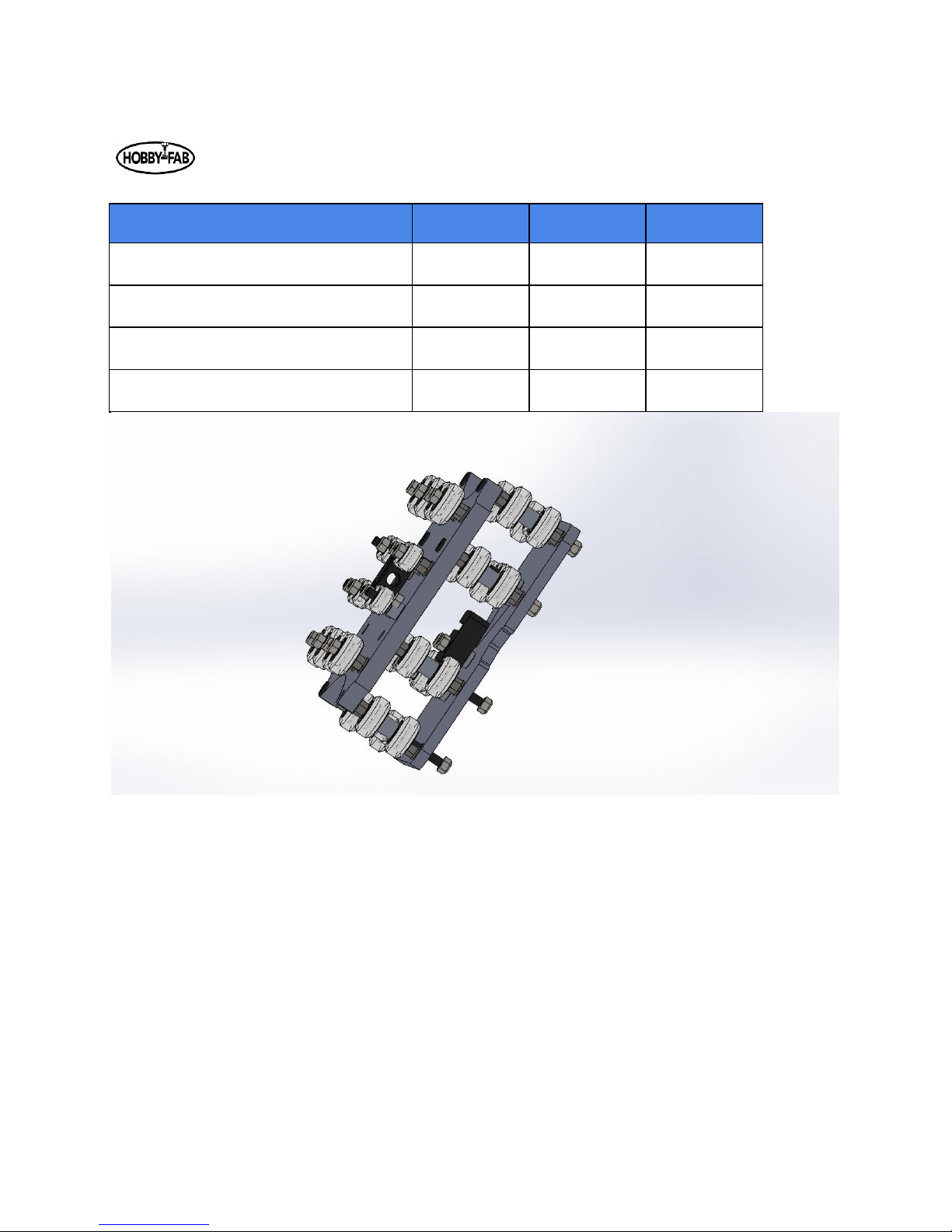
Step 4:
Step four will be the joining of the front to the rear X gantry plates. When you have all the large wheels
in place, apply a light amount of tension on the M5 nuts to hold everything together. Then, adjust the
eccentrics so that the wheels are as far away from the center of the X axis as possible.
Once the wheels are installed and eccentrics have them spaced out, slide your 250mm length C-beam in
and adjust the tension evenly. Turn ⅛ of a revolution on the two eccentrics on one axle at a time. Start
with the far-left top corner then go to the top right corner, then the right bottom, then the left bottom.
If all are touching, you’re done. If not, repeat by turning each axle eccentrics ⅛ of a rev again. Once the
outside wheels all touch, move to the inner wheels.
There are no shims used here except for those between the bearings on the wheel kit. The assembly is
plate, eccentric, wheel, 9mm spacer, wheel, eccentric, plate.
Page 14
Last updated: 08/13/20108 Rev. 9
14
STEP 4
Qty.
Smw3d
Builder
Large Xtreme Wheels
16
9mm Spacers
8
6mm Mini Eccentric Spacers
16
M5x60
8
Page 15

Last updated: 08/13/20108 Rev. 9
15
Step 5:
Step five we will mount the spindle to the Z gantry. The Z gantry will be the up and down axis of the
machine. Note, the spindle clamp has been modified from the video. These spindle clamps are very
fragile in the un-mounted state. Be cautious with these. Do not try to bend them or force them open
with excessive force. Simply slide the clamp on the end of the C-Beam, install with a T-nut and M5 x 8
screw on both sides, and tighten. The clamp will be tight when installing the spindle. You can gently
spread the clamp by hand and slide in the spindle. The clamps should be on the stainless caps of the
spindle.
STEP 5
Qty.
Smw3d
Builder
800w Spindle
1
Spindle Clamps
2
M5 T-Nuts
4
M5x8
4
M5x35
2
250mm C-Beam
1
Page 16

Last updated: 08/13/20108 Rev. 9
16
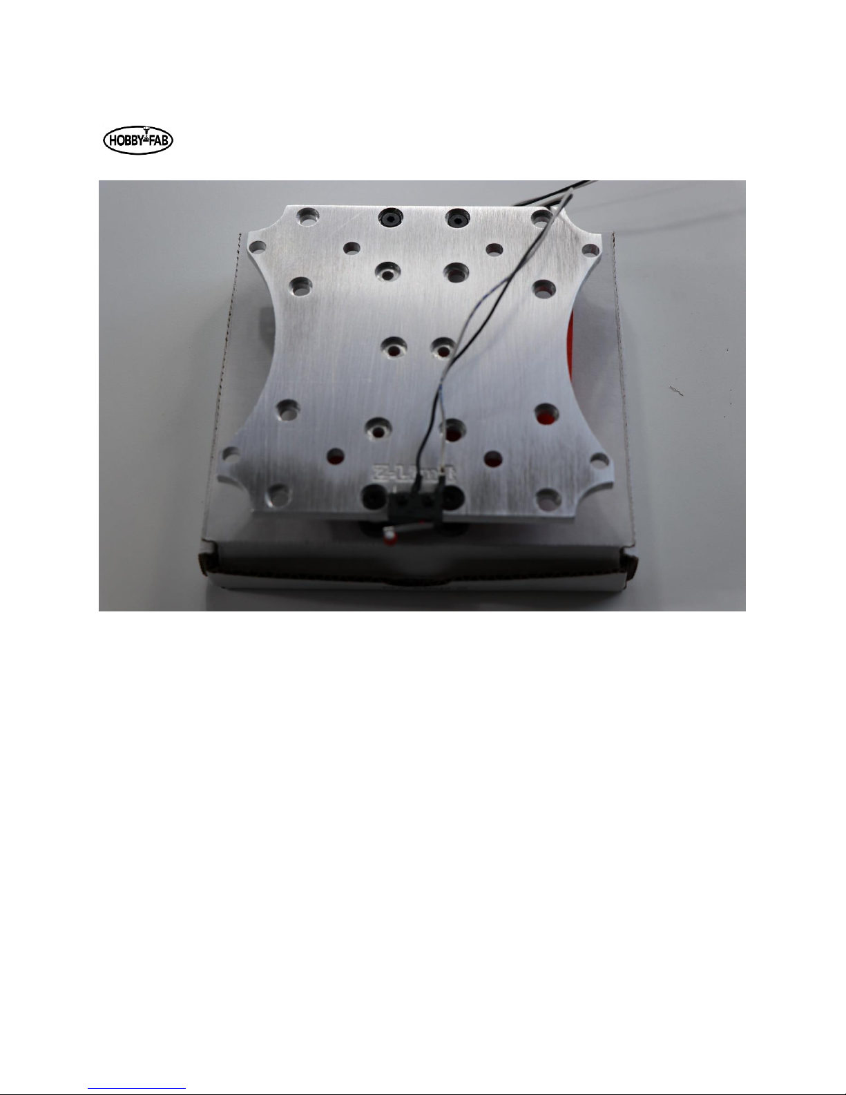
Note, you can see both limit switches from the back view.
The Z-limit wires can now be moved directly up (in relation to the picture) and through the notch in the
rear plate and inserted into the Z-Axis screw terminals.
Page 17

Last updated: 08/13/20108 Rev. 9
17
Step 6:
Step six we will build the X gantry. Note, on the X gantry there will be a piece of 1000mm length C-Beam
and a 1000mm length 20x20 V-Slot. The V-slot will be the exact same length as one piece of C-Beam.
The ends of the beam will be colored to indicate the matching C-Beam and 20x20 aluminum V-slot.
Please lay all out and find the piece of C-Beam that matches the 20 x20 x1000mm perfectly.
We will be mounting these two beams between the left and right Y gantry plates. We will also be
mounting the first stepper motor to drive the X axis. The motor can be mounted on the left or right Y
gantry plate. One should think about the final installation of the machine at this time and debate if there
will be an advantage to the motor being mounted on one side or the other for space reasons. The
M5x15mm bolts will hold the beams to the Y gantry plates. The bearings will fit into the recesses in the
outside of the Y gantry plates. The ACME will thread through the anti-backlash nut on the X gantry we
built in a previous step.
Prior to installation, it is advised to lightly sand down the ends of the ACME to allow the 608ZZ bearings
to slide over the ends of the ACME. Only about .2mm need be removed from the OD of the final 40mm
of both ends of the ACME. The bearings and ACME will be held in place by the 8mm lock collar on the
end opposite of the motor, and the coupling on the motor side.
Install the X gantry on the C-Beam, thread the ACME through block on the X gantry, then install the two
side plates with the provided M5x15mm bolts.
Page 18

Last updated: 08/13/20108 Rev. 9
18
STEP 6
Qty.
Smw3d
Builder
M5x15
10
M5x55
2
1.5in spacers
2
608ZZ Bearing
2
8mm lock collar
1
6.35x8 Coupler
1
1000mm Acme
1
1000mm 20x20
1
1000mm C Beam
1
NEMA 23 2.8A
1
Shim: 12.5x8x1.5
2
Page 19

Last updated: 08/13/20108 Rev. 9
19
Page 20

Last updated: 08/13/20108 Rev. 9
20
Above, the motor installation is shown. Use the two longer bolts and spacers to attach the motor. Install
the bearing, washer, and coupler as shown. Tighten all set screws on the coupler once the ACME is fully
engaged.
Page 21

Last updated: 08/13/20108 Rev. 9
21
The opposite side is constrained by the lock collar. In the step seven bag you will find an ACME nut plate.
Use this to push the lock collar flush against the bearing and remove any slack from the drive. Excessive
force is not needed. Simply tighten down the nut plate while holding the coupler on the other end, then
tighten the set screw. Remove the nut plate afterward.
Page 22

Last updated: 08/13/20108 Rev. 9
22
Step 7:
Step seven will be the build of the Y gantries. Your machine is really going to take shape after this step.
This step is much of a repeat of the last, but we will be mounting end caps instead of Y gantry plates.
Step 7
Qty
Smw3d
Builder
NEMA 23 2.8A
2
6.35x8 Coupler
2
Machined end corner caps
4
Lock collar
2
608ZZ
4
C-Beam 1000mm
2
1.5" spacers
4
M5x55mm bolts
4
M5x20mm bolts
20
Single corner bracket
4
M5 nuts
4
1000mm ACME
2
ACME flange nut
1
Shim: 8mm
4
Each corner bracket holds the ACME in place and retains the build to the board.
Page 23

Last updated: 08/13/20108 Rev. 9
23
Front machined end caps shown above.
The L-shape should face the inside of the C of the beam.
Rear machined plates have been modified, installation is the same but now has wiring blocks.
Page 24

Last updated: 08/13/20108 Rev. 9
24
It is best to install the wood screws into the spoiler board near the last step when we can square the
build. If you choose to install them now, thread the ACME in until the Y gantry plates are the same
distance from the corner plates. Then, install the corner plates square with the front edge of the spoiler
board.
Y rear machined end plates
Page 25

Last updated: 08/13/20108 Rev. 9
25
Step 8: We will assemble the full Z gantry in this step. Grab the Z gantry with the spindle and prepare to
install this with the 250mm ACME. This axis is in compression versus the previous tension set-ups.
Step 8
Qty
Smw3d
Builder
C-beam end plates
2
M5x55mm
2
1.5" spacers
2
250mm ACME
1
688zz
2
6.35mm x 8mm coupler
1
Nema 23
1
M5x25mm
8
8mm Lock Collar
2
Shim:12.5x8x1.5
2
Page 26

Last updated: 08/13/20108 Rev. 9
26
Thread the ACME through the anti-backlash nut, then slide the lock collar, bearing, and shim over the
top. Attach one of the black plates on the top of the Z via the supplied M5 x 25mm bolts. Feed the Z
gantry down through the wheels in the front of the X axis. Continue to slide down until there is enough
ACME hanging out of the top of the plate to fully engage the coupling. Set this height by tightening the
lock collar on the ACME and trap the shim and bearing into the recess on the plate. Attach the motor as
in the previous step. On the lower portion, perform the same task. Slide a lock collar, bearing, and shim,
then the plate over the bottom of the ACME. Lock the axis in place by tightening the set screw on the
lower lock collar.
Watch the play in the Z final assembly. You should not be able to wiggle the spindle up and down.
Sometimes it is easier to leave a slight gap between the C-Beam and the end plate, then slide the lock
collar all the way down, lock in place, then tighten the 4 qty. M5x25mm bolts. Do not overly compress
the ACME. A very small gap of about .01mm is all that is needed when tightening the axis to remove
play.
Page 27

Last updated: 08/13/20108 Rev. 9
27
Page 28

Last updated: 08/13/20108 Rev. 9
28
Page 29

Last updated: 08/13/20108 Rev. 9
29
Step 9: Let us add some peripherals.
Step 9
Qty
Smw3d
Builder
3/16" ID 5/16" OD vinyl tubing
30
4 pole wire 18 to 22g
36
3 pole wire (typically 16g)
18
15mmx30mm cable chain
2
M5 drop-in T-nut
1
M5 x 10mm bolt
1
9mm spacer
2
Water pump
1
M5x20mm bolt
1
Sheathing 10mm
10
M5 x 25mm bolt
1
Figure out where you want your electronics and water reservoir. It is highly advised they are not in the
same location.
Run the cable chain down either the left or right side of the build. Mount one end to the y gantry plate.
One plate will have a threaded hole in the middle of the hobby-fab logo, this is for the Y cable chain.
Reduce the Y cable chain to half the shipped length. You will need to remove one end of the cable chain.
If you remove the proper end, you will be left with a hole in the side of the cable chain where the mount
end was “tabbed” in. Use this hole, a 9mm spacer, and M5x20mm bolt. Mount this end upside down
and cable chain extending facing the front. Mount the other end right side up with a wood screw to the
spoiler board, again aimed towards the front.
Page 30

Last updated: 08/13/20108 Rev. 9
30
Page 31

Last updated: 08/13/20108 Rev. 9
31
Mount the X cable chain in the same method. Attach the upside-down end to the back of the Z gantry.
There is a threaded hole in the upper corner of the rear plate. Use two 9mm spacers and the M5 x
25mm bolt, attach the other end to the top of the 20x20x1000mm v-slot with the drop-in tee-nut and
M5x10mm bolt.
At this time, it is best to remove the cable chain tops, as we will route wires and cooling hoses through
both.
Install the water tubing by taking the nuts off the top of the spindle. Install a hose and route through
both cable chains to exit at the rear of the machine. Route a hose to your tank and attach to the top of
water pump. Route another hose to the tank and allow to flow into the tank. The video R7v9 provides a
good example of a tank you can use. If your tank is a good distance away, you can pick more tubing up at
most home improvement stores it is 3/16 ID by 5/16 “ OD.
Install the three wires from the spindle to the terminal block on the back of the rear X gantry plate.
Page 32

Last updated: 08/13/20108 Rev. 9
32
Page 33

Last updated: 08/13/20108 Rev. 9
33
Step 10:
You have made it! The final step is the electronics of the kit. This video is rather short, so when you have
questions hit the G+ group up and the team of builders will be happy to assist!
The video is meant for builder that purchase the all in one control box. See the end of this document for
detailed instructions.
Communicating with the machine:
If you have the all in one PRO control box communication is held internal to the machine. Use the video
and instructions at the end of this document.
If you have the all in one simple control box, you will need a computer and follow these directions.
Plug a USB cable A to B into the control box.
Start your computer and open a google chrome window.
Go to this address:
https://cnc.js.org/docs/desktop-app/
Download the appropriate desktop app for your system, OS, windows, etc.
Open CNC.js
Look for a connection window on the top left hand side.
Power the machine.
Under port, hit the refresh button, use the drop down to find the USB port.
A blue button labeled “Open” is also in the connection window. Click this button.
You should now be connected. You must home the machine prior to jogging around. There is a blue button
labelled “Homing” in the upper right-hand corner, click this.
The machine should raise the Z, then lower a bit, then go back up. X and Y axis should follow.
Once homing is complete you can now jog around.
If you jog the wrong direction, you will lock grbl. The system purposely does this to avoid damage. If
locked, simply hit the refresh and unlock buttons located near the homing button.
You are now connected to the machine and it is fully usable!
You can try jogging around, homing the machine, starting the spindle (M3 S1000), etc.
Page 34

Last updated: 08/13/20108 Rev. 9
34
Take time to familiarize yourself with this window. There are a lot of features here. If you want to jog the
machine around go to the upper right-hand window, called Axes, click the down button and the box will
expand. Click on the “move” tab and select “1”
Then click any of the direction buttons. The machine should move.
GRBL Settings change:
Example
If an axis such as X, Y, or Z moves in the opposite direction it should you will need to change the “$3”
mapping. For an understanding of this see the GRBL page:
https://github.com/grbl/grbl/wiki/Configuring-Grbl-v0.9
Scroll down a bit and you will see a set of numbers “$1” through “$132”, below this is an explanation of
what each does. Related to the example above, if X moves the opposite direction we tell it, we would
need to set “$3=1” based on this information:
Setting Value
Mask
Invert X
Invert Y
Invert Z
0
00000000
N N N
1
00000001
Y N N
2
00000010
N Y N
3
00000011
Y Y N
4
00000100
N N Y
5
00000101
Y N Y
6
00000110
N Y Y
7
00000111
Y Y Y
To make changes, go to the Com screen. Look in the mid-left-hand side of the screen. Note it is black with
white text.
At the bottom of this box you will see an area where you can type things, type in this box, $$
You will see what your current settings are. Only if an axis is going the wrong direction should you make
the below change.
Page 35

Last updated: 08/13/20108 Rev. 9
35
Note that $3=0 out of the list of things there.
Type $3=1
Then type $$
Note that now in your list $3=1, and when you jog the machine X now moves in the opposite direction. If
all axis move in the wrong direction you would type $3=7, for example.
One last thing to check is that the spindle turns the right direction. Type M3 S12000 in the serial port.
This should turn the spindle on at 12000 RPM. Type M5, the spindle stops. Looking down at the top of
the spindle, it should turn to the right.
The machine is set up and ready to be used! Play around with the $ settings. Set travel limits, set max
velocities and accelerations.
Have a read on our page about “How to CNC” here: https://www.smw3d.com/blog/how-to-cnc/
Read about feeds and speeds here: https://www.smw3d.com/blog/what-is-the-right-feeds-and-speeds-
for-my-cnc-router-kit/
Explore the machine, explore software, explore all that various things you can create. There is so much
to learn and new opportunities around every corner when you can build the world around you.
Join us and show off your build on the R7 Google Plus page. We look forward to the amazing things you
will build!
Page 36

Last updated: 08/13/20108 Rev. 9
36
Laser install instructions
2.8w laser add on is identical for OX and R7.
If opted for during purchase a J-tech 2.8w complete laser system will be added to the order.
Safety:
Please open this package and carefully read and understand the safety warnings associated with this
product included in the package.
Lasers are dangerous, fire hazards and eye safety should always be the end user’s top priority when
using the laser add on feature.
Never leave the laser unattended when in operation!
Always wear the safety glasses provided in the kit when using the laser diode add on. If more than
one party is in the local vicinity they should also have the required eye protection.
It is suggested to keep fire suppression equipment close at hand and prepared for an emergency.
SMW3D, Hobby-Fab, J-Tech and affiliated groups hold no liability to property, personal, or any other
damage created from the use of this product. The purchase and use of this laser add on system is
strictly the end user’s liability and responsibility to ensure safe use.
Specifications:
Please see the J-tech instruction manual for full details.
https://jtechphotonics.com/wp-content/uploads/2013/05/Instruction-Manual-445nm-Laser-DiodeComponent-9mm-G2-Lens-J-Tech-Photonics-Inc.-v2.pdf
Bill of Materials:
• 2.8w J-tech laser system with extended wires
• Modified spindle clamps
• 2 quantity M3 x 12mm bolts
Installation:
The spindle clamps in your kit will have 2 additional holes tapped into the side of one of the spindle
clamps. There will be two bolts pre-installed in the spindle clamp.
This clamp will be the lower clamp on the spindle closer to the collet side of the spindle.
Page 37

Last updated: 08/13/20108 Rev. 9
37
Shown above on the 400-watt spindle, 600w and 800w are identical.
These holes should center the laser in the Y plane with the spindle center.
Open the laser package and look for a small bracket that will fix a fan to the back of the diode laser.
Page 38

Last updated: 08/13/20108 Rev. 9
38
Install the laser diode with this bracket. The laser should face downwards with the fan mounted on the
bracket with the Sunon logo facing the diode. It is advised to install the laser M3 bolts with blue thread
lock.
The laser diode and fan wire should be routed through both the X and Y cable chain and exit near the
control box area.
Page 39

Last updated: 08/13/20108 Rev. 9
39
The laser diode will connect to the driver board on the H3 header and the fan will connect to the fan
header.
Page 40

Last updated: 08/13/20108 Rev. 9
40
1 Shown uninstalled for relation
Next connection will be the PWM signal. Regardless of the GRBL controller sent we will utilize the PWM
+ and – signals to control the laser power.
Page 41

Last updated: 08/13/20108 Rev. 9
41
Connect the bare ended wire with the molex connector on the opposite side next to the laser connector,
connect the other end to the PWM positive and negative connections on the board. Polarity matters. On
the all in one controller the accessory port, yellow is PWM +, blue is PWM -.
Connect the supplied power supply with the barrel connector to the laser driver board.
The laser add on is now ready for use.
Page 42

Last updated: 08/13/20108 Rev. 9
42
Use:
When the laser driver board is powered for the first time, every use, the reset button must be pressed.
Insert the safety key, turn on the power and press the rest button. The fans should both come on along
with a green LED indicating the driver board is ready for use.
Vector Gcode can be created in the same fashion as we create routing Gcode. A spindle speed of 4000
(lowest setting on most our products) will be the minimum power. A spindle speed of 12000 will be
maximum power.
Raster jobs are best created by other software than the ones we use for routing gcode generation. They
provide more efficient code.
Once gcode has been created, load gcode into your communication software, such as CNC.js or bCNC.
Locate the serial port box, in CNC.js this is the black box in the middle of the left-hand side of the screen.
bCNC this is the upper right-hand corner of the screen, a tab called terminal.
Type $$ and hit enter.
Note that $32=0 currently. Router control is standard in this mode. Type $32=1 and hit enter. The
machine is now in laser mode.
Making this setting change turns off the spindle power, hence the laser power during G0 moves and
enables during G1, G2, G3 moves.
As an example, in code G0 X1 Y1 Z1 the laser will be off moving or rapid to this location. The next move
F600 G1 X2 Y2 Z2 will turn on the laser and move to this location. The next rapid of G0 will turn off the
laser.
The power of GRBL allows the use of standard routing gcode to be used in this method without the need
for special commands to operate the laser.
Page 43

Last updated: 08/13/20108 Rev. 9
43
Focus Length and Gcode generation:
The J-Tech diode has a focus length of around 3” from the factory. When setting the work piece home
use a tape measure or calipers to ensure the diode is this distance away from the work piece. Set this as
your Z=0.
When producing gcode for laser use, use a very small Z depth of cut (DoC) such as .001 units. Also,
clearance height can be reduced to 0 for maximum efficiency.
The number one mistake we make here is forgetting to turn the machine back to router mode. After
laser operations recall to set $32=0.
Any questions please do not hesitate to contact us we will happy to assist.
Contact@hobby-fab.com
Page 44

Last updated: 08/13/20108 Rev. 9
44
Please read this entire document before installing and using the all in one control box.
WARNINGS:
Do not connect the 110VAC power cable till all motors are connected.
Do not disconnect any stepper motors while the control box is powered.
Mount the box to something non-conductive. A ground loop can be created between the box and
machine if connectivity is allowed other than intended connections.
Do not place any electronics on top of the control box including 600w PSU/ESC, etc. The noise will
cause erratic behavior.
Do not open the control box, wires can be dislodged.
If the shipping box is severely damaged upon receipt please DO NOT PLUG THE BOX INTO A WALL
OUTLET. The box is internally grounded and fused for both AC and DC but your safety is top priority, a
damaged box should not be used. SMW3D, Hobby-Fab and related affiliates hold no responsibility for
damage to equipment or persons by using this product. Be safe, be smart, build!
CARE:
The control box is made of cold rolled steel and the early units have a black oxide coating. This is a
similar process to bluing a firearm. In the same sense the outer surface of the box can be protected in
the same manner. Using any type of firearm protectant or light oil will protect the box from rusting.
Avoid spraying the box with an aerosol, instead spray a rag and wipe the box down.
Hobby-Fab Controller
Page 45

Last updated: 08/13/20108 Rev. 9
45
Connections:
Step 1:
Connect all stepper motors to the X, Y, (if using a gantry style machine Y2) and Z. The 6 pin connectors
are labelled below. Looking at the face of the box the connections are, from left to right:
Accessories :
Black/ White = Z probe Yellow/Blue = (+/-) PWM Red/Green = (+/-) 010V
X Axis:
Black/White = X axis limit switch Yellow/Blue = 1A 1B stepper motor pair Red/Green 2A/2B
Y Axis:
Black/White = Y axis limit switch Yellow/Blue = 1A 1B stepper motor pair Red/Green 2A/2B
YNL: (this is only needed on gantry style machines with two Y motors)
YNL stands for Y axis no limit, the black and white wires are not present on this axis.
Yellow/Blue = 1A 1B stepper motor pair Red/Green 2A/2B
Z Axis:
Black/White = Z axis limit switch Yellow/Blue = 1A 1B stepper motor pair Red/Green 2A/2B
NOTE: If your machine is a kit from us this will directly plug (color to color) into the steppe r motors and limit
switches.
NOTE: All limit switches are filtered and should be used in the NO (Normally Open) position.
Page 46

Last updated: 08/13/20108 Rev. 9
46
Step 2:
Make sure the E-Stop is “out” this allows power to the control board.
Step 3:
Plug in a USB style Mouse and Keyboard to either USB port on the front.
Step 4:
Plug an HDMI monitor into the port on the face.
Step 5:
Plug the 110VAC cable into the fused connection on the far left.
Step 6:
Turn on the master switch.
ACC X Y YNL
Page 47

Last updated: 08/13/20108 Rev. 9
47
USE:
Every control box is tested prior to shipment. Based on your machine some changes may be required
prior to use.
E-stopping the box kills power to the motors, but does not remove power to the program. In the event
of an issue, one should be able to retain the current program and restart after homing.
There are two 110VAC outlets on the front of the box, next to the AC power in. The upper plug is a fused
direct 110VAC plug, do not plug anything over 5A into this outlet. The lower plug is controlled by M8
commands. Typing M8 in a program will deliver 110VAC to this plug, typing M9 will remove power to
this plug.
Settings may need to be modified prior to use. When plugged in the monitor will display a logo while
boot up is taking place. Once this splash screen is complete the system will open to bCNC and connect
automatically.
THE MACHINE MUST BE HOMED PRIOR TO JOGGING
There is a home button on the control tab at the upper left-hand corner. Click home.
You should expect the Z axis to go up, touch the limit switch, go down, then come back up. After this
action X and Y should both start moving towards the limit switches.
If the machine does not move in the correct direction. Click the unlock and reset button in the upper
left-hand corner of the file tab. This will stop all motion.
Go to the upper right-hand corner and find the terminal tab.
Click on this.
A serial port message box will be on the left-hand side of the screen with an area to type in at the
bottom.
Type $$
These are your GRBL Settings you will need to invert the Z if it went the opposite direction. This is done
by typing $3= (some number that corresponds below)
Page 48

Last updated: 08/13/20108 Rev. 9
48
Setting Value
Mask
Invert X
Invert Y
Invert Z
0
00000000
N N N
1
00000001
Y N N
2
00000010
N Y N
3
00000011
Y Y N
4
00000100
N N Y
5
00000101
Y N Y
6
00000110
N Y Y
7
00000111
Y Y Y
For instance, when you typed $$ and hit enter, and your current $3=1 and your Z was going the wrong
direction, try $3=6 hit enter.
Try homing the machine again. Continue the above till all 3 axis are homed.
Post the above exercise and homing you are ready to CNC.
Play around inside bCNC and read more at the links provided within this document.
Setting workpiece zero is as simple as jogging to the location and clicking the X=0, y=0, z=0 buttons on
the control tab below the digital readouts.
Page 49

Last updated: 08/13/20108 Rev. 9
49
Please email or call if there are any issues we are happy to assist.
contact@hobby-fab.com or 346-333-6500.
 Loading...