


Instruction Manual
Senior
Tele
m
aster
Plus AR
F
Wingspan:
Length:
Wing Area:
Weight (with battery):
94 in.
64 in.
1330 sq. in.
9 pounds
!
1

Before starting, use the
Contents list to take an
inventory and make sure it is
complete. If any parts are
missing or are not of
acceptable quality, contact
Hobby Express Support at
1-615-373-1444 .
This manual assumes the
builder possess intermediate
assembly skills. Seek help
from another pilot or an
experienced modeler if you
are unsure how to complete any steps in this manual.
Contents List
! Fuselage
! 2 Wing Panels
! 2 Horizontal Stabilizers
! Vertical Stabilizer and Rudder
! Aluminum Wing Joiner Tubes
! Aluminum Stab Joiner Tubes
! 2 Aluminum Wing Struts
! Wire Landing Gear
! Main Wheels and Steerable Tail Wheel
! Wooden Motor Mount
! Pushrods, Control Horns, Pin Hinges and assorted fasteners
Additional Items Required
! 6-channel Aircraft Radio w/ Receiver (minimum)
! 5000mah, 5-cell, 18.5v Lipo battery
! (6) Standard sized servos
! (4) 24” Servo extensions
! (2) 12” Servo extensions
! (3) 6” Servo extensions
! (1) Servo Y-harness
! 70-80 amp Brushless ESC
! AXI 4120/18 Brushless Motor and radial mount set
! APC 14x10 “E” Propeller
! Glues, solder, connectors
2
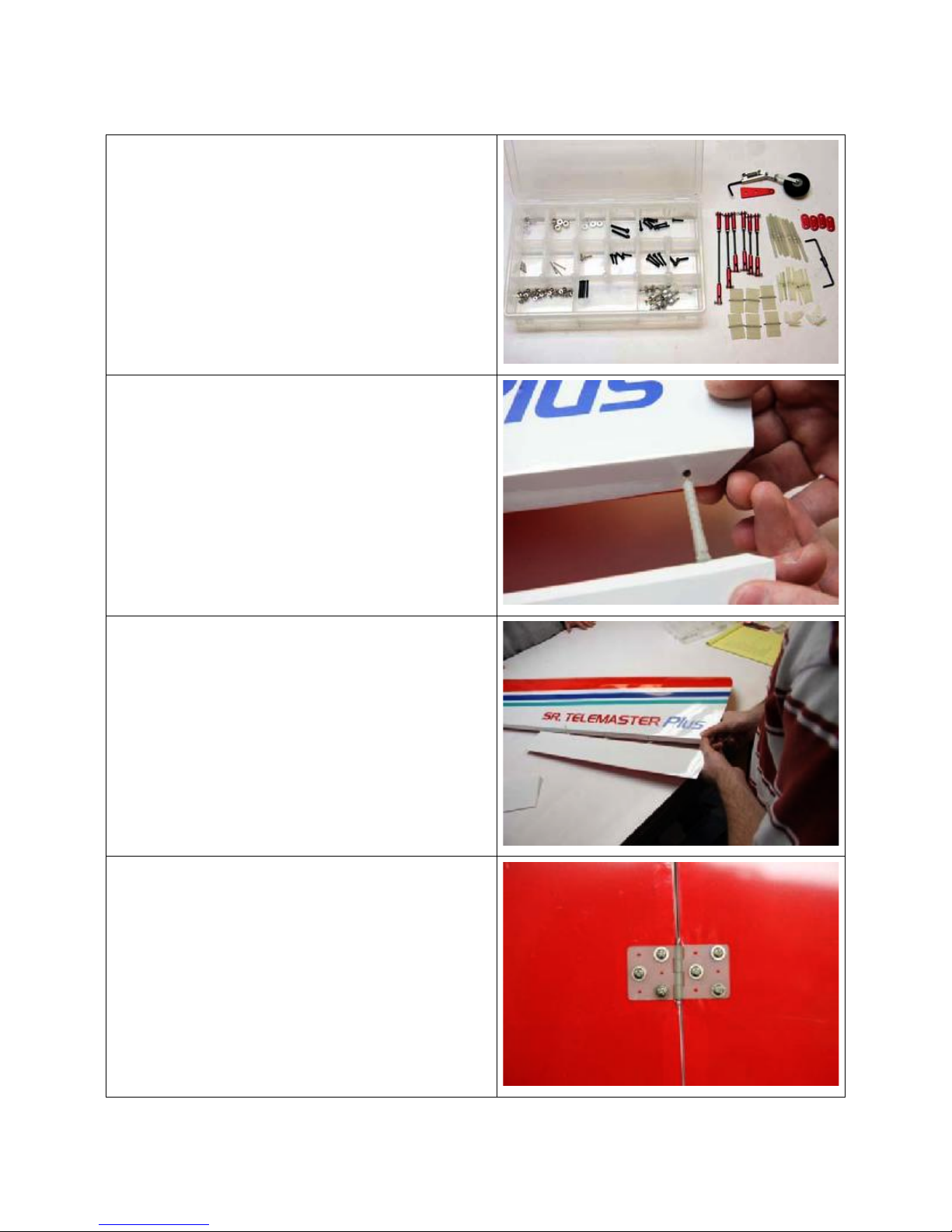
1. After unpacking all parts, sort the
hardware and place like parts into
separate holders. This will speed the
building process and give you a good
visual of all the hardware provided.
2. Begin by hinging the ailerons to the main
wing panels using the larger pin hinges.
Apply a drop of 3-in-1 oil to the pivot of
each hinge point; this is to keep the glue
from fouling the hinge operation. Use 30minute epoxy and insert into each hole
of the control surface, then insert the
hinge and set aside to cure.
3. Once the hinges are set in each control
surface, dry fit them to the wing panels
and check that the movement is smooth
and the alignment is suitable. When
satisfied, apply glue to the hinge
pinholes in the wing and insert the
control surface into position. Maintain
small gaps between the main wing and
the control surface. Check for free
movement.
4. Now find the 6 flat hinges and 18 of the
smallest screws. Locate the mount
points on the wing and flaps (there are
hardware blocks under the covering) and
use a screwdriver to install the flap
hinges.
3
5. After all wing control surfaces are hinged
and the epoxy has cured, check for free
movement and prepare to install the
servos.
6. Add a 12” servo ext. to the Flap servos
and insert the servos in the wing. Screw
in place with the output shaft facing the
trailing edge of the wing.
7. Locate the control horns and pushrods
and install them for both flaps.
8. Repeat the process to install the servos,
control horns and pushrods for the
ailerons. Use 24” extensions for the
aileron servos. The aileron servos are
oriented in the same direction as the
flaps with the output shaft facing the
trailing edge of the wing.
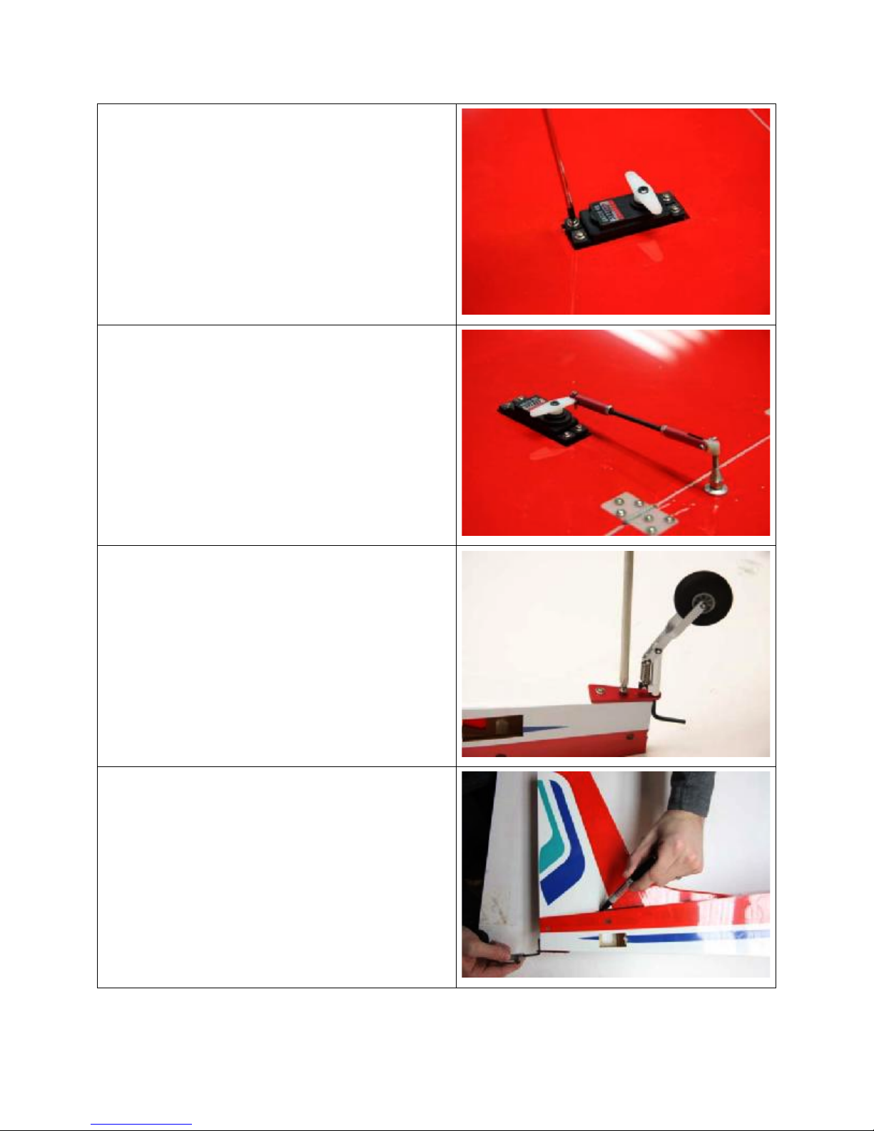
9. Locate the tail wheel, mounting plate,
and two screws. Install the tail wheel as
shown.
10.Dry fit the vertical stabilizer in the
fuselage. Use a marker and mark the
vertical stab where it meets the fuselage.
Use a hobby knife and remove the
covering below the marked line. Cut the
covering about 1/8” below the marked
line. Use only enough force to cut the
covering. Do not cut into the wood.
4

11.Tape off the area on the fuselage with
masking tape, mix up some 30-minute
epoxy and glue the vertical stab in place.
The stabilizer should be flush with the
back of the fuselage. Make sure it is
straight while the glue cures. Clean up
any epoxy that squeezes out with a paper
towel and rubbing alcohol.
12.Trail fit the rudder using 3 pin hinges.
Trim the covering away where the tail
wheel steering wire inserts in the rudder.
13.Epoxy the tail wheel wire and the 3 pin
hinges to the rudder and vertical fin in the
same way you did with the ailerons and
flaps. There should only be a small gap
between the fin and the rudder.
14.Once the epoxy has set, install the rudder
nylon control horn.
15.Connect a 24” servo extension to the
rudder servo and install the servo with
the output shaft facing forward as shown.
You can tape the servo lead to the
extension so they will not be accidentally
disconnected.
5

16.Locate the Horizontal Stabilizer, eight
smaller pin hinges, a nylon control horn,
pushrod, aluminum tubes, and the
elevator U-Connector.
17.The U-connector can be separated with a
setscrew. This allows you to remove the
horizontal stabs later for transport. The
larger connector piece needs to be glued
into the right elevator and the matching
wire glued into the left elevator as shown.
18.Now hinge the elevator control surfaces
to the stabilizers with 30-minute epoxy
making sure not to foul the hinge pivots
with glue. Check for free movement.
19.Insert the aluminum tubes in the fuselage
and slide on the horizontal stabilizers.
20.Make sure the U-connector pieces line up
and that the wire piece inserts into the
connector. Move the rudder over to
access the setscrew and tighten it with an
Allen wrench. Make sure the elevators
are aligned before tightening the
setscrew.
6

21.With the plane upside down, secure the
horizontal stabilizers to the larger spar
tube with the provided Allen head screws.
Note: Do not over tighten the screw.
22.Connect a 24” servo extension to the
elevator servo and install the servo with
the output shaft facing rearward as
shown. You can tape the servo lead to
the extension so they will not be
accidentally disconnected.
23.Locate the main landing gear, wheels,
bolts, aluminum straps, and wheel
collars. Note: 4 bolts will be longer and
are used for the rear mounts.
24.Install the wheels using a wheel collar on
both sides of each wheel.
7

25.Place the landing gear in the slots on the
bottom of the fuselage. The end with the
spring will face the rear as shown. Use
the bolts and aluminum straps to secure
the landing gear. The 4 longer bolts are
used in the rear mounts.
26.Slide both aluminum tube joiners all the
way into one wing panel.
27.Locate the tube retainer holes in the
bottom of the wing.
28.Drill a hole through both sides of the
larger tube with a 3mm drill bit. Be careful
not to drill through the wing.
29.Drill a hole through both sides of the
smaller tube with a 2mm drill bit. Be
careful not to drill through the wing.
30.Remove the tubes and enlarge the hole
of the larger tube to 4.5mm and chamfer
the edges. Enlarge the hole of the
smaller tube to 3.5mm and chamfer the
edges.
31.With a marker, indicate the left or right
side depending on which side you drilled
and indicate top or bottom.
32.Put the tubes back in and secure them
with a 3mm x15mm allen head screw for
the small tube and a 4mmx30mm screw
for the large tube. Slide the tubes though
the fuselage and put the other wing on.
Drill the 3mm and 2mm holes in the tubes
as you did for the other wing. Remove
the wing and enlarge the holes to 4.5mm
and 3.5mm. Install the wing and secure it
with two allen head screws as before.
8

33.With the plane upside down, back out the
rear landing gear mount screws. Locate
the two wing struts. They are airfoil
shaped for a left and right strut. Slide the
strut end with two holes into the slot just
below the landing gear and tighten the
screws back down.
34.Use a bolt to secure the other ends of
each strut to the wing. Your wings are
now fully assembled. You may remove
them now to more easily finish the
remaining assembly steps.
35.Locate the motor mount, bolts and
washers. These items are used to secure
the motor mount block to the fuselage.
This kit does not include bolts to secure
your motor to the motor mount. You will
need to provide your own screws for that
purpose.
36.Install the motor to the motor mount first
as shown.
9

37.Now insert the motor mount to the
fuselage.
Note the keyed slots for orientation.
38.Secure the motor mount with the supplied
bolts and washers.
39.Connect the ESC to the motor and secure
with Velcro or double-sided tape.
40.The receiver can be accessed through
the hatch in the bottom of the plane. This
area is also where the optional drop box
will be located. Install the receiver with
Velcro or double-sided tape. Install the Yharness into the flap channel and the
three 6” extensions into the appropriate
channels for the ailerons and throttle.
Locate the ends of these leads near the
opening for the wings.
41.Install the hatch cover using 3 small
screws.
10

42.Install the battery using the supplied
Velcro straps. Position the battery to
achieve the proper center of gravity,
which is listed below.
43.Install the magnetic hatch by putting the
back end in first and then laying the front
down. Remove the hatch by first lifting
the front and pulling up and away.
44.Congratulations, you’ve finished the
assembly. Follow the information listed
below for recommended control throws
and center of gravity.
CG Location
Forward position for CG is 5-1/2” back from the L eading Edge of wing.
Aft position for CG is 6-1/2” back from the Leading Edge of wing.
NOTE: The CG on a Telemaster is much farther aft than a normal trainer aircraft
this is due in part to the lifting stabilizer. This CG should be achievable using the
recommended components without the need for additional weight added to t he
nose of the aircraft.
Control Throws
Ailerons = 25mm Up and 20mm Down
Flaps = As much as you want!
Elevator = 20mm Up and Down
Rudder = 35mm Left and Right
11

Preflight
If you are new to flying R/C aircraft we recommend you have a fellow R/C modeler help
you with the first flight. Some items you will need to complete on your first preflight are:
1. Aircraft assembled correctly and ready for flight.
2. All control throws set per this manual.
3. Transmitter fully charged and on the correct model.
4. Aircraft balances at the recommended location.
5. Flight batteries are fully charged and secure.
6. All electronics are operating correctly, in the proper direction, and secure.
7. Complete a radio range check per your radio’s manual.
8. Balance propeller and make sure it is secure.
9. Wait for a calm or light wind day for first flights.
Flying
You will soon find out the Senior Telemaster Plus is a real pleasure to fly. Takeoffs,
landings, and flaps down slow flight are all easy to accomplish. Even if you have never
flown a tail wheel airplane before, the Senior Telemaster Plus is an easy transition.
We hope you enjoy your Telemaster as much as we do!
Happy Landings!
WARNING – THIS IS NOT A TOY!
Radio controlled model aircraft are capable of inflicting serious injury and/or property damage if not assembled, operated, and
maintained in a competent and safe manner. If you are not already experienced with radio-controlled models, we strongly suggest
that you find an experienced modeler to assist you.
Warranty
Hobby Express guarantees this kit to be free from defects in both material and workmanship at the date of purchase. This
warranty does not cover any component parts damaged by use or modification. In no event shall Hobby Express liability exceed
the original cost of the purchased kit.
Completely read through this manual before starting construction.
12

!
(1-615-373-1444)
www.hobbyexpress.com
13
 Loading...