

Page 1
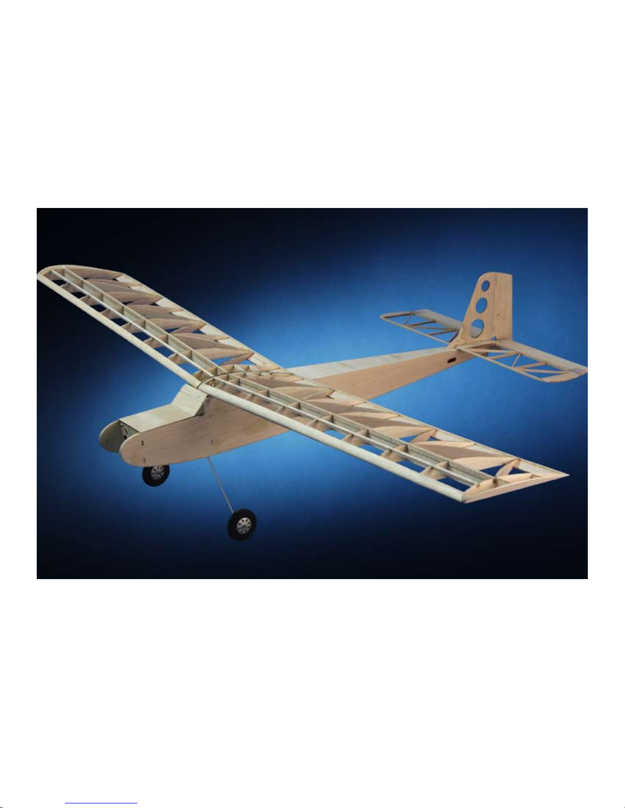
MICRO
TELEMASTER
KIT
Brentwood TN 37027 USA
Hobby Lobby International
5614 Franklin Pike Circle
Phone 866-512-1444
MADE IN THE USA
Page 2

Terminology used in this manual.
With the precision of laser cut parts and notch and tab construction, the assembly and gluing sequence
becomes very important. If components are glued in place to soon, they will not allow enough movement to install other components. When instructed to install a part, do only that. You will be instructed
to glue it when it is no longer required to be moveable.
Test Fit:
Test t and install but do not glue.
Install and glue:
Permanently install the part.
Locate and prepare:
Find the parts requested, you can locate them faster using the parts locator pages at the back of this
manual. The parts locator will direct you to the correct sheet number as well as describe the part for
easier identication. Most of the parts are supplied still in the sheet. These sheets are called the carrier
sheet and the parts are held in the carrier sheet by small breaks in the cutting line. These are called
retainer breaks and in most cases the parts can be extricated by simply exing the carrier sheet and the
retainer breaks will release the parts. In harder materials it may be necessary to use your hobby knife to
sever the retainer breaks to remove the parts. After removing the parts, a small nub may remain where
the retainer break was, this must be removed with a light swipe of sandpaper so it will not interfere with
the parts t.
Adhesives:
There are four primary types of adhesives recommended for constructing your model. They are CyanoAcrilate (referred to as CA) in all viscosities, Aliphatic Resin Glue (carpenters glue), Polyurethane glue
referred to as PU and Epoxy. CA is the primary adhesive to use however there are times when it is not
the best choice.
They are:
1. When you need more time to carefully position a part than a fast setting adhesive will allow.
2. When attaching plastic such as a windshield (Use Pacer formula 560 here).
3. When gluing laser cut aircraft grade plywood’s. The microwave set adhesives used in aircraft grade
plywood does not ablate well under a laser beam. As a result it burns the wood bers near by leaving
a charred edge. Fast setting CA adhesives do not allow time for the adhesive to penetrate this layer of
char and bond to the wood ber underneath. Use a slower setting adhesive such as Aliphatic Resin for
maximum strength use Epoxy on aircraft grade ply parts. Lite Ply’s do not use this type of adhesive and
do not suffer from this problem.
To apply thin CA we recommend the Dave Brown pipets available from Hobby Lobby. Be sure to stretch
the end (pull it with a pair of pliers) to a thin applicator tip, as they are not supplied in this conguration.
REV C
1
Page 3
Fuselage Assembly
c 1
c 2
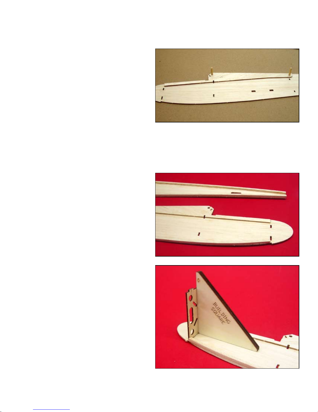
Glue the fuselage doubler (FD) to fuselage
side (FS). Use the 1/8” dowel in the holes at
the top to align the two parts but do not allow
the dowel to get glue on it. Make a LEFT and
a RIGHT fuselage side assembly.
NOTE: the 1/8” dowel will ultimately be used
when joining the wing however until then it
will be used as an alignment tool on several
assemblies.
Glue a 1/8” square balsa stringer to the bottom and top inside corners of each side. The
top corner stringer should start at the aft end
of FD and terminate at the tail and the bottom
corner stringer should start at the back of F1
and terminate at the tail.
ABOVE: The fuselage doubler (FD) is being installed onto the fuselage side (FS) using the 1/8” dowels as an alignment aid. The
dowels will be removed after the doubler is tack glued to the fuselage
side.
BELOW: The corner stringers of 1/8” square balsa have been at-
tached. You may want to soak the rst four inches of the bottom
stringer to aid in making the bend at the front if the stringer is to
stuff.
c 3
Start with the right fuselage side, glue F1 in
the slots provided, use the Building Square to
insure that F1 is at 90º to the fuselage side.
ABOVE: The building square is used to insure that F1 is square to
the fuselage side. Use this tool to install all the formers.
1
Page 4
c 4
Glue F2 in the same manner.
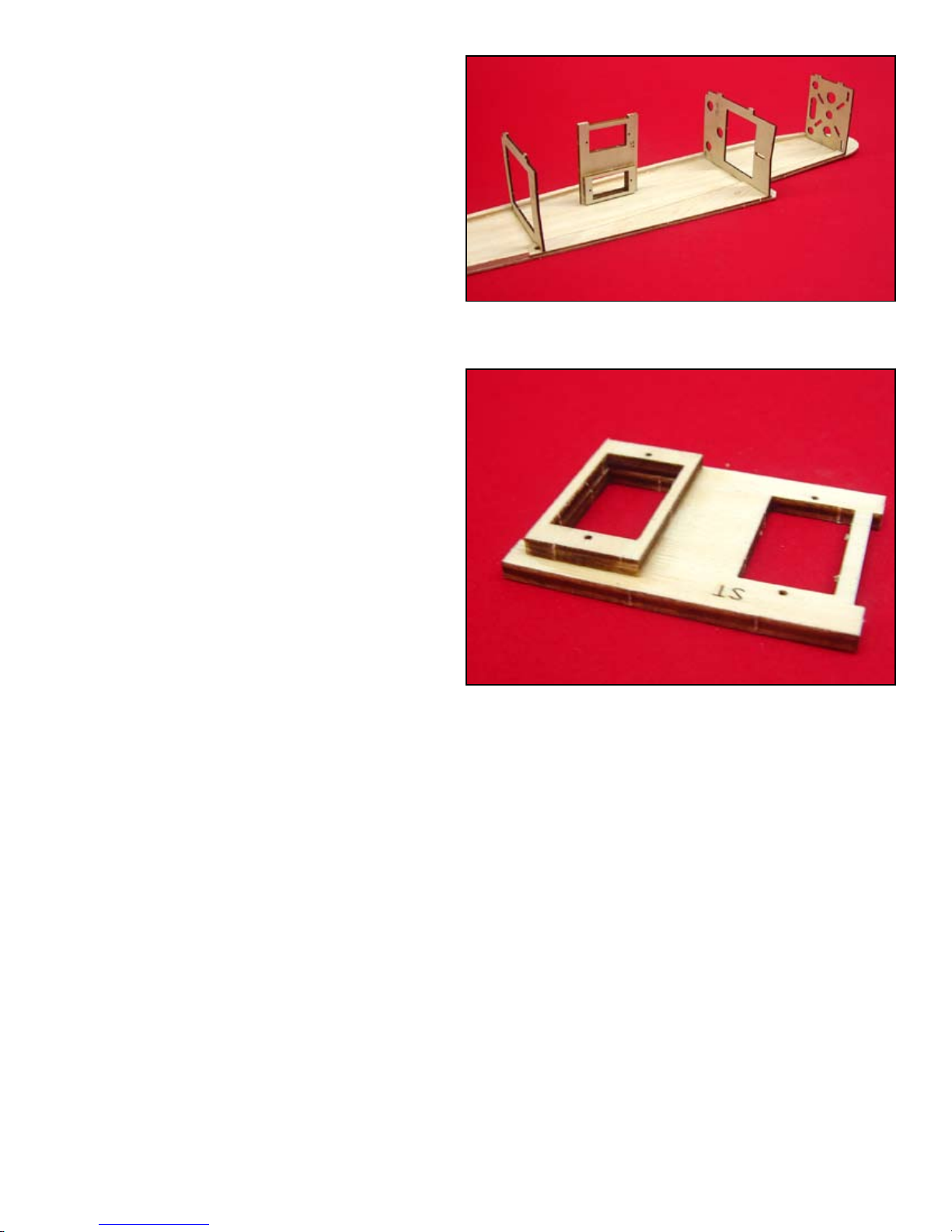
ABOVE: The right fuselage side has F1, F2, F3 and the servo tray
installed and is ready for the left side to be installed.
c 5
c 6
c 7
c 8
c 9
The servo tray (ST) requires some prefabrication before installing it into the fuselage. To
facilitate a straight through criss cross pushrod installation, one servo is elevated by 1/8”
by installing ST-B to one of the servo openings. It makes no difference which one but
ST-B must be on top of the servo tray when
installed. Glue ST-B to ST and then install
the ST assembly to the fuselage side. Use the
square to insure it is at 90º to the fuselage
side.
Glue F3 to the fuselage side in the same manner.
Test t the left fuselage side to the right side
assembly. When satised that everything will
t, glue the two sides together.
Glue a 1/8” square balsa brace to the back of
F1 to support the bottom sheeting when installed.
Use heavy thread and CA to bind the landing
gear to the landing gear mount (GM) in three
places. Keep the threads neat and compact.
Note the three holes in F2, they will allow the
threads to protrude through F2 without inter-
fering with the t of F2 and GM. Glue the GM
assembly to F2.
ABOVE: One of the servo openings is raised by 1/8” to accommodate a straight linkage between the servo and the moveable
surfaces. This simplies the push rod assembly and installation.
c 10
Temporarily pull the tail section together.
Note that both sides bend the same. If not, cut
saw kerfs in the stiff side to weaken it. This
will make it easier to nish installing the bottom sheeting.
2
Page 5
c 11
c 12
Carefully align the fuselage bottom sheeting (FB) with the forward fuselage assembly
and glue it from the F1 back to F2. Pull the
tail section together and glue it. Work your
way from aft of the landing gear to the tail
with glue making sure the sides conform to
the shape of the bottom sheeting. Glue in the
bottom braces (FBB) roughly in the locations
indicated on the plans.
Glue HMB to the fuselage assembly at the
back of the hatch opening. Install one of the
two magnets into the hole provided at the center of HMB.
2
1
c 13
c 14
c 15
c 16
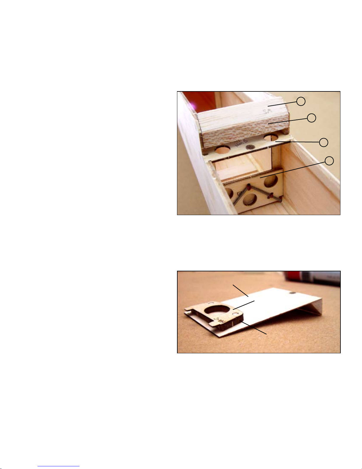
Glue a piece of 1/4” triangle stock into the
notch provided in FD at the windshield location. Refer to the plans for correct position.
See #1 in photo at right.
Glue the windshield (WS) to the fuselage just
above the ¼” triangle stock. See #2 in photo
at right.
Use the 1/8” dowels to align the hatch (HA)
and the balsa spacer (HA-B) and glue the
spacer to the hatch. Do not get glue on the
dowels.
Once again using the dowels for alignment,
glue HA-C to spacer HA-B.
3
4
ABOVE: The 1/4” triangle stock (#1) has been glued into the notch
provided and then the windshield (#2) is glued to that and the fuselage. Below that (#3) is the hatch mounting bracket (HMB) with a
1/16” x 3/16” magnet installed in it. The magnet must be ush with
the top of HMB. The landing gear mount (GM) has been installed
to F2 with the landing gear attached with CA and thread.
HA
HA-C
c 17
Install the remaining magnet into the hole in
HA. Note the correct polarity and make the
magnet ush with the bottom of the hatch.
c 18
Place the hatch assembly on the fuselage and
test t the 1/2” triangle stock. You will need to
relieve some material from the triangle stock
to clear the magnet, then glue the triangle
stock to the back of the hatch.
c 18
Sheet the top of the fuselage from F3 to the
tail with the 1/32” x 3” sheet of balsa, cross
grain.
HA-B
ABOVE: The hatch assembly shown here upside down, note the
magnet at the rear and the 1/2” triangle stock. The magnet should
be ush with the bottom of the hatch.
3
Page 6
This concludes the basic assembly of the fuselage. The wing mounting bracket will be install into the
fuselage later after the wing has been assembled and the wing attachment magnets have been installed
into the wing.
STABILIZER ASSEMBLY
c 1
c 2
c 3
c 4
c 5
c 6
c 7
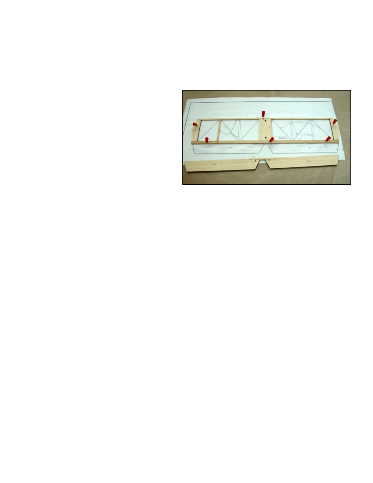
Place the stabilizer plans on the work bench
and cover them with wax paper. Place a piece
of 1/8” x 1/4” balsa aligned over the trailing
edge and trim the ends to the plans. Secure it
in this position with pushpins.
Glue the stabilizer tips (ST) to the trailing
edge and secure with pushpins.
Glue the stabilizer plate (SP) to the trailing
edge.
Cut and glue a 1/8” square balsa stick for the
leading edge. Glue it to ST and SP.
Cut, install and glue the 1/8” square ribs
Cut, install and glue in the 1/16” x 1/8” balsa
angled ribs.
Remove this assembly from the plans and
sand out any irregularities on both sides.
ELEVATOR ASSEMBLY
c 1
Place the elevator halves (EV) and pin in
place. Glue the 1/8” x 1/8” x 2” basswood
joiner in the notch provided.
VERTICAL FIN ASSEMBLY
c 1
The vertical n is supplied in two parts (VF),
glue the two together and sand at.
4
Page 7
WING ASSEMBLY
c 1
c 2
c 3
c 4
c 5
Place the wing plans on the building bench
and cover them with waxed paper to protect
them from glue.
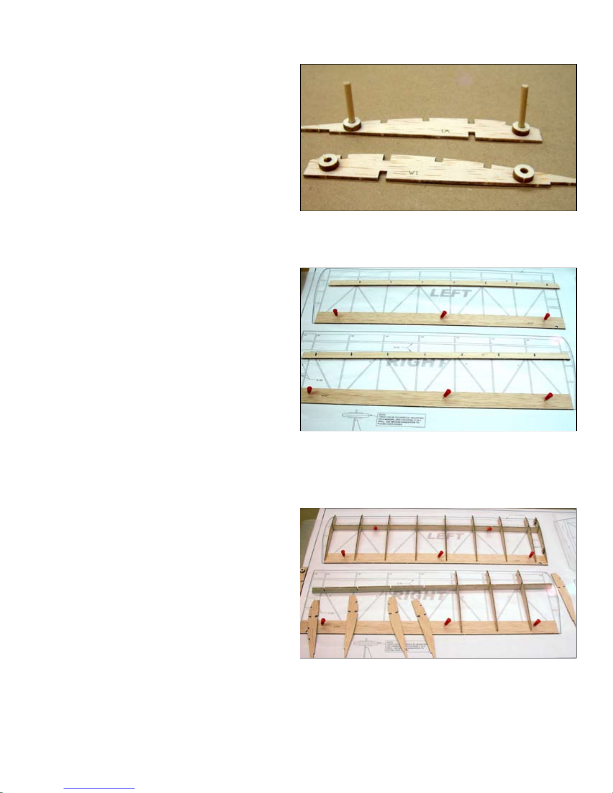
Locate W1 and W1-B (the little donuts on the
1/8” sheet) and glue a W1-B to the 1/8” holes
in W1. Glue them on opposite sides to make
a left and a right root rib. These holes will be
used later to align the wing panels. Use the
1/8” dowel to align W1 and W1-B but do not
allow the dowel to get glue on it.
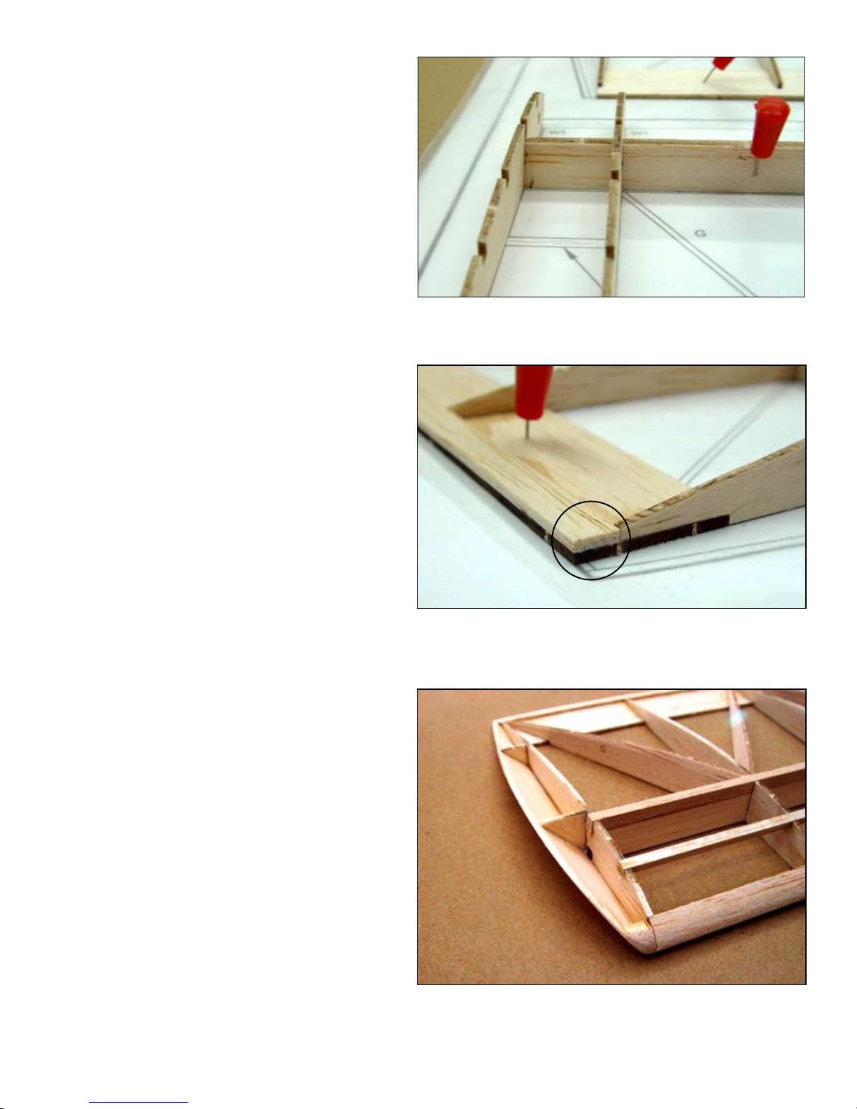
Align WTEP to the plans and pin in place.
Prepare all remaining ribs and the bottom spar
(WBS). Note the root end of WBS and install
W2 and all W3’s into the notches in WBS.
Note that W1 and W2 have extra notches for
the 1/8” square balsa. W1 and the W3 at the
wing tip will be installed later.
Place the spar and rib assembly into position
over WTEP. Make sure the ribs are fully engaged in the notches in WTEP. Align the ribs
with the plans and glue them to WTEP only at
this time. Pin WBS in position to the plans.
ABOVE: The 1/8” dowels are used to align W1-B with the holes in
W1 and then removed before gluing. At the top is the right wing W1
assembly and at the bottom the left wing W1 assembly.
ABOVE: Here both wings are being assembled at the same time.
WTEP has been pinned to the workbench and the bottom spar SP-B
has been prepared to receive the ribs.
ABOVE: At the top of the photo, the ribs have been installed onto
the bottom spar and this assembly has been glued to the wing trailing edge plate (WTEP). At the bottom of the photo, ribs are being
installed onto the bottom spar.
5
Page 8
c 6
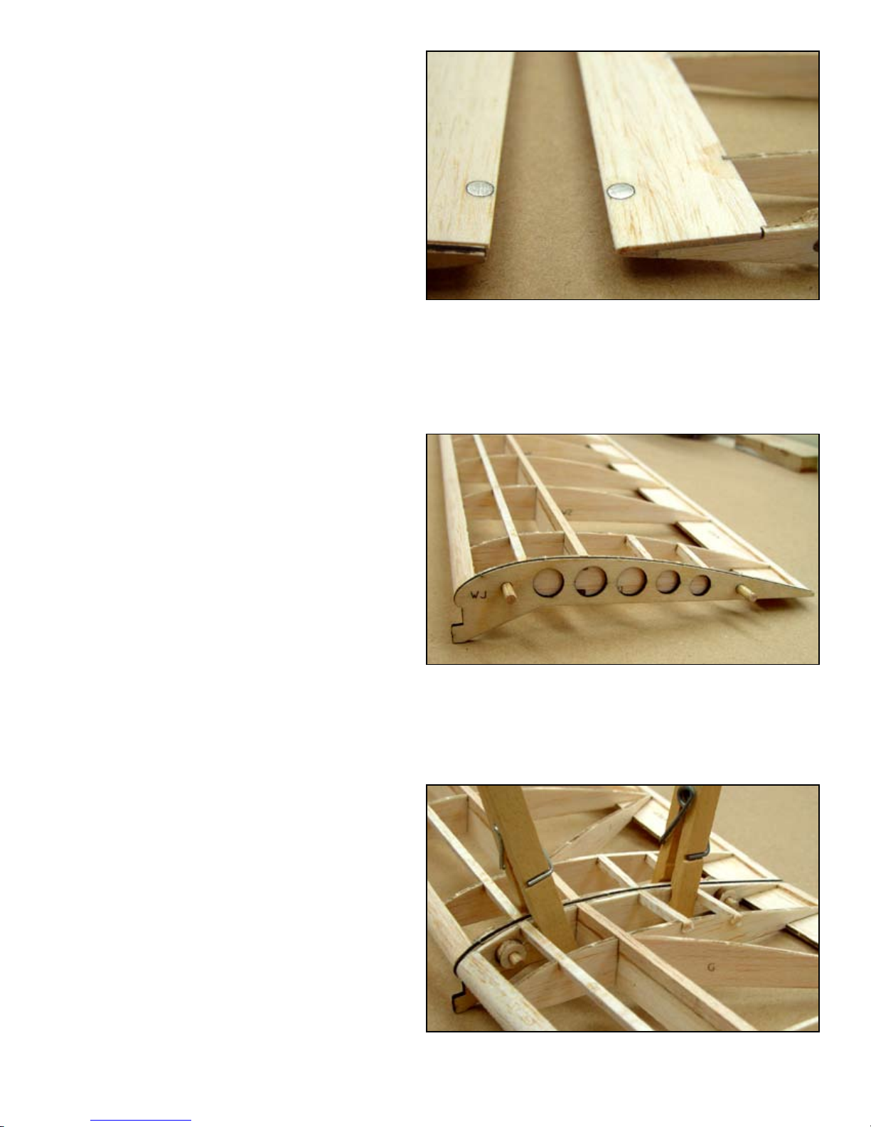
Install and glue the root rib (W1) and the tip
rib (W3) to WTEP and SP-B. Use a straight
edge at W1 to assure it is straight, as it will in-
terface with the opposite wing panel on nal
assembly.
c 7
c 8
c 9
c 10
c 11
Apply a liberal bead of glue to the top of the
bottom spar (SP-B) and install 1/8” x 3/16”
balsa stick for the top spar. Trim it ush at
both ends.
Place the leading edge, a ¼” x ½” balsa stick
in place against the leading edges of the ribs
and glue in place. Trim each end ush with
the ribs.
Install and glue a 1/8” square balsa stick in
the notches provided between the spar and the
leading edge.
Install and glue 1/8” square balsa pieces into
the notches provided in W1 and W2.
Install and glue the diagonal ribs. Sand a small
chamfer on the leading and trailing edges for
additional glue land. You may have to bow
them slightly to get them in but they should
be straight when installed.
ABOVE: The root rib (W1) is installed. Note that W1 must be canted
to conform to the angle in the bottom spar (SP-B) This is to accommodate the dihedral required.
ABOVE: The 1/16” x 1/4” trailing edge strip has been in-
stalled. Make sure the trailing edge is held at against the
building board when glue is applied.
c 12
Plane or sand a bevel into the bottom edge
of the wing tip (WT). Place it into position
against the tip rib W3. Place the large wing
top gusset between W3 and WT and glue it
in position. Glue the second gusset into position. Glue the ½” long section of 3/8” triangle
stock at the leading edge between WT and the
leading edge.
c 13
Install and glue a balsa 1/16” x 1/4” trailing
edge doubler to the trailing edge of WTSB.
Bevel the outboard end and run it all the way
out to WT.
ABOVE: Wing tip installation, note the 1/4” triangle stock ller at
the leading edge.
6
Page 9
c 14
Plane and sand the leading edge to contour
with the ribs using the included leading edge
template as a guide.
c 15
c 16
c 17
c 1
c 2
Glue in two 1/16” x 3/16” magnets in the
holes provided in the trailing edge.
Sand the trailing edge to contour with the
ribs.
Sand the root rib perfectly at in preparation
for joining the wing halves.
ABOVE: The wing retaining magnets installed in the bottom of
the trailing edge.
JOINING THE WING PANELS
Cut two 1/8” x 3/4” dowels and install them
into the holes provided in the wing hook
(WJ). Let them protrude equal amounts on
both sides of WH and glue them.
Glue the wing hook assembly to one of the
wing panels using the dowels to align the
two assemblies. Make sure WH is snug up
against the root rib.
c 3
Glue the remaining wing panel to this assem-
bly. When the two root ribs are at up against
each other, the dihedral will be correct. Use a
clamp to insure good contact between the two
panels and that both spars are glued to WH.
ABOVE: The wing hook (WJ) has been glued onto the right wing
panel using the 1/8” dowels to align the two.
BELOW: The two wing panels are glued together with WH and
cloths pins are used to clamp the assembly together.
7
Page 10
FINAL ASSEMBLY AND COVERING
c 1
c 2
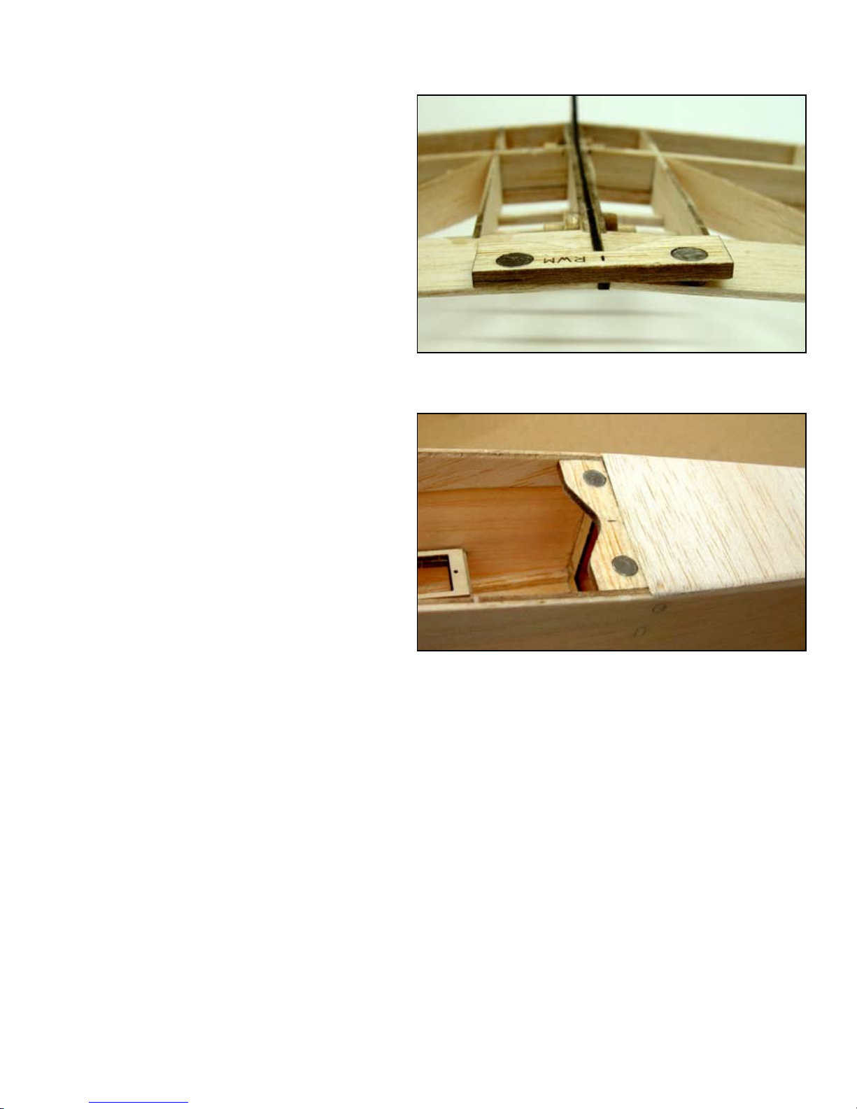
Place the wing assembly upside down on the
bench and place the rear wing mount (RWM)
over the magnets. Place one of the 1/8” x 1/4”
magnets in each of the holes provided. Make
sure the magnets attract. Use a felt tip marker
to mark the top of each magnet and RWM.
The marked side of each magnet and RWM
must be installed face down in the fuselage.
Without removing the magnets, glue them to
RWM.
Glue the RWM and magnet assembly into
the fuselage just in front of F3 as sown in the
photo. remember the side that was up on the
wing must face down in the fuselage.
ABOVE: RWM is placed over the wing magnets and the 1/4” magnets are installed with the correct polarity. This assembly is then
installed into the fuselage (BELOW) with the marked side down.
For lightest weight and best ying, cover your model with a lightweight covering designed for park yers. This will not only yield a better ying model but also be much less likely to produce warps in the
light weight structure.
Cover the fuselage and empennage separately and assemble them after they have been covered. Support
the fuselage at on the bottom (not on the gear) and install the stabilizer. Check that each trailing edge tip
is the same distance from the center of F2 and that both tips are the same distance off of the bench. When
these conditions have been met, glue the stabilizer in place. Remove the covering from the area where
the vertical n will mount on top of the stabilizer and glue the vertical n to the stabilizer in the slots
provided. Use the building square to insure the n is at 90 ° to the stabilizer.
Hinge the moveable surfaces with hinge tape or covering material. Install the elevator horn (EVH) on the
left elevator and the rudder horn (RUH) on then right side of the rudder in the slots provided.
8
Page 11
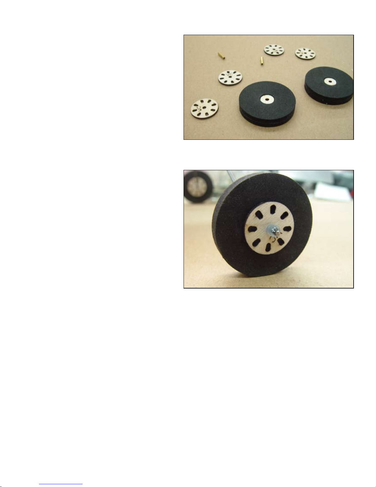
WHEEL ASSEMBLY
c 1
c 2
c 3
c 4
Install a 3/32” x 3/8” brass tube into one of
the wheel covers (WC). Place a wheel hub
(WH) down over the brass tube and glue it
to the wheel cover.
Use a contact adhesive such as 3-M 77 spray
glue to spray one side of all four foam tires.
Slide one of the tires down over the wheel
hub with the glue side up. Slide another tire
down over the wheel hub with the glue side
down. This will become one tire. Repeat this
process for the second tire.
Glue the tire assembly to the wheel cover assembly with thick CA. Then glue on the remaining wheel cover with thick CA.
Cut four pieces of silicone fuel tubing about
3/32” long. Place one of these on each axle
of the landing gear just short of the bend.
These will be the inner wheel collars. Place
the wheel on the axle and then another piece
of fuel tubing. Use a drop of thick CA to
secure the outer collar to the axle.
ABOVE: The wheel components laid out ready for assembly.
BELOW: the assembled wheel installed on the axle. Note the bead
of CA used to retain the silicone wheel collar.
BALANCE
Almost as important as the CG, is the lateral balance. Make a piece of string with about a 10” loop in it.
Place the loop around the wing and tape the string dead center on top of the wing. Now ip the wing over
and let it hang from the string loop. Observe the heavy wing and add weight to the high wing until the wing
hangs level. Glue this weight permanently to the high wing.
If at all possible, obtain the correct CG by moving the battery or receiver without adding weight. If additional weigh is required, place as far forward or aft as possible to minimise the amount required. In most
case additional weight will not be necessary.
Set your surface throws up for 5/8”left and right on the rudder and 1/2” up and down on the elevator.
9
Page 12

PART LOCATOR
Part # Qty. Sheet # Size Material Usage
EV 2 6 1/8” X 3” X 18” BALSA Elevator
EVH 1 5 1/32” X 2-1/2” X 5-1/2” AC PLY Elevator horn
F1 1 1 1/16” X 4” X 36” BALSA Fuselage former #1
F2 1 1 1/16” X 4” X 36” BALSA Fuselage former #2
F3 1 1 1/16” X 4” X 36” BALSA Fuselage former #3
FB 1 2 1/16” X 4” X 36” BALSA Fuselage bottom
FD 2 2 1/16” X 4” X 36” BALSA Fuselage doubler
FS 2 4 1/16” X 4” X 36” BALSA Fuselage side
G 14 2 1/16” X 4” X 36” BALSA Geodetic rib
GM 1 7 1/8” X 2” X 4-1/2” LITE PLY Gear mount
HA 1 5 1/32” X 2-1/2” X 5-1/2” AC PLY Hatch
HA-B 1 6 1/8” X 3” X 18” BALSA Hatch part B
HA-C 11 5 1/32” X 2-1/2” X 5-1/2” AC PLY Hatch part C
HMB 1 1 1/16” X 4” X 36” BALSA Hatch mounting bracket
LGF 1 2 1/16” X 4” X 36” BALSA Landing gear faring
ND 1 3 1/16” X 4” X 36” BALSA Nose doubler
ND 1 2 1/16” X 4” X 36” BALSA Nose doubler
RU 1 9 3/32” X 3” X 9” BALSA Rudder
RUH 1 5 1/32” X 2-1/2” X 5-1/2” AC PLY Rudder horn
RWM 1 6 1/8” X 3” X 18” BALSA Rear wing mount
SM 1 7 1/8” X 2” X 4-1/2” LITE PLY Servo mount
SP 1 6 1/8” X 3” X 18” BALSA Stabilizer pad
SP-B 2 6 1/8” X 3” X 18” BALSA Spar bottom
ST 2 6 1/8” X 3” X 18” BALSA Stabilizer tip
STB 1 7 1/8” X 2” X 4-1/2” LITE PLY Servo mount part B
TS 1 8 3/32” X 1-1/2” X 6” AC PLY Tail skid
VF 2 9 3/32” X 3” X 9” BALSA Vertical n
W1 2 3 1/16” X 4” X 36” BALSA Wing rib #1
W1-B 4 6 1/8” X 3” X 18” BALSA Wing rib #1 part B
W2 2 3 1/16” X 4” X 36” BALSA Wing rib #2
W3 14 3 1/16” X 4” X 36” BALSA Wing rib W3
WC 2 1 1/16” X 4” X 36” BALSA Wheel covers
WH 1 8 3/32” X 3” X 9” BALSA Wing hook
WS 1 9 3/32” X 3” X 9” BALSA Windshield
WT 2 4 1/16” X 4” X 36” BALSA Wing tip
WTEP 2 3 1/16” X 4” X 36” BALSA Wing trailing edge plate
10
Page 13

Brentwood TN 37027 USA
Hobby Lobby International
5614 Franklin Pike Circle
Phone 866-512-1444
 Loading...