

Hobby 380 TB De Luxe, 440 SF De Luxe, 420 KB De Luxe, 400 SF De Luxe, 460 UFe De Luxe Operation Manual
...
Operation Guide Camper
Version 01/2011
GB

Dear Camper,
Congratulations on the purchase of your new HOBBY camper. The trust you have placed in us is both
an incentive and an obligation to continuously implement new ideas, technical innovations and ne
touches to make our campers even better. Our fully tted and highly sophisticated models enable us
to offer you the perfect setting for the most enjoyable days of the year.
Please read this manual carefully, even if you have been driving a camper for a longer period of time. It
will help you to avoid operating errors and damage to the vehicle and its equipment. Correct handling
of all technical details will increase your driving comfort and maintain the value of your camper.
If this user manual should be unable to provide the required assistance, a close, pan-European network of dealers is available for further help. Take advantage of your authorised dealer's experience
and technical knowledge - we recommend speaking to him in detail before taking your rst trip with
your HOBBY camper.
We wish you and your fellow travellers many enjoyable trips and hope you will always have a safe
journey with your new HOBBY camper.
Your
HOBBY Camper Plant
Ing. Harald Striewski GmbH

Table of Contents
1 Introduction
..........................................................................................................................01-1
1.1 General information .......................................................................................................01-1
1.2 Markings in these operation instructions ......................................................................01-2
2 Safety
....................................................................................................................................02-1
2.1 General information .......................................................................................................02-1
2.2 Before the drive
.............................................................................................................02-2
2.3 Loading ..........................................................................................................................02-4
2.4 Handling Performance ...................................................................................................02-6
2.5 After the drive
................................................................................................................02-8
3 Undercarriage and vehicle registration
.............................................................................03-1
3.1 General information
.......................................................................................................03-1
3.2 Drawbars/Longitudinal beams ......................................................................................03-1
3.3 Safety coupling WS 3000 ..............................................................................................03-2
3.4 Front landing wheel
.......................................................................................................03-5
3.5 Locking brake facilities ..................................................................................................03-6
3.6 Overrunning equipment and wheel brakes
....................................................................03-7
3.7 Rotating stanchions .......................................................................................................03-8
3.8 Vehicle registration ........................................................................................................03-9
3.9 General inspection .........................................................................................................03-9
3.10 Fit for a Speed of 100 km/h
.........................................................................................03-10
3.11 Denition of mass
........................................................................................................03-11
4 Wheels, tires
........................................................................................................................04-1
4.1 Tires ...............................................................................................................................04-1
4.2 Tire pressure ..................................................................................................................04-1
4.3 Prole depth and age of tires ........................................................................................04-2
4.4 Rims ...............................................................................................................................04-3
4.5 Changing the tire ...........................................................................................................04-4
5 Exterior structure
.................................................................................................................05-1
5.1 Ventilation and De-aerating ...........................................................................................05-1
5.2 Entry door ......................................................................................................................05-3
5.3 Service ap ....................................................................................................................05-5
5.4 Gas-bottle container ap ...............................................................................................05-6
5.5 Toilet ap .......................................................................................................................05-6
5.6 Roof ...............................................................................................................................05-7
5.7 Guide rail for outer tent and skirting
.............................................................................05-7
5.8 Bicycle carrier
................................................................................................................05-9
5.9 Roof awning...................................................................................................................05-9
6 Interior structure
..................................................................................................................06-1
6.1 Doors, aps and drawers
..............................................................................................06-1
6.2 Pivoting TV cabinet .......................................................................................................06-3
6.3 Extendable media shelf
.................................................................................................06-4
6.4 TV mount .......................................................................................................................06-5
6.5 Tables ............................................................................................................................06-5
6.6 Conversion of seats and beds
.......................................................................................06-7
6.7 Children's beds..............................................................................................................06-9
6.8 Windows
........................................................................................................................06-9
6.9 Roof bonnets ...............................................................................................................06-12
7 Installation of electrical devices
.........................................................................................07-1
7.1 Safety tips
......................................................................................................................07-1

7.2 Control panel .................................................................................................................07-2
7.3 Electrical supply ..........................................................................................................07-11
7.4 Electrical system..........................................................................................................07-14
7.5 External circuit diagram
...............................................................................................07-16
7.6 Contact plan for the light control system ....................................................................07-17
7.7 Special Lighting
...........................................................................................................07-18
8 Water
.....................................................................................................................................08-1
8.1 General information .......................................................................................................08-1
8.2 Tanks
.............................................................................................................................08-2
8.3 Water supply ..................................................................................................................08-3
8.4 Water ushing toilet
......................................................................................................08-6
9 Gas system
...........................................................................................................................09-1
9.1 General safety rules for the use of liquid gas facilities ..................................................09-1
9.2 Gas supply
.....................................................................................................................09-3
9.3 Gas socket, external ......................................................................................................09-5
10 Built-in devices
.....................................................................................................................10-1
10.1 General information .......................................................................................................10-1
10.2 Hot-air heating ...............................................................................................................10-2
10.3 Electric auxiliary heating
................................................................................................10-5
10.4 Electrical oor heating ...................................................................................................10-6
10.5 Hot-water heating system
.............................................................................................10-7
10.6 Boiler
...........................................................................................................................10-13
10.7 Refrigerator
..................................................................................................................10-15
10.8 Gas cooker
..................................................................................................................10-18
10.9 Fume hood
..................................................................................................................10-20
10.10 Oven ...........................................................................................................................10-20
10.11 Microwave
..................................................................................................................10-22
11 Accessories
..........................................................................................................................11-1
12 Maintenance and upkeep
....................................................................................................12-1
12.1 Maintenance ..................................................................................................................12-1
12.2 Drawgear .......................................................................................................................12-2
12.3 Brakes............................................................................................................................12-4
12.4 Changing the taillight bulbs ...........................................................................................12-5
12.5 Ventilation ......................................................................................................................12-6
12.6 Upkeep ..........................................................................................................................12-6
12.7 Winter Lay Up for the Camper .....................................................................................12-11
12.8 Winter Operation .........................................................................................................12-13
13 Waste disposal and environmental protection
..................................................................13-1
13.1 The environment and mobile travel
...............................................................................13-1
14 Technical data
......................................................................................................................14-1
14.1 Tire pressure values
.......................................................................................................14-1
14.2 Weights in accordance with 97/27/EG ..........................................................................14-1
14.3 Basic equipment ............................................................................................................14-3
14.4 Technical data
................................................................................................................14-4
14.5 Possibilities for increasing loads ....................................................................................14-6
14.6 Tires and Rims ...............................................................................................................14-8
14.7 Lighting
........................................................................................................................14-10
14.8 Moulding ......................................................................................................................14-11
Index
........................................................................................................................................Ix-1

01-1
Our campers are continuously being further developed. Please understand that we reserve the
right to make changes to their equipment, shape
and technology. Therefore, HOBBY shall not be
liable for any claims arising from the contents of
this handbook. The equipment used at the time
of printing is described in this handbook and
should be transferred accordingly to the layouts
of all the different camper variations. Please
understand that we cannot describe all of the
individual variations. Your dealer will be pleased
to answer any special questions regarding the
equipment and technology of your camper.
Your HOBBY camper has been built in accordance with the latest technology and recognised
safety regulations. Despite all of these safety
measures, it is possible that people may be hurt
or the camper damaged if the safety instructions
in this handbook and the warnings posted on
adhesive labels in the camper are not followed.
1. Introduction
1.1 General information
Before the rst trip
You should certainly familiarize yourself thoroughly with the contents of this handbook; it is
much more than a reference book.
Fill out the guarantee cards for the built-in appliances in the separate instructions, and send the
guarantee cads to the respective manufacturers.
In doing so, you secure your right to a guarantee
for all devices.
HOBBY grants a 5-year guarantee
on the watertightness of the camper
in accordance with guarantee conditions. When you accept the vehicle
you will receive the guarantee booklet, "Five-Year Guarantee on Watertightness" from your HOBBY dealer.
Annual leak checks are not free of
charge. Warning: If no leak inspection
is performed, your right to the 5-year
guarantee loses its validity.
01-2
1.2 Markings in these operation instructions
Markings in these operation
instructions
The handbook explains the camper as follows
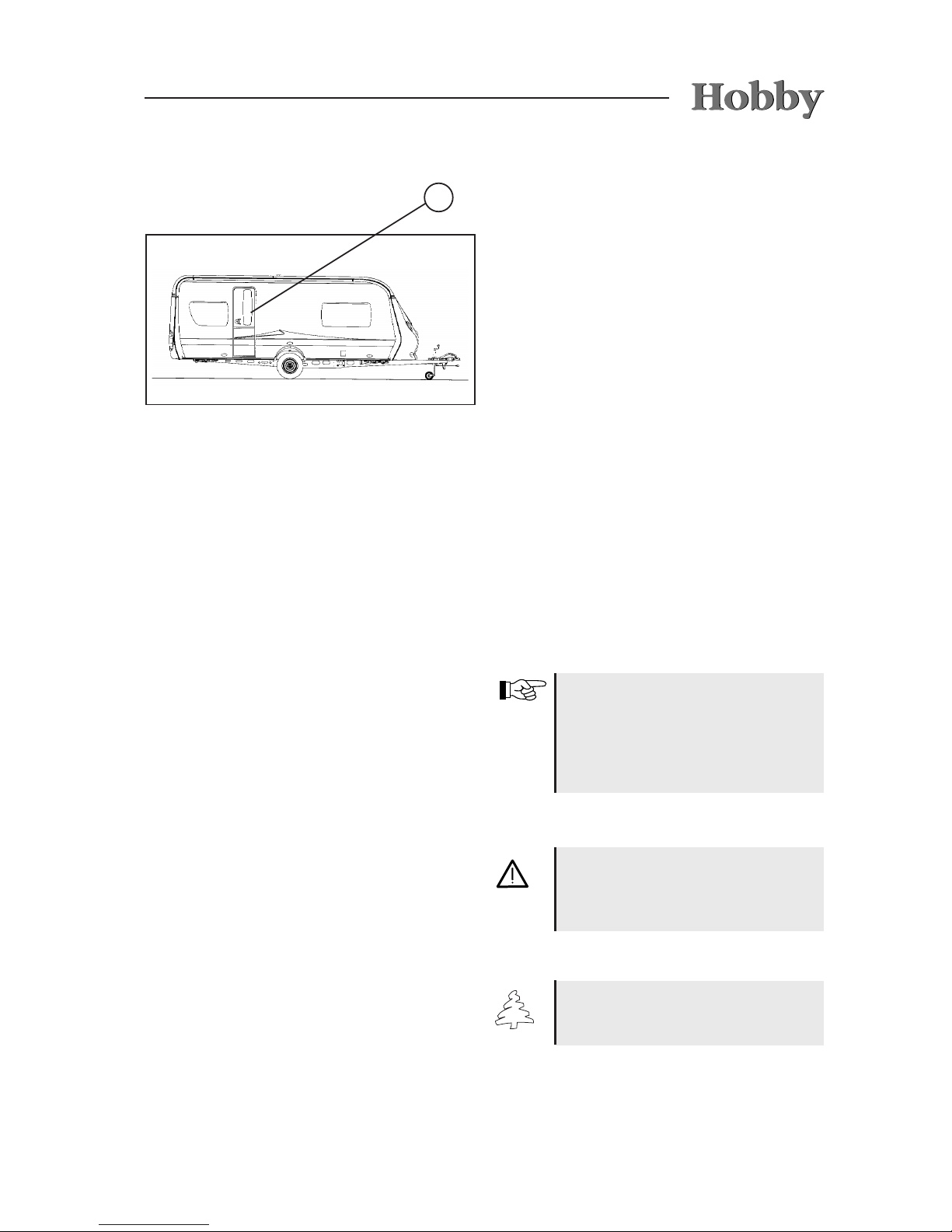
Texts and illustrations
The texts which accompany illustrations are
found directly to the right of the illustrations. Details in illustrations (here: entry door) are marked
with position numbers j.
Lists
- Lists are based on key points and are pre ceded by a dash.
Procedural guidelines
• Procedural guidelines are also based on key
points and begin with a round sentence
opener.
Guidelines
Guidelines point out important details
which ensure the trouble-free function of the camper and its equipment.
Please bear in mind that various models have different equipment; therefore, varying descriptions are possible.
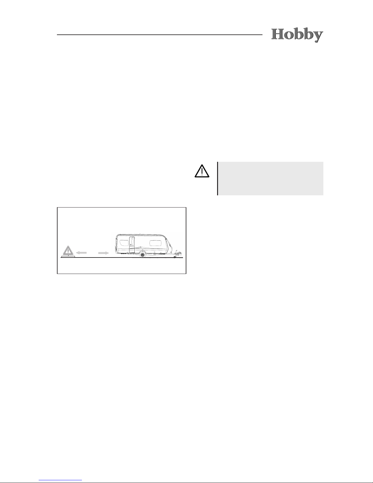
Warnings
Warnings point out dangers which, if
they are not followed, could cause
damage to equipment and/or injury
to persons.
Environmental tips
Environmental tips show possible
ways to reduce strain on the environ ment.
1

02-1
Warnings and information labels are
attached both inside and outside the
vehicle. These are meant for your
safety and may not be removed.
Keys
The following keys are provided with the camper:
- Two keys which t into the following locks:
- entry door,
- service aps,
- toilet ap.
- gas-bottle container lid
- fresh-water tank lid
Emergency equipment
To be prepared for an emergency, you need at
lest three basic items of rescue equipment (rst
aid kit, warning triangle and re extinguisher)
which you should carry at all times and know
how to use.
- frist aid kit
- warning triangle
- high-visibility vest
Fire prevention measures
• Never leave children unattended in the
vehicle.
• Keep ammable materials away from all heating and cooking appliances.
• Changes to the electrical system, gas system
or built-in devices may only be carried out by
professional, authorised workshops.
• Place a re extinguisher at the main entry
door.
• Ensure that everyone is familiar with the guidelines on the re extinguisher.
• Place a re cover near the gas cooker.
• Keep all escape routes clear.
• Ensure that everyone is familiar with the re
prevention measures on site.
2. Safety
2.1 General information
100 m
02-2
Exterior
Go around the carriage and prepare for the drive
as follows:
Preparation of the vehicle
• The camper must be hitched properly (see
guidelines for the safety hitch WS3000).
• Release the handbrake of the camper and
attach the contact-breaking cable to the cou pling ball of the base vehicle.
• Tighten the tire bolts after driving the rst 50 km.
• Plug the 13-channel plug in the socket of the
base vehicle.
• Inspect the vehicle lighting.
• Turn the winding stanchions and the front
landing wheel upward and secure them.
• Close gas bottles (heating is forbidden while
driving).
• Empty the waste water tank.
• Close gas bottle compartment.
• Adjust outer mirrors on base vehicle.
• Check camper's tire pressure (see tire
pressure table).
• Close all windows.
• Close the service aps.
• Close and rmly lock roof bonnet.
• Shut off the light on the outer tent.
• Close and secure entry door.
• If necessary, pull the electrical cord to the
230 V mains supply out of the exterior socket.
• If necessary, pull the television antenna in-
ward as far as possible or fold over the
satellite dish.
Fighting a re
• Evacuate all passengers immediately.
• Close the main shut-off valve on the gas
bottle as well as the shut-off valves on gas powered appliances.
• Shut off the electrical supply
• Sound alarm and call the re department.
• Only ght the re yourself if this is possible
without risk.
2.2 Before the drive
As the owner and driver, you are responsible for
the condition of your vehicle. Therefore, you must
note the following points:

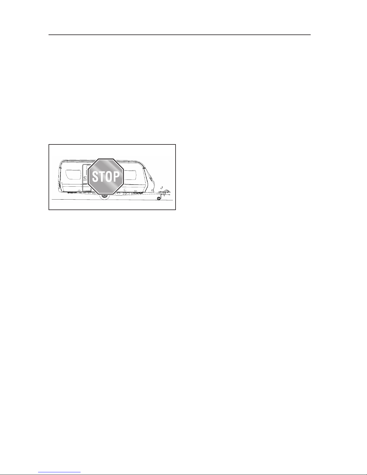
02-3
Staying in the camper during the
drive is prohibited by law!
• If necessary, secure the roof load and lash it
to prevent slippage.
• If necessary, secure all bicycles and lash them
to prevent slippage, ensuring that they do not
cover any lighting equipment.
• In winter, the roof must be free of snow and
ice before you begin to drive.
Interior
You must also prepare the interior of the vehicle
Preparing the interior:
• Sort all loose objects and store them in their
respective compartments.
• Store heavy and / or voluminous objects (e.g.
radio, outer tent, beverage cases) safely
before you start your journey, securing them
to prevent them from shifting.
• If necessary, redirect refrigerator to 12-volt
operation.
• Shut off all interior lighting.
•
Ensure that all uids, including those in refrig-
erator, are secured to prevent leakage.
• Close main valve on gas container and quick-
close valves on all gas-powered appliances.
• Close all doors (incl. refrigerator door),
drawers and aps tightly.
• Lock the central lock on the kitchen drawers.
• Latch the sliding door.
• Lower table and secure it.
• Secure the extendable media shelf, media
oval or TV mount.
02-4
2.3 Loading
Rules for loading:
• Spread the load evenly between the left and
right-hand side of the camper. Heavy or bulky
objects belong in the lower storage compart-
ments and near the axle.
• If your camper has a tandem axle: distribute
the centre of weight between the two axles.
• Never focus the load in the camper to the rear
(danger of swinging back and forth).
• Heavy objects should be stowed securely to
prevent them from slipping.
• Lighter objects (clothing) should be stowed in
the wall cupboards.
• You may not always be able to follow the re-
recommended stowing arrangement, because
storage possibilities are distributed throug
hout the entire interior of the camper. If ne cessary, stow heavy objects in the base
vehicle.
• Store baggage in the interior in cupboards
and storage compartments.
• Secure doors and aps.
• Check the technically permissible maximum
weight and the axle load(s) after you have
nished loading.
The gross vehicle weight rating in dicated in the vehicle documents as
well as the permitted drawbar load
may not be exceeded. Also note the
permissible drawbar load of your
base vehicle.
The lower the camper's centre of gravity, the better its driving performance
and response in curves.
The permissible maximum weight
and the permissible drawbar load
entered in the vehicle's registration
documents may not be exceeded.
02-5
Drawbar load
You will only achieve optimum driving stability
and decisively increase your safety on the road if
the drawbar load has been properly adjusted for
your combination of base vehicle and the camper being pulled. The drawbar load indicates the
power the camper's drawbar exerts on the car's
clutch.
Rules for the drawbar load:
• Set the drawbar load correctly! You can, for
example, use normal bathroom scales: use a
strip of wood (approx. 400 mm long) to po-
sition them vertically under the coupling jaw.
It may also be possible to roughly estimate
the drawbar load by means of the drawbar
load scales m integrated in the front landing
wheel, whereby the drawbar of the camper
must be in a horizontal position.
• Always check the drawbar load before you
start to drive!
• The specied drawbar load (see handbook
or type plate) and the permissible overall
mass of the base vehicle and the camper may
not be exceeded!
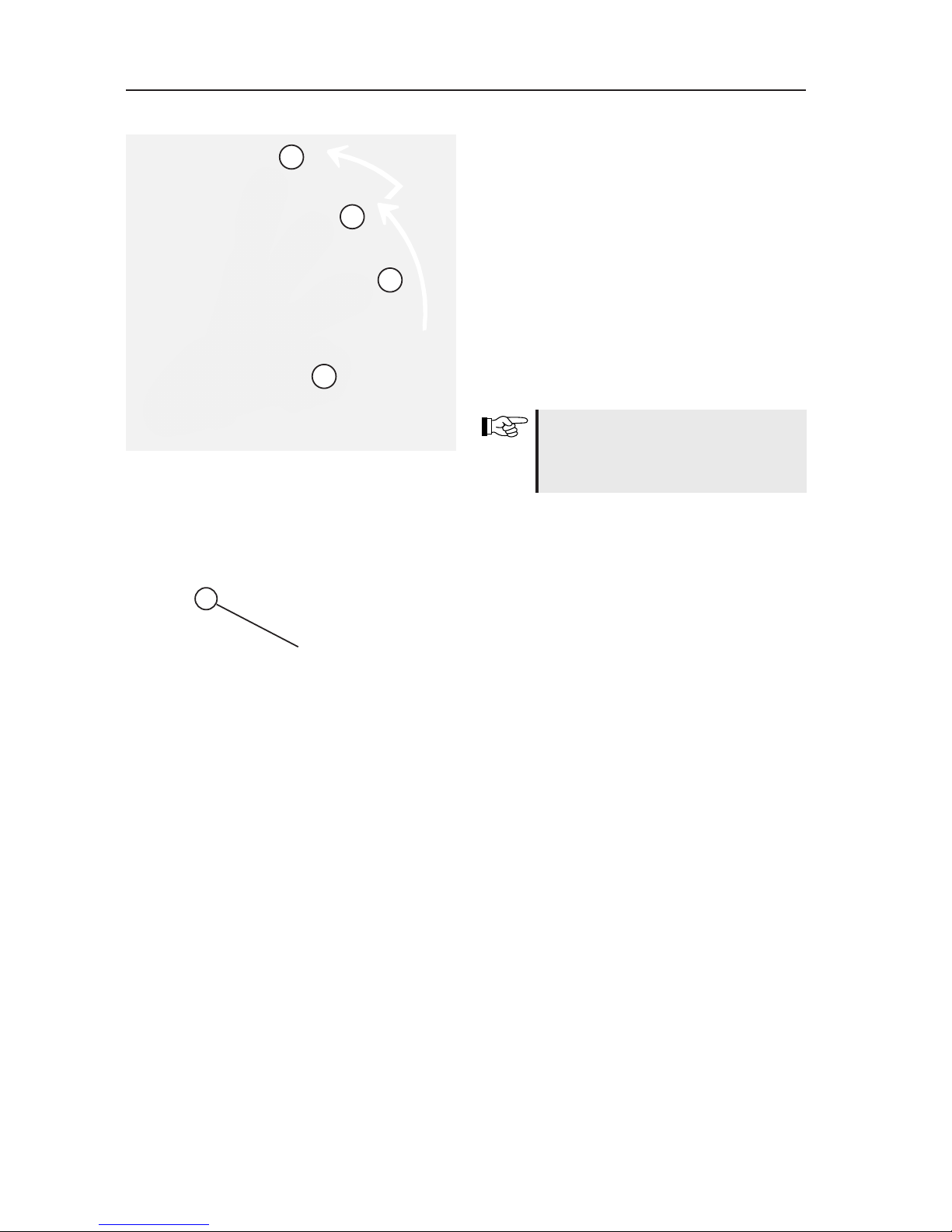
How to adjust the correct drawbar load:
1. Determine the maximum drawbar load of your
base vehicle by checking its documentation,
the type plate or the drawbar plate.
2. Your HOBBY camper has a maximum per-
missible drawbar load of 100 kg.
3. Adjust the drawbar load on the camper to the
lower of the two values by loading it careful ly. At the same time, try to make full use of
this value.
4. The lower of the two specied values for the
drawbar load, i.e. that of the base vehicle or
the camper, may not be exceeded.
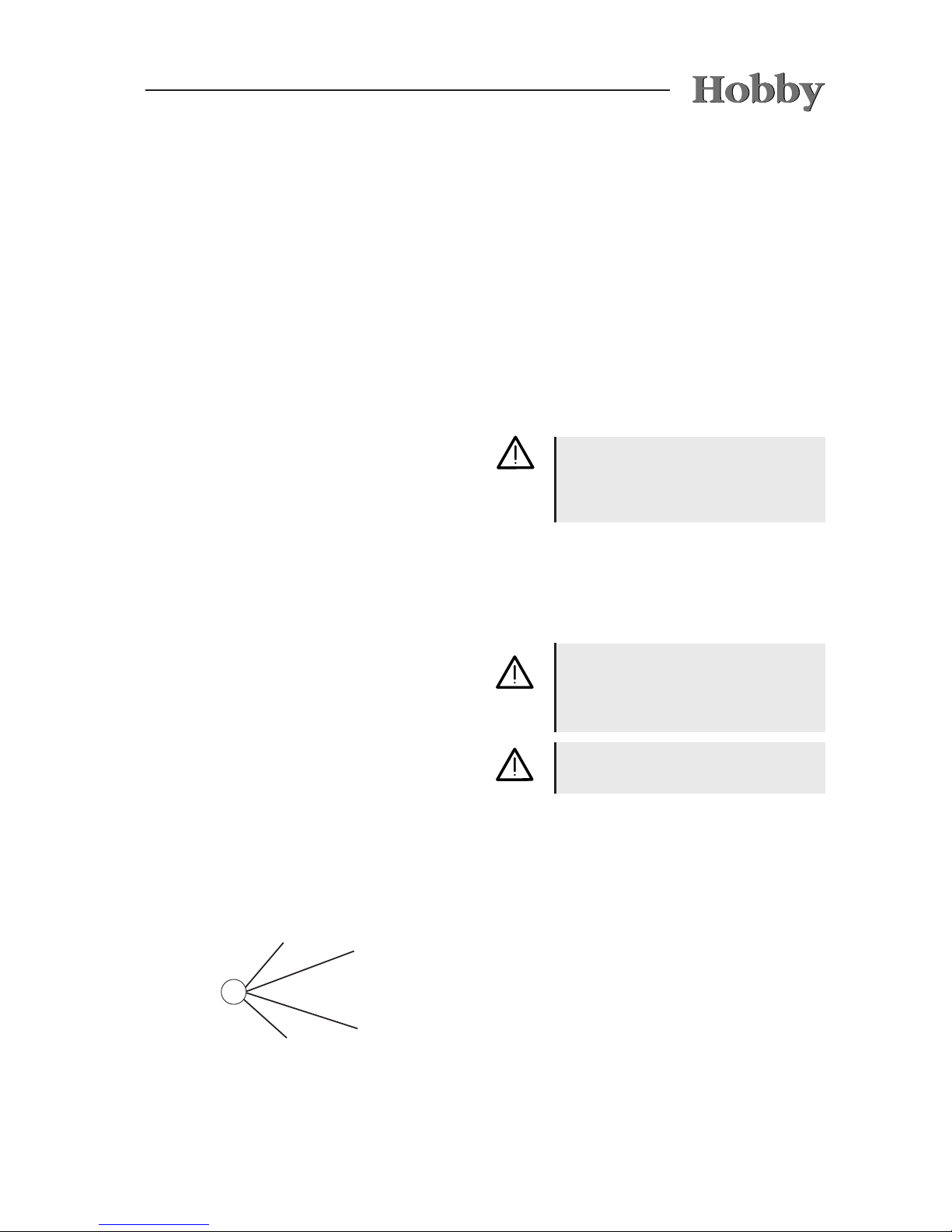
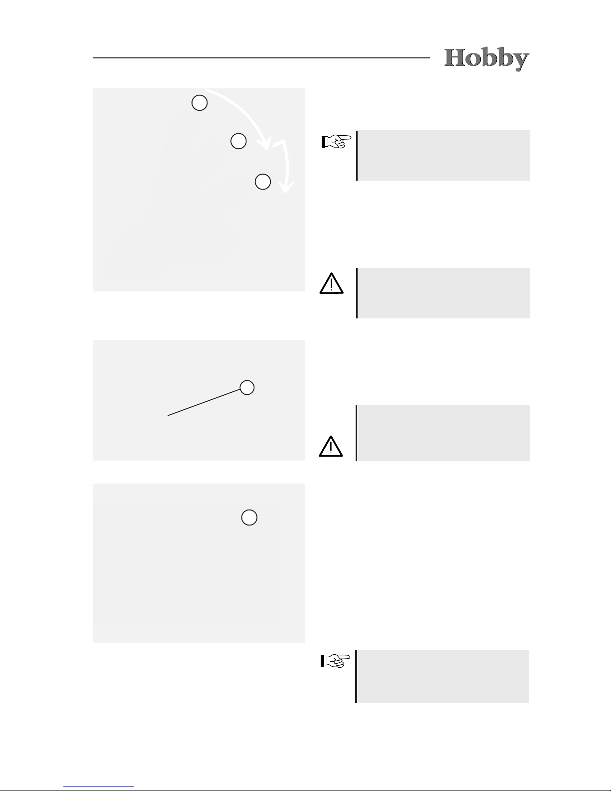
Stowage areas in the camper
- Light objects j such as towels and light-
weight laundry.
- Medium-weight objects k such as clothing,
laundry and food.
- Heavy objects l such as the outer tent, boat
motor or crates of drinks.
3
2
1
If your camper is equipped with a rear bicycle
rack, the reduction in the drawbar load created
by the bicycles must be compensated by the
rest of the load.
4

02-6
dangerous. Measure your speed from the
outset in such a manner that the carriage can
be accelerated, if necessary, without endan
gering other drivers or pedestrians.
• If the carriage moves back and forth on a
sloping road, brake carefully but rapidly if the
carriage forms a line, i.e. if it is stretched.
• Never increase speed if the carriage be-
comes pendulous.
• Do not drive down a hill any faster than you
would drive up one.
• When overtaking or being overtaken by trucks
or buses, the carriage can be caught up in air
suction. This could cause the camper to sling
or become pendulous.
Driving around curves
Your carriage is considerably longer than a car.
Rules for driving around curves
• Do not take curves too quickly or too sharply!
• Take the curve at a somewhat wider radius
when turning.
• Note that the camper can sheer out of line over
the rear.
2.4 Handling Performance
Driving
Take a test drive or a safety training course before the rst long drive to better acquaint yourself with the carriage in driving conditions.
Rules for driving
• Do not underestimate the length of the
carriage.
• Exercise special caution when driving toward
yards and through gates.
• In conditions with strong side winds, slick ice
or wet roads, the carriage could move back
and forth.
• Adjust driving speed to overall street and traf-
c conditions.
• Long, lightly sloping roads are potentially

02-7
The camper's brakes are deactivated
when you drive in reverse.
Brakes
A trailer carriage behaves differently from an individual vehicle while braking. Therefore, it is advisable (especially for inexperienced drivers) to conduct several braking tests on a suitable surface.
The braking distance for a carriage is longer than
that of an individual vehicle. The load in the cara-
van also has a signicant inuence on the braking
distance.
Rules for braking
• Note the longer braking distance on wet roads.
• When driving down mountains or steep hills,
do not use a higher gear than when driving
uphill.
• During long drives over passes, permanently
overrunning the camper can cause the wheel
brakes to heat up considerably. If necessary,
you should allow enough time to enable them to
cool down again.
Driving in reverse
Your HOBBY camper has a braking system with
automatic reverse.
It enables you to drive backwards without applying the brakes, because the
overrun coupling does not differentiate between
overrunning or reversing the camper. When you
back up the camper, you must rst overcome a
slight residual brake torque in order to activate the
automatic reverse. You can then back up the cam-
per without any difculty. The next time the camper
moves forward, the normal braking facility is then
automatically applied again.
Due to the design of the brakes, there
may be increased wear in the brake
lining during the initial break-in phase.
After having driven 500 km, the basic
setting for the brakes must be
checked by an authorised specialist and adjusted if necessary (initial
inspection).

02-8
Choosing a parking place
Rules for choosing a parking place:
• The parking place should be as horizontal as
possible.
• Check to see that the entry step is positioned
horizontally (important for refrigerator func
tion).
• Balance the lengthwise slant with the front
landing wheel.
• Balance the crosswise slant by laying appro-
priate boards or a ramp under a wheel.
Do not compensate differences in
height with the lift stanchions.
Securing the vehicle
Rules for securing the vehicle:
• Set the parking brake.
• Only extend the rotating stancions as far as
necessary so that the axle still bears part of
the weight. (The crank is clipped to the bot-
tom of the gas-bottle container.)
• Lay mats under the lifting stanchions when on
soft ground.
• Use stop-blocks to secure the wheels.
2.5 After the drive
When positioning the camper manually, only use the steering handles at
the front and rear ends of the cam-
per. Never push on the plastic parts
or the walls.
Rules for shunting
• There is a signicant blind spot in shunting,
even when the exterior mirrors are properly
adjusted.
• Use a guide when turning into difcult parking
spots.
Rules for driving in reverse
•
The camper tilts in the opposite direction in
which you steer.
• Use a guide when driving in reverse.
Shunting
Your carriage is signicantly larger than a car.

02-9
Water installation
Water left standing in the fresh water tank or the
pipes quickly becomes undrinkable.
If the camper socket has been attached to the base vehicle in a manner
conforming to standards (DIN ISO
146), the battery of the base vehicle
will not be discharged when the ignition has been switched off and you
have forgotten to switch the refrigerator from 12V operation.
Redirecting electrical devices
Rules for redirecting electrical devices
• Open the main shut-off valve on the gas
bottle as well as the shut-off valves on the
gas-powered appliances you require.
• Redirect the refrigerator from 12 V to gas or
230 V.
The water supply system corresponds
at least to the state of the art as of
03/2009 (Directive 2002/72/EC).
Therefore, check the water pipes and the fresh
water tank before each drive to ensure they are
clean. Disinfect and rinse the drinking water
facility regularly, and always before each journey.
Please empty any residual water from
the water tank before lling it with
fresh water.
A spring brake on the brake lever
ensures that the brakes will not disengage by themselves, even if the rotation direction is reversed from driving
forwards to backwards. If you have
activated automatic reverse, the brake
lever must be moved beyond the dead
centre position to its nal position.

02-10
03-1
Frame parts and axles are components of the
undercarriage. No technical modications are
allowed; otherwise, the terms of operation are no
longer valid!
For the sake of trafc safety, the vehicle undercarriage must be maintained just as conscienti-
ously as the base vehicle itself.
This maintenance
should be carried out by your HOBBY dealer. If
spare parts are required, use only the original
parts designated by the manufacturer.
Generally, campers are not suitable
for pulling by lorries or buses. If this
is done permanently, they will be
damaged.
3. Undercarriage and vehicle registration
3.1 General information
1
Preparing the mover
Almost all camper chassis have been prepared
at the factory for the subsequent tting of a
special Truma mover. Four mounting holes have
been drilled into each of the two longitudinal beams j for mounting the mover k to the model
H SE (single axle) or H TE (tandem axle). Depending on the prole of the longitudinal beam, the
size of the tires and the mounted axle, the mover
must be stabilised using an angle bracket l
which connects the mover to the axle tube.
Bent or damaged drawbars must be
replaced immediately. You are not
allowed to repair damaged components.
3.2 Drawbars/
Longitudinal beams
The main chassis beam and the towbar are con-
nected by cone washer bolts (with the exception
of the one-piece chassis). During regular main-
tenance, all of the screws must be checked and
retightened, if necessary (105 Nm).
You may neither drill into or weld onto
the chassis.
03-2
The Truma mover H SE / H TE has been type-approved and a general operating licence has been
issued for Germany. In Germany, approval is
not required by a technical support organisation
(TÜV, DEKRA). However, the general operating
licence must be kept in the vehicle at all times.
2
3
Only the Truma mover for the models
H SE and H TE may be mounted in
the existing holes.
Mounting the H SE or the H TE movers
without angle brackets l is not permitted.
It is not possible to mount the mover
H SE / H TE to any of the WLU mo-
dels, because the installation space
is blocked by the hot air ducts.
Please see your Hobby dealer for
further information or to have the
complete system mounted.
3.3 Safety coupling
WS 3000
The camper has been tted with a safety coupling
with tracking stabiliser to prevent it from beco-
ming pendulous or pitching. This system conforms to ISO 11555-1. It has been permitted for
use up to a maximum speed of 100 km/h.
Please note the additional operating instructions
and the manufacturer's safety instructions.
WARNING: A safety coupling does
not suspend the laws of physics. If
the limits (of speed and weight conditions) are exceeded, traction and
cornering force are reduced, which
then becomes the responsibility of
the driver. Therefore,
avoid elevated
risks.
It is not possible to mount the H
SE mover on the following models;
alternatively, however, the Truma SE R
standard mover can be mounted:
• 350 TB, 400 SFe (longitudinal beam
is too short; therefore, not enough
room in front of the axle)
• 540 WLU and 560 WLU (space for
mounting blocked by the styrofoam
insulating case made by Düker)
• 720 KFU, 780 WLU and all models
that can carry a load of 2,200 kg
03-3
4
3
1
2
3
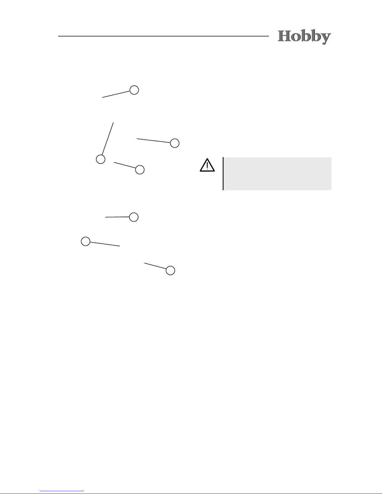
Preparation for hitching/unhitching
• To hitch and unhitch, open the tension ball
coupler (lever in position j).
When dealing with higher drawbar
loads hitching and unhitching is
simplied by the use of a support
wheel.
Hitching
• The open tension ball coupler is set onto the
coupling ball of the base vehicle.
The tension ball coupler usually closes by
applying downward pressure since the sup-
port load is
sufcient (lever in position k).
WARNING: Ensure that the metal of
your ball coupler is bright and free of
grease.
Inspection of hitch
• The ball coupling is closed when the lever
rests in position k or l and the green pin
of the hitching display m is visible.
If the WS 3000 is not properly at-
tached to the coupling ball, the
camper
can detach from the base
vehicle.
Activation of the stabilization system
• To activate the stabilization system, the
operation lever must be moved downward out
of the closed position k until it locks in l.
The spring corpus will become tense in the
process, so that contact pressure is created
on the coupling ball via the friction elements.
Afterward, the operation lever lies approxi-
mately parallel to the drawbar axle.
Shutoff of the stabilization system
• Bring the operation lever slowly upward into
the open position (position k) to shut off the
system.
Although it is possible to drive without activating the stabilizing device,
e.g. when shunting, we do not re-
commend that you do so.
03-4
Unhitching
5
Controlling the stabilizing device
Nach Ankuppeln und Aktivieren der
Stabilisierungseinrichtung kann der Zustand der
Reibelemente kontrolliert werden:
- After having hitched and activated the
stabilizing device, you can then control the
state of the friction pads:
- If the wear indicator n is in the green
(OK) zone, the friction pads are suitable for
driving.
- If the indicator is in the yellow transition
zone, the friction pads must be replaced
without delay.
- If the indicator is in the red (STOP) zone,
there is no stabilizing function. Permission to
drive at 100 km/h is immediately cancelled.
1
2
3
• Release the overrun coupling so that the
gangway bellows o are expanded.
• Release the contact-breaking cable and pull
out the 13-pole plug.
• Slowly pull the lever upwards into position k
to switch off the stabilizing device.
• Pull the lever backwards and, at the same
time, further into position j so that the
coupling opens.
• After the front landing wheel has been rotated
out, the camper can be disconnected from the
base vehicle.
If you do not plan on using the camper for a longer period of time, you
should store it with the ball coupling
closed.
6
03-5
3.4 Front landing wheel
Rotating it upwards and securing it
• Hitch the camper to the base vehicle, aligning
the front landing wheel j to the rear end of
the camper.
• Loosen the tommy screw k.
• Pull the spindle tube l up as far as possible.
• Tighten the tommy screw k.
• Turn the crank of the front landing wheel m
clockwise to raise the wheel as far as possible
and secure it to prevent it from twisting.
Before driving, always make sure
that the front landing wheel has been
rotated upwards as far as possible
and secure it.
To lower
• Loosen the tommy screw k.
• Lower the spindle tube l as far as possible
until the front landing wheel is approx. 70 mm
above the ground.
• Tighten the tommy screw k.
• Turn the crank of the front landing wheel m
counter-clockwise to lower the wheel until it
touches the ground.
• Unhitch the camper from the base vehicle
and, if necessary, lower the front land wheel
further.
1
2
3
4
4
3
2
03-6
3.5 Locking brake
facilities
The components of the brake system, especially
the overrun coupling, transmission and wheel
brakes have been checked in accordance with
the corresponding EU directives and may only
be used in the licensed combination.
If you alter or modify any components of the
brake facilities, the operation permission loses
its validity. Modications may only be made with
the manufacturer's permission.
Parking the carriage
When parking the carriage, the locking brake of
the camper must be activated.
To lock
• Pull the locking brake lever upward by the
handle j until it locks into place. The locking
brake lever is pressed into the nal position
by the gas pressure spring.
To release
• Push the hand brake forward to the starting
position.
1
When you park the camper after
reversing it, the hand brake must
be moved beyond the dead centre
position to its nal position in order to
ensure that it is fully effective.
Rapid-emergency brake
The rapid-emergency brake is combined with the
hand brake. If the camper is involuntarily discon-
nected from the base vehicle, the hand brake will
be tightened or moved beyond the dead centre
position by the traction force of the rapid-emergency brake
k
. The hand brake will be emplo-
yed and the camper will do an emergency brake.
This prevents the camper from continuing to roll
without braking after it has been disconnected.
Before driving, the rapid-emergency
brake must be fastened to the base
vehicle.
2

03-7
3.6 Overrunning equipment
and wheel brakes
Checking the overrunning
equipment
1. If it is possible to push the towbar more than
halfway (approx. 5 mm) in when the locking
brake has been activated, the braking system
must be regulated immediately by an expe-
rienced shop.
2. To check the reaction point, activate the
locking brake and push the camper back-
wards until the hand brake lever is completely
tilted. Then push the safety clutch into the
overrunning equipment. The towbar must ex-
tend into the neutral position by itself by means of the gas cushion in the hydraulic shock
absorber. Should this procedure take longer
than 30 seconds, the overrunning equipment
must be checked by an experienced shop.
Wheel brakes
The wheel brakes that have been used are drum
brakes that do not automatically adjust. They
have an automatic reverse that is sensitive to the
course you drive. The linings of the wheel brakes
are wear and tear parts; therefore, they must be
checked every 5,000 km or at least once every
year. One sure sign of strong brake lining wear
is described in the aforementioned check for the
overrunning equipment: if the safety clutch can
be pushed in more than approx. 45 mm.
The overrunning brake facility consists of the
overrun coupling, a transmission and the wheel
brakes. Should the camper bump into the base
vehicle, the overrunning brake facility ensures
that it will automatically brake. In other words,
the overrunning brake facility functions independently from the base vehicle's brake system. The
brake force that is generated depends mainly on
how intensely the base vehicle brakes and how
heavily the camper has been loaded. A shock
absorber integrated in the overrun coupling and
with a dened response threshold ensures, on
the one hand, a smooth overrun while, on the
other hand, preventing the camper from braking
if you only take your foot off the gas or change
gears in the base vehicle.

03-8
The crank for the rotating stanchions is located
at the front in the gas-bottle container. It is attached rmly to the bottom of the container.
3.7 Rotating stanchions
The rotating stanchions are located in the front
and rear under the camper.
Turning the rotating stanchions outward
• Park the vehicle as horizontally as possible.
• On soft ground, lay a sturdy mat or suitably
sized board under the rotating stanchions to
prevent the camper from sinking.
• Turn the rotating stanchions outward.
The rotating stanchions may only
be used for support, and not for
leveling out or raising.
Turning the rotating stanchions inward
• With the crank, turn the rotating stanchions
inward to the horizontal position.
• When driving downhill on a mountain pass, check to ensure that the
brakes are cooled sufciently.
• Put the base vehicle into a lower
gear and drive downhill at slow
speed.
• Stretch the trailer combination as
often as possible to avoid conti-
nuous bufng by the camper.
• Always make use of parking are-
as and passing points to give the
brakes a chance to cool off.
Please read the separately enclosed
operating manual of the axle/brake
manufacturer (Knott).
It is mandatory that the brake pads
are regularly adjusted by an authorised specialist (initial inspection after
500 km) to compensate for wear in
the brake lining and minimise brake
pedal travel on the wheel brakes
and, therefore, the overrun coupling,
keeping it as consistent as possible.
(See also 12.3 Brakes)

03-9
3.9 General inspection
In accordance with Section 29 of German Road
Trafc Licensing Regulations, your camper must
undergo a major inspection every two years. This
major inspection may be carried out by the TÜV
(Technical Inspection Authority), DEKRA Vehicle
Inspections or another accredited technical sup-
port organisation.
The following documents must be presented at
each inspection:
- motor vehicle registration certicate, Part I
- valid certicate of inspection for gas facilities,
documenting installation. The initial certicate
is located in the service package for the camper.
Vehicle ID number (FIN)
The 17-digit vehicle ID number, legible from the
right, is located either on the front right-hand
side of the forked drawbar (models 350 - 650) or
on the right-hand side of the front crossmember
(models 695/780).
Furthermore, the FIN is etched on the name
plate.
Please have your VIN at hand for any inquiries or
whenever visiting your dealer.
3.8 Vehicle registration
Every vehicle which uses public roads is subject
to registration. This includes your new camper.
You can register the camper at your local registration ofce.
The following documents are required to initiate
the registration process:
- Motor Vehicle Registration Certicate Part II
and/or Certicate of Conformity (CoC)
- insurance card
- personal identication or proof of residence
- possibly, power of attorney to have someone
else register the camper
If required, please do not forget to apply for a
„100“ speed sticker.
03-10
3.10 Fit for a Speed of 100 km/h
1. Your HOBBY camper is technically equipped
for a maximum speed of 100 km/h. Under no
circumstances may this speed be exceeded!
2. Note the permissible maximum speeds for
trailer carriages in the country in which you
are travelling!
3. Road trafc regulations in Germany were
changed on 22 October 2005. Your camper
was already set to a speed of 100 at the
factory, and this has been entered in the
camper's registration documents. Upon
request, the 100 km/h sticker will be issued
by the road trafc authority when the camper
is initially registered and attached to the back
of the vehicle.
4. The following points must be observed,
because you are responsible for adhering
to them. If they are not met, the maximum
speed for the camper is no more than 80
km/h!
a) The base vehicle must be equipped with
an anti-locking system/anti-lock device
and may not exceed an overall mass of
3.5 tons.
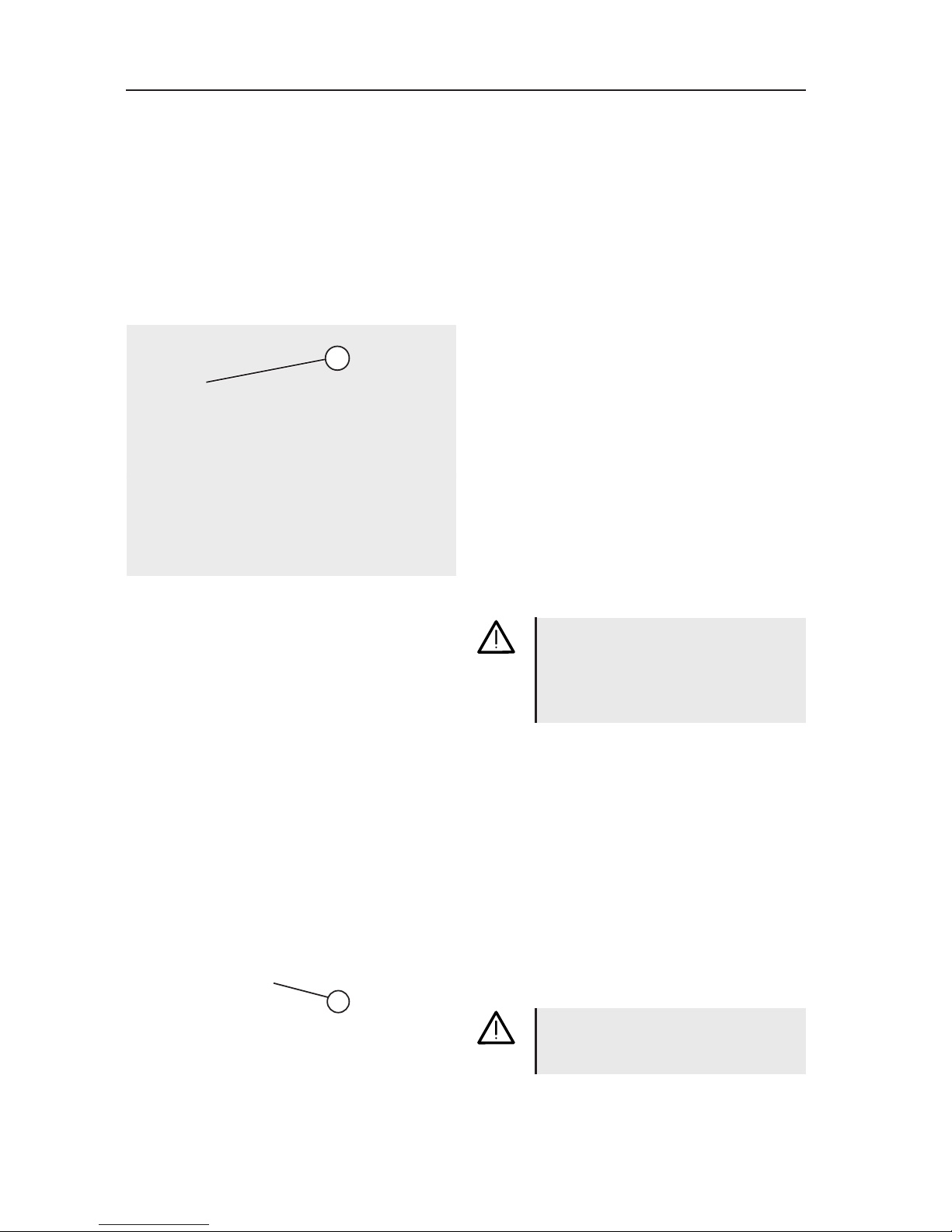
Name plate
Permit number
Vehicle ID number (FIN)
Permissible maximum weight
Permissible axle load, 1st axle
Permissible axle load, 2nd axle
Do not remove or change the name
plate.
The name plate is located in the lower front area on the right-hand side
wall.

03-11
b) The camper must be equipped with
hydraulic vibration dampers (shock
absorbers); naturally, your new HOBBY
camper is equipped with these.
c) The camper's tires may be no more than
six years old. They must be marked
at least with an L (= 120 km/h) for the
appropriate speed category.
d) The camper must be equipped with a
stabilising unit in accordance with ISO
11555-1 (standard in this HOBBY series
since 1997).
The overall mass of the camper may
not exceed the unladen mass of the
car.
5. Free interchangeability of base vehicle and
camper:
Different campers may be combined with
different base vehicles.
You are responsible for ensuring that the
preceding regulations are met if you plan to
drive at 100 km/h.
6. The correct drawbar load gives you more
safety:
Please refer to page 02-5 for the
recommended drawbar load.
3.11 Denition of mass
Denition of masses (weights) for
campers
The EG regulation 97/27/EG applies for calculating the masses (weights) and for the loading
which results from these calculations. The EG
regulations correspnd to a great extent to the
norm DIN EN 1645-2. The terms and basic
calculation elements used in this description are
explained in the following:
1. Gross vehicle weight rating (g.v.w.r.)
The indication of the gross vehicle weight rating
is taken directly from the HOBBY factory. These
weights were calculated as a result of lengthy
and detailed experiments; for safety reasons,
they may not be exceeded.

03-12
If you are not sure whether you have
overloaded the vehicle, weigh your
vehicle on a public vehicle scale.
Overloading can lead to malfunction
or even tire blowout!
This presents the danger of the
vehicle spinning out of control, which
endangers you as well as other dri-
vers and pedestrians.
2. Mass in running order
The mass in running order corrsponds to the
weight of the standard vehicle including all
standard equipment installed at the factory (e.g.
all-inclusive package) plus the basic equipment
(see Item 3).
3. Basic equipment
The basic equipment consists of all objects and
uids which are necessary for the safe and proper use of the vehicle. These include the masses
for gas, water and electrical supply (see Item
13.3 for a detailed specication).
4. Additional load
The additional load is the difference between
the "gross vehicle weight rating minus the mass
in running order". The remaining additional load
must be large enough to cover the weights of
possible additional equipment and personal
equipment.
5. Additional equipment
Additional equipment includes all items not
part of the standard equipment preinstalled in
the HOBBY factory or by the dealer. This also
includes installations by special request.
The mass in running order refers to the vehicle
as originally equipped by the dealer or factory.
This increases accordingly if special equipment
is installed.
Before the rst use, we recommend that you
weigh your vehicle on a calibrated vehicle scale.
In this manner, you can determine the maximum
permissible additional load for your vehicle.
04-1
Only use those tires designated in the registration documents. Other tire sizes may only be
used with the permission of the manufacturer.
• Check tires regularly to ensure that the tread
is worn down evenly; check tread depth;
check for external damages.
• Always use the same make and model of tires
(summer or winter tires).
• Drive carefully on new tires for a stretch of
approx. 100 km to enable them to develop a
full road grip.
2 31
Due to the type of construction, the
tires on campers with a tandem axle
may wear out more quickly.
4. Wheels, tires
4.1 Tires
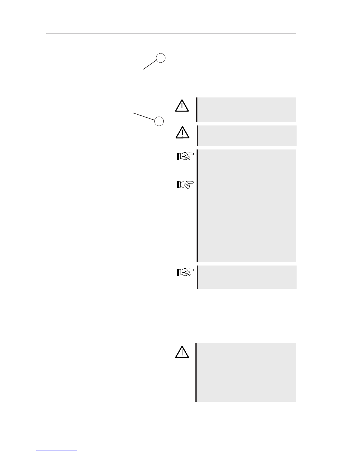
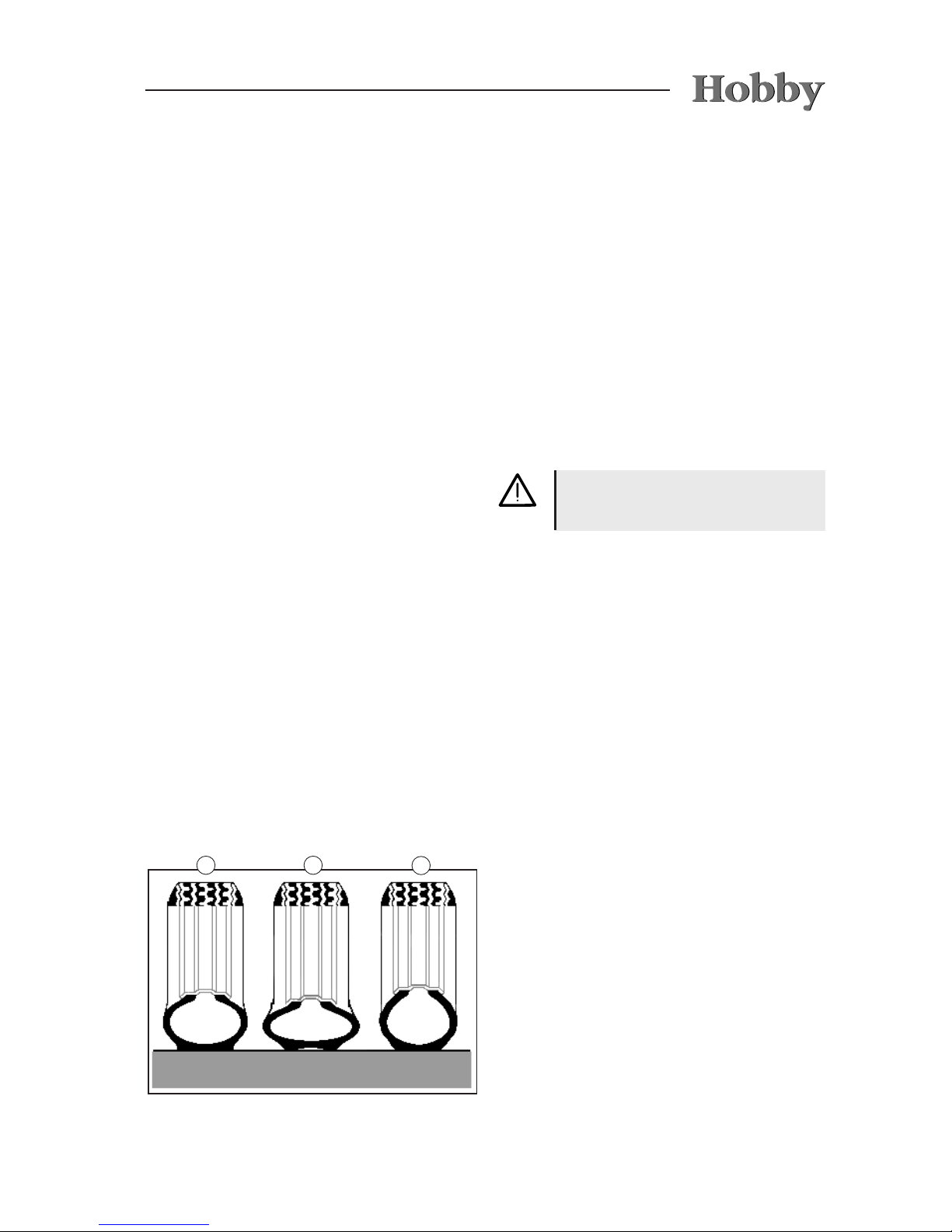
4.2 Tire pressure
Only one tire size is now entered in the motor
vehicle registration certicate, Parts I and II. This
must not necessarily correspond with the size
of the tires mounted on the vehicle. Should you
have any queries, please contact your dealer.
Rules for checking tire pressure:
• Check and x tire pressure every four weeks
(but at least every three months) and before
every drive.
• If driving on low tire pressure is unavoidable
(i.e., from the campsite to the nearest service
station) you should drive at a maximum
speed of 20 km/h.
• Tires must be checked when they are cold.
Rules for tire pressure:
- correct tire pressure
j
- tire pressure too low
k
- tire pressure too high
l
 Loading...