

Page 1
TM
© Copyright 1993, Hobbico, Inc.
• Comes 70% prebuilt, requiring very little sanding.
• Control surfaces are preshaped and ready for covering.
• Wing features balsa sheeting over foam core.
• Meets all requirements for Quickie 500 racing.
• Can be customized with
three different tail
configurations
Stock tail design
V-tail design
(optional)
Mid-tail design
(optional)
Page 2
C ongratulations upon purchasing your
new Viper RTC kit. The Viper RTC is
assembled with only the finest materials
and workmanship so you can enjoy the
fun of flying more quickly and easily than
ever before. We have completed 70% of
the assembly. All that needs to be done is
final assembly and covering - you can
customize. This airplane is a joy to fly and
promises hours of pure enjoyment. If
Quickie 500 racing is your goal., you will
find the Viper to be a very competitive
performer in the racing circles. For more
information on Quickie 500 racing,
contact the Academy of Model
Aeronautics at the address shown below.
Two decisions must be made before construction of this
airplane can begin.
1. What size engine will be used?
2. What style of tail will be used?
1. Engine Size:
If a .25 size engine is to be used for powering your Viper, no
additional reinforcement is required to the nose. You may
skip the steps with the checkered flag ( ). If a .40 size
engine is going to be used, complete the steps marked with
a checkered flag ( ).
2. Tail Configuration:
Conventional Tail:
This is a normal tail and all of the wood
required to build this version is included with this kit. This is
the easiest of the three versions to build and is highly
recommended for flyers/builders with limited building
experience.
Mid-Tail:
The mid-tail offers a very unique appearance to
the Viper as well as offering better elevator response. This is
due to the fact the stabilizer and elevator are out of the wing
slip stream. Although the mid-tail is not difficult to build, it
will require careful attention to insure the stabilizer and fin
are square.This can be either an aerobatic or racing
configuration and requires some additional 3/16" balsa to
complete.
V-Tail:
The V-tail version is slightly more difficult to build
than the other two versions. Extra care must be taken to
make sure the tail assembly is square, level and at zero
incidence. V-tail airplanes theoretically reduce drag
because there is only two control surfaces. This is primarily
a racing configuration and 3/16" balsa is required for
completion. This configuration is not recommended for
beginners. This also requires a radio that mixes V-tails or an
electronic mixer for elevator/rudder.
90-Day Limited Warranty
If you, as the original owner of this model, discover defects in
parts or workmanship within 90 days of purchase, Hobbico will
repair or replace it—at the option of our authorized U.S. repair
facility, Hobby Services— without charge. Our liability does not
include cost of shipping to us. However, Hobby Services will pay
shipping expenses to return your model to you.
You must provide proof of purchase, such as your original
purchase invoice or receipt, for your model’s warranty to be
honored.
This warranty does not apply to damage or defects caused by
misuse or improper assembly, service or shipment. Modifications,
alterations or repair by anyone other than Hobby Services voids
this warranty. We are sorry, but we cannot be responsible for crash
damage and/or resulting loss of kits, engines, accessories, etc.
Repair Service
Your Viper must be returned directly to Hobby Services for
warranty work. The address is:
Hobby Services
Attn: Service Department
1610 Interstate Drive
Champaign, IL 61821-1067
Phone: (217) 398-0007
Hours: 9:00-5:00 CST Mon. thru Fri.
Please follow the instructions below when returning your model.
This will help our experienced technicians to repair and return it as
quickly as possible.
1. ALWAYS return your entire kit.
2. Include a list of all items returned and a THOROUGH, written
explanation of the problem and service needed. If you expect the
repair to be covered under warranty, also include your proof of
purchase.
3. Include your full return address and a phone number where you
can be reached during the day.
If your model is past the 90-day warranty period or is excluded
from warranty coverage, you can still receive repair service
through Hobby Services at a nominal cost. Repair charges and
postage may be prepaid or billed COD. Additional postage charges
will be applied for non-warranty returns. All repairs shipped
outside the United States must be prepaid in U.S. funds only.
All pictures, descriptions and specifications found in this
instruction manual and on the product package are subject to
change without notice. Hobbico maintains no responsibility for
inadvertent errors.
Academy of Model Aeronautics
5151 E. Memorial Drive
Muncie, IN. 47302
Tel. (317) 289-4236
JOIN THE AMA
About this manual:
- 2 -
Page 3
Other items you’ll need:
Glues
Choose any 5- or 6-minute epoxy, such as Hobbico Bullet, which has been formulated
especially for R/C model building. Epoxies offer a strong bond and a variety of curing
times suited for every step of assembly. You’ll also need an instant-setting CA
(cyanoacrylate), a thicker CA+, and a 30-minute epoxy, plus rubbing alcohol for easy
epoxy cleanup.
Hardware
Tools and accessories required for assembly include
a hobby knife; flat tip screwdriver; file; needle nose
pliers; drill bits; ruler; and 3 feet of medium fuel
tubing.
Model Engine
Power your Viper with any high-quality, .25-size
model engine. The O.S. ..25 FP, SuperTigre G-34 and
Irvine .25 RC are just a few examples. Look for
features such as easy break-in, easy starting, efficient
carburetion and low maintenance. Check the
manufacturer’s recommendations for propellers to
use with your engine. For Quickie 500 racing you will
want to choose a high performance, .40 size engine.
Radio Equipment
To let you send the commands that control your Viper’s
“flight path,” you’ll need a 4-channel aircraft radio system
with four standard servos. Many 4-channel radios include
just three servos. You may need to purchase the fourth
separately. The servos and radio receiver will be mounted
on-board your model and need to be cushioned from jolts
and vibration. One-quarter inch thick foam rubber sheets
are available for this purpose.
Getting Ready for Flight
Your Hobbico Viper is ready for takeoff in as little as 15-20 hours. Your
hobby dealer can help you decide what accessories you’ll need for flight.
You will need glow fuel with a 10-15% nitro blend to keep your engine
performing at its peak...and your Viper will have the power to perform the
impressive aerobatic maneuvers.
Other General Items Required
Masking Tape
Fine Line Felt Tip Pen
A Wooden Match
Balsa Filler
Covering Material
Sealing Iron
1/4"-20 Tap
Engine Mount
Hex Wrench for #6-32 Bolt
3M "77" Spray Adhesive
90Þ Triangle
Sand Paper (220 grit)
Drill and Drill Bits:
1/16", 1/8", 9/64", 5/32", #7
or 3/16", 1/4"
Additional Items Required for Optional Quickie Racer, V-Tail or Mid Tail
1 sq. Yard 2oz. Fiberglass
3/16 Hard Balsa (V-Tail and Mid Tail)
Wire and Tube Pushrod
Cable Pushrod (for throttle)
6 oz. Hayes Fuel Tank
Candle Wax
45 Minute Epoxy
- 3 -
Page 4
FUSELAGE PREPARATION
Marking firewall for engine mount
1. With a straight edge, draw lines from corner to corner
on the firewall. This will help you position the engine mount.
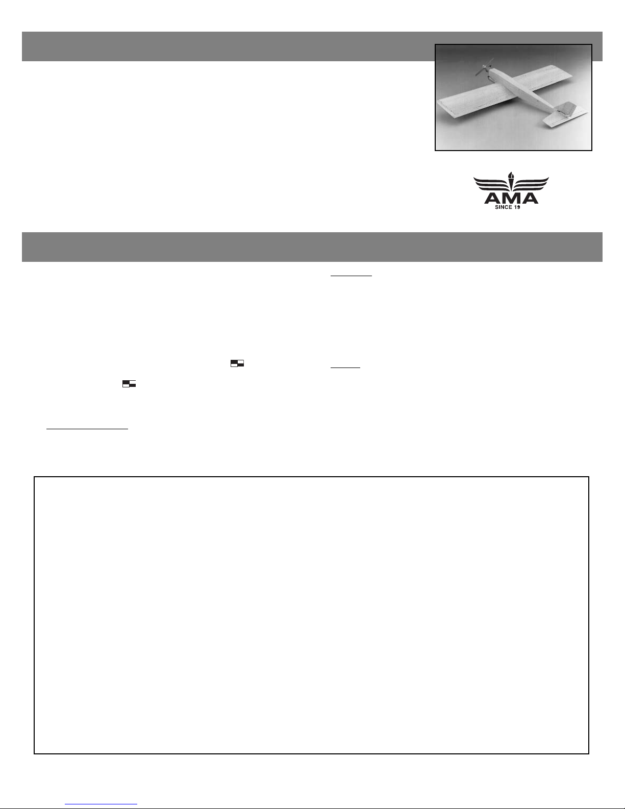
Drilling holes for engine mount
2. Center the engine mount on the firewall using the lines
as a reference. Mark and drill 5/32" (4mm) holes according to
the motor mount you plan to use.
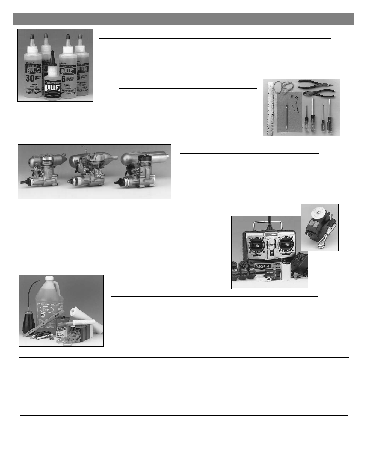
Installation of blind nuts
3. Using a file or a Moto-Tool™, remove the triangle stock
around the holes drilled through the firewall. This creates a flat
surface to mount the blind nuts against. Install #6-32 blind
nuts into the holes and apply thick CA to secure them in place.
Hardening blind nut holes
4. Apply thin CA to the outside of the holes to harden the
firewall around the blind nuts.
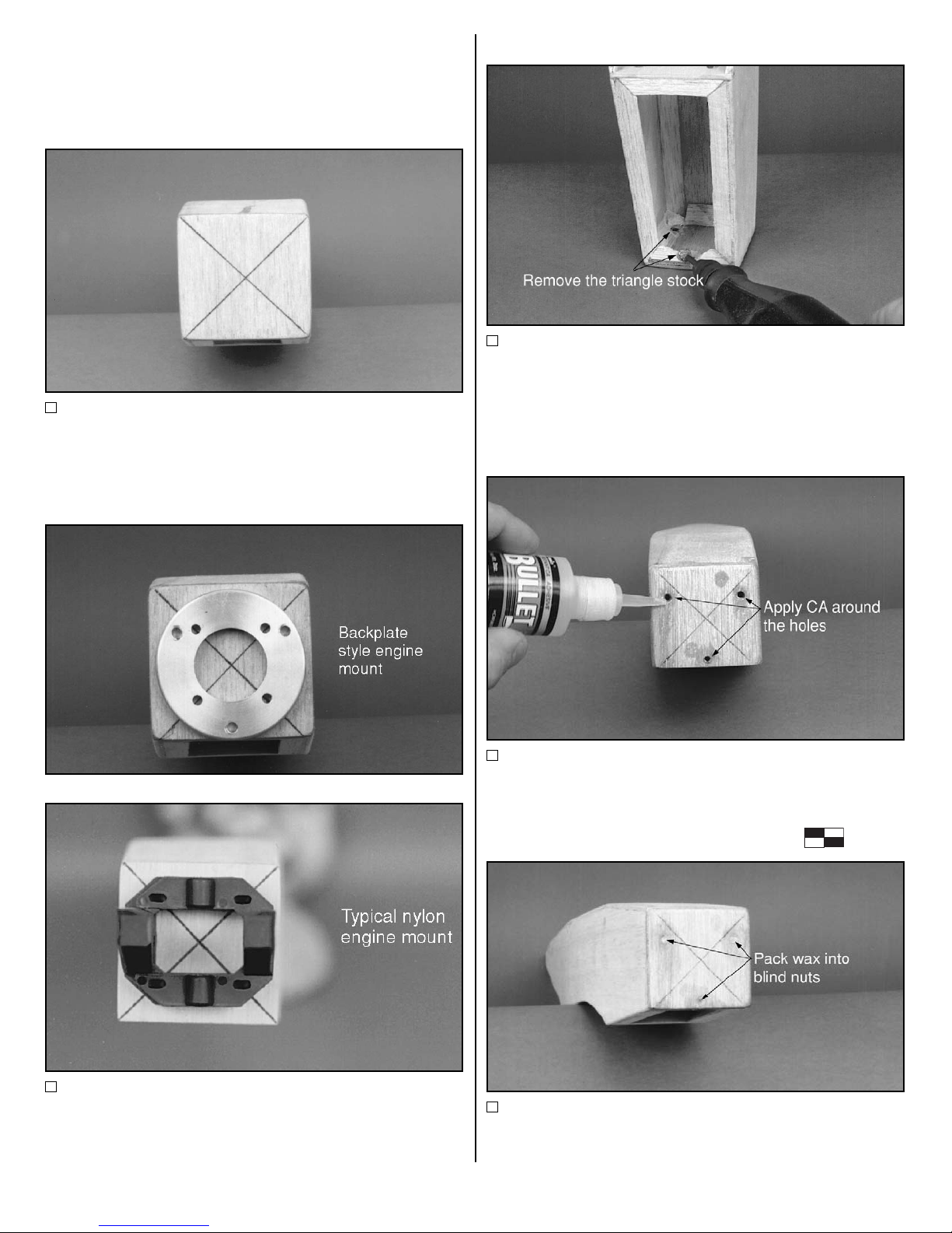
Protecting blind nut threads
5. Pack wax into each of the blind nuts to protect the
threads from being clogged by epoxy.
- 4 -
Page 5
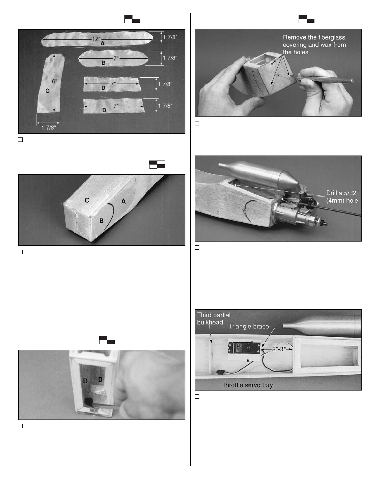
Cutting fiberglass cloth
6. Cut (5) pieces of 2 oz. fiberglass cloth as shown. Mark
the center of pieces A, B, and D.
Installing the fiberglass cloth
7. Apply a very light coat of 3M "77" spray adhesive to the
nose of the fuselage. Place the center of piece "A", cut in the
previous step, at the center of the firewall and wrap the
remainder around the left and right sides of the fuselage. Wrap
piece "C" starting at the bottom of the firewall up over the top of
the fuselage. Wrap piece "B" starting at the center of the
firewall over pieces A and C and around the sides of the
fuselage. Coat the fiberglass cloth with 45 minute epoxy and
remove all excess epoxy with a squeegee.
Fuel proofing the
fuel compartment
8. Install piece "D" of the fiberglass cloth on the inside,
wrapping from one side over the firewall to the other. Install
the other piece "D" from the bottom of the firewall to the top
of the fuselage. Completely coat the entire fuel tank
compartment, making sure all of the fiberglass is saturated
and the fuel compartment is fuel proof.
Opening the blind nuts
9. Using a hobby knife, remove the fiberglass covering the
bolt holes. Pick the wax out of each of the blind nuts.
Drilling hole for throttle rod tube
10. Using a 5/32" (4mm) drill bit, drill a hole through the
firewall directly behind the throttle arm. This will be the hole
for the throttle rod tube. Drill another hole through the second
bulkhead and in the most direct path to the throttle servo.
Make sure it does not interfere with the wing saddle. Note: A
long drill bit is shown but not nexessary.
Installation of throttle servo tray
11. Using a file, enlarge the throttle servo tray hole to
accommodate the servo being used. Then, with thick CA,
install the throttle servo tray as shown. Make sure that
enough room is left under the servo tray to accommodate the
throttle servo you'll use. Also make sure the throttle servo will
not interfere with the aileron servo. Install the servo tray 2" to
3" from the second bulkhead. Locate the triangle brace and
install it under the front portion of the servo tray using thin
CA. Mount the throttle servo according to the manufacturer's
recommendations.
- 5 -
Page 6
Installation of throttle rod
12. Roughen the entire throttle rod tube using sandpaper.
Slide the tube through the hole in the firewall and the first
bulkhead. Slide the rod into the tube and direct the rod
straight to the servo arm with as little bending as possible.
Apply epoxy to the tube where it goes through the firewall
and the first bulkhead. Also attach the tube securely to the
side of the fuselage. Thread a clevis onto the throttle
pushrod. Slide the pushrod into the tube and out past the
servo. Mark the pushrod where the pushrod crosses the
outside hole of the throttle servo arm. Place a "Z" bend at this
mark. Connect the "Z" bend to the throttle servo arm. Adjust
the pushrod using the clevis. Note: It may be necessary to
replace the pushrod with a cable in some engine positioning
situations.
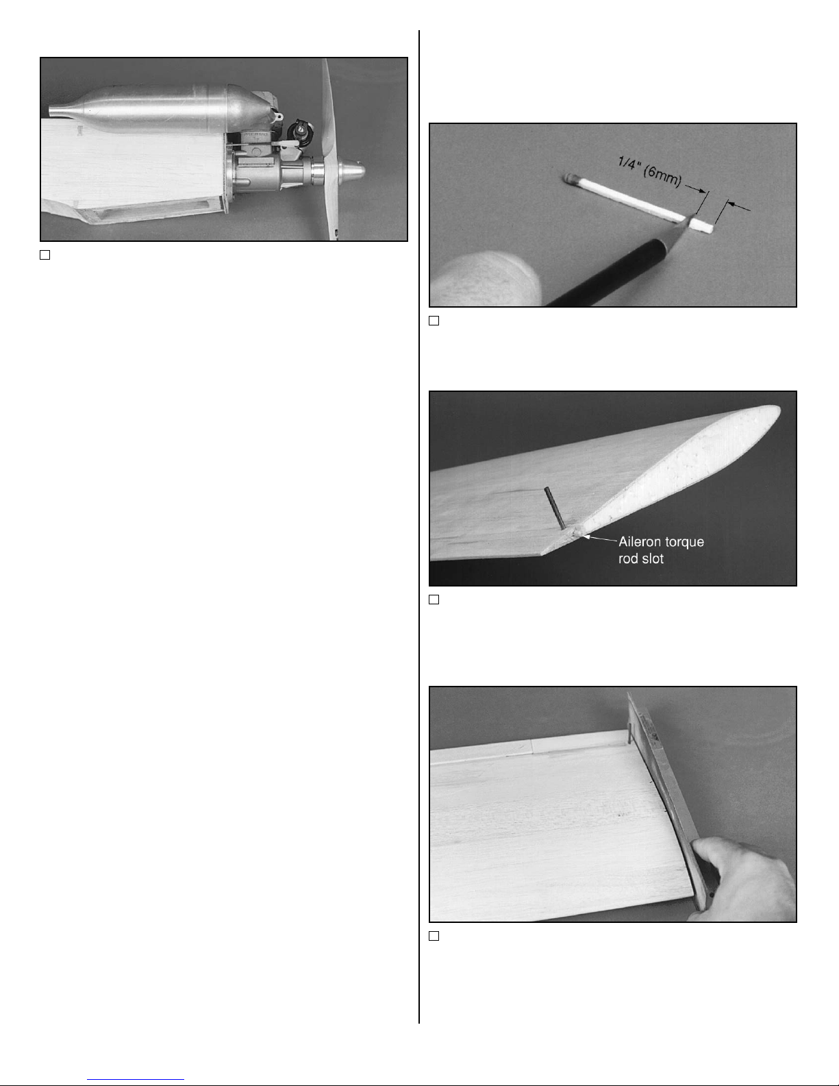
ASSEMBLY OF WING
Making an alignment peg
1. Cut about 1/4" (6mm) off the end of a wooden match or
similar piece of wood.
Installation of alignment peg
2. Using thick CA, glue the piece of match into the hole in
the aileron torque rod slot in the trailing edge of one of the
wing panels. This will serve as an alignment peg.
Trial fitting wing halves
3. Position the two wing halves together and check their fit.
Adjust the angle of root center section using a sanding block.
This should be done with the wing on a flat surface and one
of the wing panels blocked up to the proper dihedral angle. It
is 5/8" (16mm) for Quickie 500 racing or aerobatics and 1"
(25mm) for beginners.
- 6 -
Page 7
Setting wing dihedral
4. Use a piece of 5/8" (16mm) or 1" (25mm) scrap balsa to
block up one wing panel. This will account for the dihedral
required for the wing. If this is your first low wing airplane,
increase the dihedral from 5/8" (16mm) to 1" (25mm). Place
a piece of wax paper on your building surface to prevent the
wing from sticking to the surface.
Applying epoxy to wing panel
5. Using 30- or 45-minute epoxy, apply a liberal amount of
epoxy to each wing panel as shown, making sure that epoxy
is applied to the balsa sheeting as well as the foam core.
Wing panel assembly
6. Assemble the wing panels together and remove any
epoxy that may have squeezed out. Block up the trailing
edge using a piece of 5/8" (16mm) balsa. Masking tape
should be used to hold the panels tightly together until the
epoxy has fully cured. Note: Wax paper was used to prevent
the wing from sticking to the building surface.
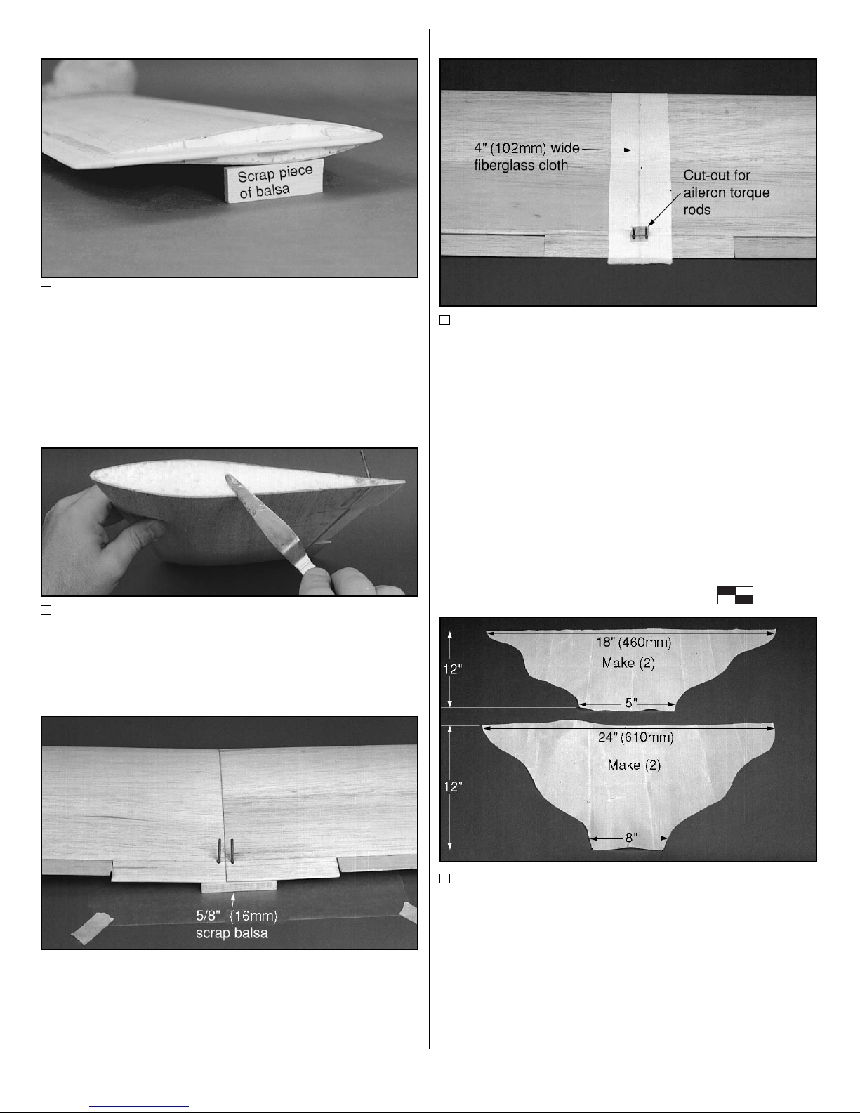
Fiberglassing the wing joint
7. Apply 30- or 45-minute epoxy and thoroughly saturate
the fiberglass cloth. Once saturated, squeegee off as much
epoxy as possible. Remember, this is excess weight. Once
the epoxy has cured, repeat this procedure for the top of the
wing. Hobbylite filler should be used to smooth the transition
from the fiberglass to the wood skin. Make sure a cut out is
made to fit around the aileron torque rods and that no epoxy
is allowed into the torque rod openings.
Cutting the fiberglass cloth
8. Cut 2 oz. fiberglass cloth into the panel dimensions
shown above. Cut two of each panel.
- 7 -
Page 8
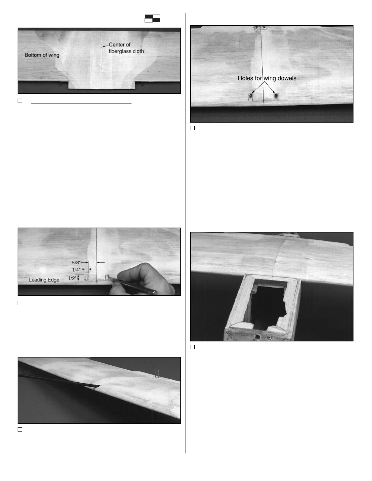
Applying the fiberglass cloth
9. Start with the bottom of the wing first. Mark the center of
the fiberglass panels cut in the previous step. Apply the 24"
(610mm) wide piece first and then the 18" (460mm) wide
piece over the top of it, making sure that the center marks
line up on the center section of the wing. Apply 30- or 45minute epoxy and thoroughly saturate the fiberglass cloth.
Once saturated, squeegee off as much epoxy as possible.
Remember, this is excess weight. Once the epoxy has cured,
repeat this procedure for the top of the wing. Hobbylite filler
should be used to smooth the transition from the fiberglass to
the wood skin. Note: The fiberglass goes right over the
landing gear blocks. Once the epoxy cures, use a hobby
knife to remove the fiberglass from the wire slots.
Cutting holes for hold down dowels
10. Using the photo as a reference, draw 2 boxes as
shown and then 2 ovals inside the boxes. Using a hobby
knife, cut through the fiberglass and balsa and remove only
the oval portions drawn.
Drill holes for hold down dowels
11. With a 1/4" (6mm) drill bit, drill holes into the foam core
at approximately the angle shown, 3" deep. Note: A long drill
bit is shown, but is not required.
Trimming the hold down dowels
12. Cut (2) wing hold down dowels to 3-1/2" (89mm).
Round one end of each of the dowels. Insert the round end of
each of the dowels into the holes in the wing. Trial fit the wing
onto the fuselage, checking the fit with the first bulkhead. If
necessary, adjust the bulkhead grooves or oblong the holes
in the wing to achieve a good, snug fit between the bulkhead
and the dowels. If necessary, adjust the wing saddle until the
wing fits perfectly to the fuselage.
Installation of hold down dowels
13. Apply a generous amount of 30-minute epoxy both to
the wing hold down dowels and to the holes in the wing for
the dowels. Insert the dowels, with the flat end out, into the
wing. Leave 5/8" (16mm) of the dowels protruding past the
leading edge of the wing. Install the wing onto the fuselage
and hold the dowels snug against the bulkhead until the
epoxy cures. Make sure the 30-minute epoxy does not
contact the fuselage.
- 8 -
Page 9

Marking the aileron servo hole
14. Using the aileron servo as a reference, mark and cut a
hole in the center section of the wing, starting the hole 3-3/4"
(95mm) to 4" (102mm) from the leading edge of the wing.
Make sure that the position chosen does not allow the aileron
servo to interfere with the throttle servo.
Installing the aileron servo tray
15. Locate the aileron servo tray and adjust the size of the
hole to correspond with the hole already cut in the wing.
Using 6-minute epoxy, glue the aileron servo tray to the wing.
Installation of aileron servo and rods
16. Install the servo and connect the torque rods using the
(2) 8" (203mm) pushrods, (2) clevises and (2) aileron torque
rod connectors. "Z" bends should be used on the pushrod
ends that connect to the servo. Note: The small hole in front
of the servo tray is for the aileron servo wire.
Drilling for the wing hold down bolts
17. Install the wing onto the fuselage as shown. Check to
make sure that the distance between the wing tip trailing
edge and the tail of the fuselage are the same for each side.
Mark the outside of the fuselage and the inside of the wing
hold down block on each side. Place a mark halfway
between these marks and 1/2" (13mm) ahead of the trailing
edge. Drill holes through the wing and hold down blocks
perpendicular to the wing at these marks using a #7 or 3/16"
(5mm) drill bit. Remove the wing and enlarge the holes in the
wing with a 1/4" (6mm) drill.
Tapping the holes
18. Using a 1/4"-20 tap, carefully tap the holes in the hold
down blocks. Once tapped, reinforce the hold down blocks
using thin CA along the joint and the triangle stock.
- 9 -
Page 10

INSTALLATION OF
CONVENTIONAL TAIL
SURFACES
Important: Make sure this is the tail configuration you have
chosen to use. If it is not, turn to page 11 for mid-tail or
page 13 for V-tail.
Marking the horizontal stabilizer
1. Mark the exact center of the stabilizer and draw a center
line perpendicular to the trailing edge on the top and bottom of
the stabilizer.
Installation of the horizontal stabilizer
2. Check the fit if the stabilizer in the stabilizer saddle. Sand
the saddle to make a perfect fit. Apply 30-minute epoxy to the
stabilizer saddle and to the bottom of the stabilizer itself.
Install the stabilizer onto the fuselage and check to insure that
the distance between the trailing edge of the wing tip and the
trailing edge of the stabilizer are the same. Then, sighting
from the rear, check to make sure the stabilizer is parallel with
the wing. Set the stabilizer assembly aside to cure.
Installation of vertical stabilizer
3. Using a 90Þ triangle, install the vertical stabilizer using
30 minute epoxy. Make sure the fin lines up perfectly with the
center line of the fuselage.
Bracing the vertical stabilizer
4. Locate the (4) pieces of 1/4" (6mm) triangle stock. Sand
the front and back to achieve a pointed appearance on each
end. Using thick CA glue, install the (2) longer triangle stock
pieces on top of the stabilizer and up against the vertical
stabilizer. Do not use the 6" (150mm) piece of 1/4" (6mm)
triangle stock for this step.
Bracing the horizontal stabilizer
5. Install the (2) shorter triangle stock pieces underneath
the stabilizer and against the fuselage. Skip to page 15 if you
are assembling the conventional tail.
- 10 -
Page 11

Relocating the antenna tube
6. Drill a 1/8" (3mm) hole and install the antenna tube and
secure using thick CA. Trim the antenna tube flush to the
fuselage.
MID TAIL DESIGN
(Follow this section for mid-tail only)
Trim the horizontal stabilizer
1. Carefully remove 1/2" (13mm) of balsa from the trailing
edge of the existing stabilizer. Using the elevator template on
page 22 as a reference, slot the trailing edge of the stabilizer for
the hinges with a #11 knife blade. This will allow using CA style
hinges. CA hinges are recommended for the mid-tail design.
Cutting a new vertical stabilizer and
rudder
2. Cut out the new vertical stabilizer (3/16" (5mm) balsa is
not provided) using the template provided on page 21. Cut a
slot from the center of the leading edge of the stabilizer 3/16"
(5mm) wide and 1-3/4" (45mm) deep, to form the interlock for
the vertical stabilizer. Round the leading edge of the vertical
stabilizer. Slot the stabilizers for hinges, using a #11 knife
blade, according to the template.
Joining the horizontal and vertical
stabilizer
3. Install the horizontal stabilizer into the vertical stabilizer.
Using a 90Þ triangle to square the fins, apply thin CA glue to
- 11 -
Page 12

the joint. Once the fins are tacked into place, go over the joint
again with thick CA glue. Cut the 1/4" (6mm) triangle stock
provided into (4) pieces 2-3/4" (70mm) long. Install the
triangle stock along each joint to reinforce the joints. Bevel
the front and rear of the triangle stock to eliminate drag.
Remove the plywood reinforcement
4. Using a razor saw, remove 3/16" (5mm) of the plywood
reinforcement from the aft end of the fuselage to make room
for the vertical stabilizer.
Installation of the fin assembly
5. Apply 30-minute epoxy to the vertical stabilizer and to
the slot in the fuselage, also making sure to apply glue to the
tail skid mounting plate. Install the fin assembly into the
fuselage and make sure the stabilizer is square with the
wing. Note: You may find it easier to cover the entire fin
assembly with MonoKote®, except the bottom portion, before
installing it onto the fuselage. Use scrap balsa about 3/16"
(5mm) thick to fill the old stabilizer saddle of the fuselage.
Drill a hole in the top left scrap piece for installation of the
elevator pushrod.
Installing the rudder pushrod
6. Drill a hole and install the rudder pushrod according to
the recommendation of the manufacturer. Great Planes™
Rod-in-Tube pushrods are recommended.
Relocating the antenna tube
7. Drill a 1/8" (3mm) hole and install the antenna tube and
secure using thick CA. Trim the antenna tube flush to the
fuselage.
Making the elevators
8. Cut out (2) mid-tail elevators using the template
provided on page 22. Use a #11 knife blade to slot the
elevator for CA type hinges in the location shown. Drill a
3/32" (2.4mm) hole according to the template for the
elevator for the interlink. Recess the elevator to receive the
interlink and bevel the leading edge of the elevator. Use 30minute epoxy to glue the interlink into the elevator halves.
Make sure the elevators are perfectly level and straight
across. Drill holes and attach the control horn according to
the portions indicated on the template for the rudder and the
elevator.
- 12 -
Page 13

Attachment of pushrods
9. Attach the pushrods to the controls according to the
manufacturer's recommendations. Use the rudder horn with (2)
holes and a full length horn for the elevator shown above.
Connecting the servos to the
pushrods
10. Refer to page 15 steps 1, 2, and 3 to install the servo
tray. With the elevator and rudder perfectly level and straight,
mark the point where the pushrod passes over the servo arm
about 1/2" (13mm) from the center. Make Z-bends at the
marks and install the servo arms onto the Z-bends.
11. Do not permanently install the control surfaces until
after the Viper is covered.
V-TAIL DESIGN
(Follow this section for V-tail only)
Cutting new stabilizers
1. From hard balsa, cut (2) stabilizers, (4) triangle braces, and
(2) elevators using the templates provided on page 22 and 23.
Slot the stabilizers and elevators using a #11 knife blade, for
CA style hinges. Use the template for hinge position.
Attach the triangle braces to the
stabilizers
2. Using thick CA glue, tack glue one of the triangle braces to
the bottom of one of the stabilizers at the trailing edge, and
another brace close to the leading edge. Set the assembly on
a flat surface and sand the root of the stabilizer perpendicular
to the surface. Repeat this procedure for the other stabilizer.
This will make a perfect joint between the two halves.
Glue the stabilizers together
3. Trial fit the two stabilizers together and make sure the
trailing edge is straight. Once the trailing edge is straight, glue
the two stabilizers together.
- 13 -
Page 14

Reinforce the stabilizer joint
4. Break the four triangle braces from the stabilizers and
remove any excess CA with 220 sand paper. Sand the
pointed joint at the bottom of the two stabilizers. Reinforce the
joint on both sides using 1" (25mm) wide 6 oz. fiberglass or
carbon fiber (not included).
Trim the tail of the fuselage
5. Lay the template provided over the tail of the fuselage
and trim the fuselage accordingly.
Checking incidence of the tail
6. Check the incidence of the stabilizer on the newly cut
cradle. This should be done with the top of the fuselage as a
reference and perfectly level. The top of the fuselage is the
thrust line. Use of a simple line level is recommended.
Attach the stabilizer
7. Once the incidence of the stabilizer is correct, check to
make sure the distance from the trailing edge of the wing tip to
the trailing edge of the stabilizer is exactly the same on each
side. Check to make sure it is square to the wing and tack glue
the stabilizer into place using thin CA glue. Re-check the
measurements and if it hasn't moved, permanently glue the
stabilizer in place with 30 minute epoxy. Let stand until the
epoxy cures.
Install the pushrod braces
8. Install a piece of scrap balsa over the top of the V-tail as
shown. Drill (2) holes and mount the pushrods according to
the recommendations of the manufacturer of the pushrod.
Great Planes™ Rod-in-Tube pushrods are recommended. Cut
out and drill holes in the ruddervators according to the
template on page 23 and mount the control horns.
Connecting the ruddervator servos
9. With the ruddervators level, mark the point where the
pushrods pass over the servo arms about 1/2" (13mm) from
the center. Make Z-bends at the marks and install the control
arms onto the Z-bends. Attach the pushrods to the servos.
Install the antenna tube
10. The antenna tube should be routed out under the V-tail
as shown.
11. Do not permanently install the control surfaces until the
model is covered.
- 14 -
Page 15

PUSHROD INSTALLATION
Trimming the servo tray
1. Enlarge the holes in the elevator and rudder servo tray to
fit the servo being used. Mount the servos in the servo tray
and set the servo tray into place, with the servos resting on the
top of the fuselage as shown. With a pen, place a mark on
each side of the fuselage using the tray as a guide. Note: In
most .25-.40 size engine applications, it is best to mount the
servos aft of the fourth bulkhead. To do so, use the template
on page 24 to trim the servo tray to fit. If you intend to use a
.19 size engine, or a very light engine, simply mount the servo
tray ahead of the bulkhead. It will be necessary to lengthen the
pushrods by about 2-1/2" (64mm) over the dimensions shown
on page 16.
Installation of the servo tray
2. Cut the 6" piece of 1/4" (6mm) triangle into
(2) 3" (76mm) pieces. Using the marks as a guide, glue (2)
pieces of 1/4" (6mm) triangle stock 3" (76mm) long into place
on the inside of the fuselage. This will insure an 1/8" (3mm)
gap between the servos and the top of the fuselage. Using
thick CA glue, install the servo tray onto the triangle stock.
Trimming the control horns
3. Cut both of the control horns as shown. The smaller
version will be the elevator control horn and the one with 2
holes will be the rudder control horn. Note: This is for the
conventional tail configuration. For the mid tail, cut the rudder
horn as shown, but do not cut the elevator control horn. Do not
cut the control horns for the V-tail configuration. Note: For high
performance .40 size applications we recommend the use of
Great Planes™ Rod-in-Tube type pushrods for elevator
and rudder.
Drilling the dowel rod
4. Drill 1/16" (1.6mm) holes 3/4" (19mm) from each end of
both the wooden pushrods.
Making the V-groove
5. Make a small groove on each end of the pushrods from
the 1/16" hole to the end.
- 15 -
Page 16

Installation of rods
6.Using thick CA, secure one of the unthreaded rods onto
one end of the pushrod and the threaded rod on the other side.
Installation of heat shrink tubing
7. Cut the black heat shrink tubing into 4 equal pieces and
install on over each of the pushrod joints. Shrink the tubing with
either a match or a heat gun.
Assemble the pushrods for aft
mounted tray
8. Bend the pushrods as shown. Note: Trial fit before
making "Z" bends and cutting off extra wire.
Installation of elevator control horn
9. Set the elevator control horn in place, centered on the
hole in back of the fuselage, and mark the hole locations with a
pen. Drill 5/64" (2mm) holes at the marks. Install the control
horn using (2) 2mm screws and the control horn backing plate.
Attach the clevis to the control horn. It may be necessary to
enlarge the opening at the rear of the fuselage to allow free
movement of the pushrod. If necessary, enlarge the hole using
a round file.
Connecting the elevator pushrod
10. With the elevator in the neutral position and the servo
arm 90Þ to the servo, place a mark on the pushrod at the point
it intersects the outside hole on the servo arm. This should be
about 1/2" (13mm) from the center of the servo arm. Make a
"Z" bend at the mark and install it onto the servo arm.
Installation of rudder control horn
11. Hold the control horn (with 2 holes on it) in place as low
on the rudder as possible. With the 2 holes aligned over the
hinge line, mark the screw holes on the rudder. Drill (2) 5/64"
(2mm) holes at these marks and install the control horn using
(2) 2mm screws and the control horn backing plate.
- 16 -
Page 17

Slot for rudder pushrod
8. Make a slot 1" (25mm) long starting 1/4" (6mm) behind
the leading edge of the stabilizer. This slot should go through
the triangle stock and the stabilizer.
Installation of rudder pushrod
9. From the inside of the fuselage, insert the threaded end
of the rudder pushrod through the slot in the rear stabilizer.
Thread a clevis onto the pushrod and attach it to the rudder
control horn.
Adjustment of rudder control horn
10. With the rudder in the neutral position and the rudder
servo arm 90Þ to the servo, place a mark on the pushrod at
the point it intersects the outside hole of the servo arm. This
should be about 1/2" (13mm) from the center of the servo arm.
Make a "Z" bend at this mark and install onto the servo arm.
Make sure the elevator and rudder pushrods do not contact
each other. If so, bend the rudder pushrod slightly to
avoid contact.
FINISHING THE FUSELAGE
Straightening the fuselage
1. In some cases the sides of the fuselage bow in slightly. If
this happens, simply install a couple of scrap pieces of balsa
to return the fuselage sides to their original shape.
Relocating the antenna exit hole
2. On the conventional and mid-tail configurations, it is
necessary to relocate the exit for the antenna tube. To do this
drill a 9/64" (3mm) hole under the stabilizer about 3" (76mm)
from the end of the fuselage. Glue the tube in place using thick
CA. A pushrod may be used to hold the exit straight while
gluing.
Installation of lower sheeting
3. Install the lower sheeting using thick CA glue and sand
the sheeting flush with the fuselage sides. Then round the
corners to a 1/4" (6mm) radius.
- 17 -
Page 18

Inspection hole
4. Use a round file or Moto-Tool™ to cut an inspection hole
in the bottom sheeting of the fuselage. Make sure that the
corners are rounded with at least a 1/4" (6mm) radius. This
hole should be large enough to remove a servo if necessary.
Cover the hole with clear tape or clear MonoKote® covering
after the entire model is covered.
Installation of tail skid
5. Drill an 3/32" (2mm) hole for the tail skid 2-1/2" (64mm)
from the end of the fuselage. Using the skid as a guide, locate
the position for the front hole. After covering is complete, glue
the skid in place using thick CA or epoxy.
Removing fiberglass over the gear
blocks
6. Using a #11 knife blade, trim the fiberglass that is
covering the landing gear slot. Use a piece of 220 grit
sandpaper to trim the edges.
Installation of landing gear
7. Install the landing gear into the landing gear block. If the
fit is too snug, run a 5/32" (4.0mm) drill bit into the hole. Make
sure you do not drill through the top of the wing. Place the
landing gear straps over the wire and mark the holes with a
pen. Drill 1/16" (1.6mm) holes at the marks and secure the
straps in place. Install a wheel and then a wheel collar to
secure. Repeat this procedure for the other side.
Assemble the fuel tank
8. Assemble the fuel tank as shown. The fuel tank supplied
is about 4 oz., which is perfect for .19 to .25 engines. If you
plan to race the Viper, you will want to replace this with a
Hayes 6 oz. fuel tank.
- 18 -
Page 19

Drill the fuel line exit hole
9. Cut a 1/2" (13mm) round hole 1/2" (13mm) back from the
front of the fuselage. This will serve as the exit for the fuel
lines. This may seem slightly unconventional, but the
advantage is, it does not weaken the firewall at all.
Trim the fuselage for the fuel tank
10. With a hobby knife, trim the triangle stock flush with the
number two bulkhead. This will make installation of the fuel
tank easier. Thoroughly coat the inside of the fuel tank
compartment with 30-minute epoxy to fuelproof the wood.
Install the fuel tank
11. Route the fuel lines through the hole and install the fuel
tank as shown. Make sure fuel lines are not pinched against
the firewall. Pack 1/4" (6mm) foam around the fuel tank to
isolate the fuel tank from vibration.
Installation of fuel tank
compartment hatch
12 Using thick CA, install the fuel tank compartment hatch.
Sand the edges flush with the fuselage sides and then radius
to a 1/4" (6mm).
Finishing the model
Applying the covering
Remove all of the fittings, pushrods and control horns. This
will make covering much easier and neater. It will take about 2
rolls of MonoKote® to cover the Viper. Use your imagination
and you can create a very attractive airplane. Once the Viper
is covered, re-install all of the fittings. Cover the servo access
hole and the fuel tank compartment hole with clear tape or
clear MonoKote®. Note: Check to insure there is adquate
clearance, about 1/32" (1mm) on each end of the aileron to
prevent binding.
Wing bolt reinforcement plate
Place the wing bolt reinforcement plate over the bolt holes
on the bottom of the wing. Center it on the center line of the
wing. Mark the location and remove the covering from
underneath. Using thick CA, glue the plate in place. Re-drill
the holes from the top of the wing using a 1/4" (6mm) drill.
Apply covering to the plate.
- 19 -
Page 20

Wing saddle seal
Use of bathtub silicone sealer is recommended for sealing
the wing to fuselage joint. This is an excellent method, used by
many experts because it results in a permanent and nearly
perfect wing saddle joint. Briefly, the technique is as follows:
1. Cover the top of the wing center section with waxed paper
or plastic kitchen wrap. Pull out all wrinkles and tape it to the
wing. 2. Squeeze out a bead of silicone sealer onto the wing
saddle area of the fuselage. 3. Lay the wing in the saddle and
push down gently. The excess silicone sealer will squeeze out.
4. Allow to dry without disturbing for at least 24 hours. 5.
Remove the tape; then remove the wing from the saddle
(leaving the waxed paper or plastic wrap in place)
6. Gently pull the waxed paper or plastic wrap away from the
sealer. 7. Using a new single-edge razor blade, trim the
sealer flush with the wing fillets, and along the inside of the
fuselage.
Control surface installation
Apply petroleum jelly to the moving portion of each of the
hinges from one of the ailerons. Apply a small amount of
epoxy to one side of the hinge and in the hinge slot on the
aileron. Repeat this procedure for the other two hinges. Set
aside to cure. Once cured, repeat this procedure on the wing,
using a small stich to pack the aileron torque rod hole with
epoxy. Then install the aileron onto the wing. Make sure no
epoxy remains on the moving portion of the hinge. If it does,
remove the epoxy quickly with alcohol. Repeat this procedure
for the other aileron, rudder and elevator.
Radio installation
Install the receiver, battery and switch according to the
manufacturer's recommendations. Protect the equipment with
1/4" (6mm) foam rubber. Move the battery and receiver back
and forth until the proper center of gravity is achieved. Route
the antenna through the antenna tube. Use scrap balsa and
foam to secure the receiver and battery pack.
Balancing the model laterally
With the wing attached to the fuselage and level, lift the
model by the engine propeller shaft and at the centerline of the
fin. Do this several times. Notice if one wing drops when you
lift. The wing that drops is the heavy side. Balance the model
by gluing weight to the inside of the light wing tip. Note: An
airplane that has been laterally balanced will track better in
loops and in other maneuvers.
Balancing the model fore and aft
Mark the center of gravity on each wing panel with a felt tip
pen. This mark should be placed 2-1/4" to 2-3/4 (57mm to
70mm) back from the leading edge of the wing. This is a good,
safe balance range. You may choose to try different balance
points to change the performance of your Viper, but do not
move the balance point more than 1/4" (6mm) at a time.
Balancing should be done with the fuel tank empty.
- 20 -
Page 21

Adjusting the control surface throws
Use the surface throw gauges on page 24 to adjust the
surface throws.
Sport flying
Aileron: 1/4" up and down
Elevator: 1/4" up and down
Rudder: 3/4" left and right
Quickie 500 racing
Aileron: 3/16" - 1/4" up and down
Elevator: 3/16" up
1/8" down
Rudder: 3/4" left and right
Pre-Flight
Charging the batteries
Follow the battery charging procedures in your radio instruction
manual. You should
always
charge your transmitter and receiver
batteries the night before you go flying, and at other times as
recommended by the radio manufacturer.
Ground check the model
If you are not thoroughly familiar with the operation of R/C models,
ask an experienced modeler to check to see that you have the
radio installed correctly and that all the control surfaces do what
they are supposed to. The engine operation must also be checked
and the engine "broken in" on the ground by running the engine for
at least two tanks of fuel. Follow the engine manufacturer's
recommendations for break-in. Check to make sure all screws
remain tight, the hinges are secure and the prop is on tight.
Range check the radio
Check the operation of the radio before every time you fly. This
means with the transmitter antenna collapsed and the receiver and
transmitter on, you should be able to walk at least 100 feet away
from the model and still have control. Have someone help you.
Have them stand by your model and, while you work the controls,
tell you what the various control surfaces are doing.
Repeat this test with the engine running at various speeds while
an assistant holds the model. If the control surfaces are not
operating correctly at all times,
do not fly!
Find and correct the
problem first.
Before you fly
1.Make sure that no other fliers are using your radio
frequency.
2.Your radio transmitter must be the FIRST thing you turn ON,
and the LAST thing you turn OFF.
Fuel storage and care:
1. Do not smoke near your engine or fuel.
2. Store all engine fuel in a safe, cool, dry place, away from
children and pets.
3. Always wear safety glasses.
4. Make certain that your glow plug clip is securely attached to
the glow plug—and cannot pop off, possibly falling into the
spinning propeller.
5. Use a “chicken stick” or electric starter to start the engine—
NOT your fingers.
6. Make sure that the wires from your starter and glow plug
clip cannot become tangled with the spinning propeller.
7. Do not stand to the side of the propeller when you start or
run the engine..
8. If any engine adjustments are necessary, approach the
engine only from behind the spinning propeller.
Take-off and flying
Flying the Viper is very much like flying any other airplane.
Remember to check the C.G. before your first flight. Set the
control surfaces to the recommended deflection and make
sure the fuel tank is full. Because there is no tail whee,l you
will find it difficult to taxi the Viper. You should start the engine
and carry it to the runway for take-off. While an assistant holds
the tail of the Viper, advance the throttle to at least half power.
With a slight bit of up elevator to hold the tail down, release
the Viper. It will quickly accelerate and leave the ground.
Slowly release the elevator once a gradual climb is
established. Fly the Viper around and get used to the way it
handles. Note the responsiveness and the feel of the controls
so that changes can be made, if necessary, once you land.
Landing
Landing is much simpler than you would expect an airplane of
this type. The Viper carries speed well and glides extremely
well. It actually glides so well that you may find it easier to land
dead stick than with power on. Get the power off early. Start
your approach about 200 feet out and about 50-75 feet of
altitude. Reduce the speed using the elevator and control the
lateral positioning with the rudder. You will find that the Viper
is very responsive to control inputs all the way to the ground.
Once the Viper is over the landing point, continue to increase
the elevator pressure to flare the airplane and allow it to settle
onto the runway.
Racing
If you should decide to race your Viper, obtain a copy of the
AMA rule book and become familiar with the Quickie 500
rules. The best advice anyone could ever give to someone just
starting in racing is "learn to fly the airplane first".
If you can do
this you can race. Consistency is the name of the game in
racing. You must start and finish every race to acquire points.
Learn to fly the course very well before you start trying to go
fast. Keep the Viper light, around 3-1/2 to 3-3/4 pounds
(1.6kg to 1.7kg) and it will be a very good racer. Better
performance and more accurate controls can be achieved if
the control surfaces are sealed using clear tape or clear
MonoKote®. This will also help reduce high speed flutter.
- 21 -
Page 22

VIPER TEMPLATES
Bevel the Leading Edge
Mid-Tail Elevator
Make (2) from 3/16" (5mm) Hard Balsa
Drill 5/64" (2mm) Holes
Taper to 1/16" (1.6mm)
Mid-Tail Vertical Fin
3/16" (5mm) Hard Balsa
Mid-Tail Rudder
3/16" (5mm) Hard Balsa
Bevel the Leading Edge
Taper to 1/16 (1.6mm)
Drill 5/64" (2mm) Holes
- 22 -
Recess here
Drill 5/64" (2mm) hole
for interlock
Hinge locationHinge location
Grain direction
Page 23

V-Tail Fuselage Template
V-Tail Stabilizer
Make (2) from 3/16" (5mm) Hard Balsa
V-Tail Elevator
Make (2) from 3/16" (5mm) Hard Balsa
Bevel the
Leading Edge
Taper to
1/16"
(1.6mm)
Drill 1/16" (1.6mm) Holes
- 23 -
Hinge location
Page 24

V-Tail Crutch
Make (4)
Bottom
Servo Tray
Trim the existing servo tray to size
for mounting behind bulkhead #4.
Surface Throw Gauges
Cut out the gauge and Tape or glue the throw gauge to a
piece of cardboard to keep it from flexing.
- 24 -
IMPORTANT
The threaded coupler will need to be soldered onto the end
of the throttle rod. Sand 1/2" of the paint off of one end of
the throttle rod. Put solder flux on the end of the throttle rod
and place the coupler on the rod. Apply heat from a
soldering iron on the coupler and apply solder to the rod
and xoupler joint. The solder will wick into the coupler. Let
the coupler cool before installing the clevis.
Throttle Rod
Sand the shaded area.
Threaded Coupler
 Loading...