

Page 1
INSTRUCTION MANUAL
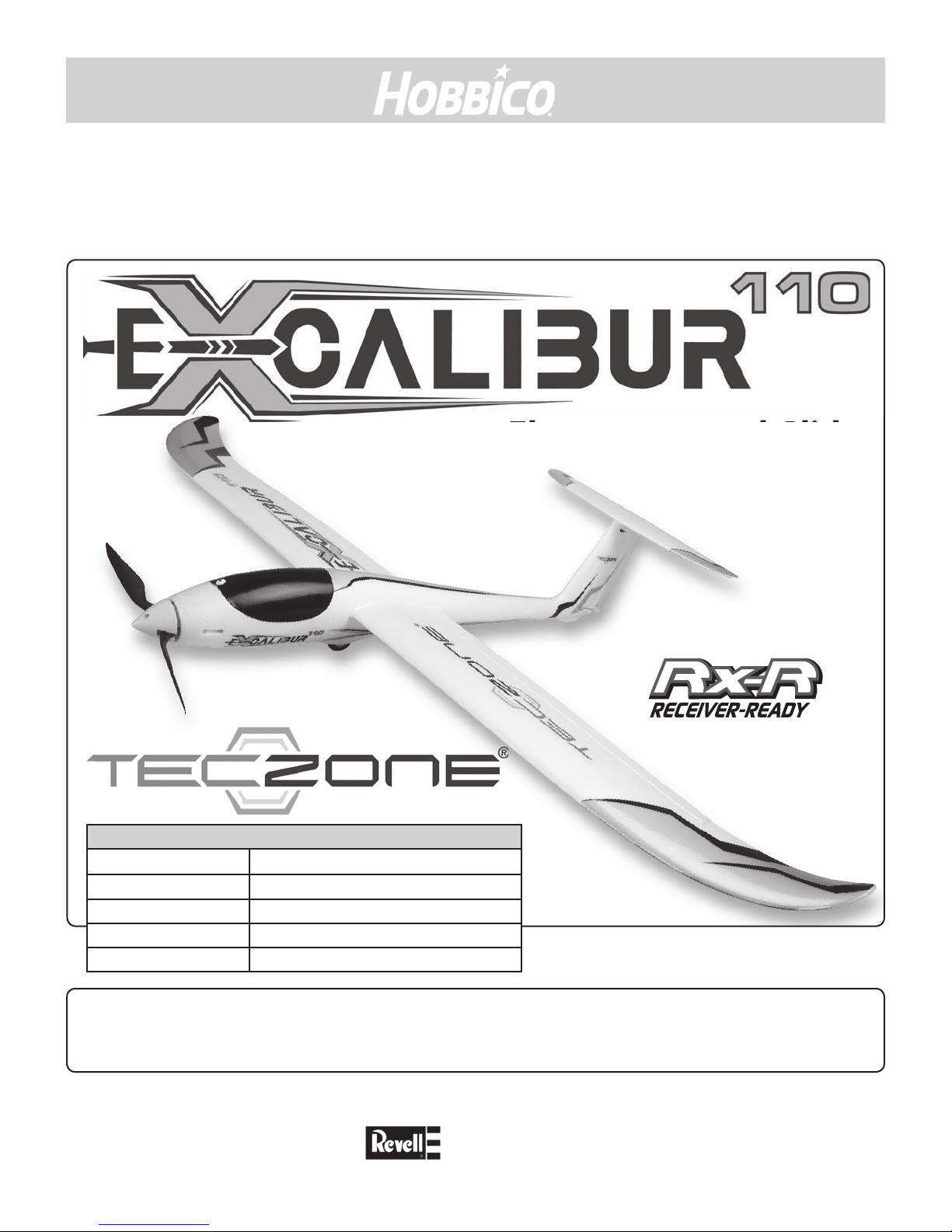
TZNA1100 – E-XCALIBUR 110 - Rx-R
Electro powered Glider
78275 - EN
Technical datas : E-Xcalibur 110 Rx-R
Wingspan 1 100 mm
Length 777 mm
Weight 470 g environ
Radio 4 channel minimum radio system
Battery 3S 1200 mAh LiPo battery (GPMP0836)
Read through this manual before starting construction. It contains important
instructions and warnings concerning the assembly and use of this model.
If the model is given to a third party, always include this instruction manual with the model.
Revell GmbH assumes no responsibility for any printing errors in this manual.
Subject to technical changes !
Version 1.00
™
Distributed by :
www.hobbico.de
Page 2
TABLE OF CONTENTS
General information .............................................................................................................................................................................................................2
Environment protection info ...........................................................................................................................................................................................2
Important notication.........................................................................................................................................................................................................2
Safety instructions ................................................................................................................................................................................................................3
Safety code................................................................................................................................................................................................................................3
General ..................................................................................................................................................................................................................................3
Radio Control ......................................................................................................................................................................................................................3
Introduction .............................................................................................................................................................................................................................3
Warranty .....................................................................................................................................................................................................................................4
Additionnal items required...............................................................................................................................................................................................4
Radio system, battery and charger .............................................................................................................................................................................4
Building Supplies ...............................................................................................................................................................................................................4
Spare parts for the E-Xcalibur 110 .................................................................................................................................................................................4
Replacement parts list .....................................................................................................................................................................................................4
Kit content .................................................................................................................................................................................................................................5
Kit check .....................................................................................................................................................................................................................................5
Preparations .............................................................................................................................................................................................................................5
Wing install ............................................................................................................................................................................................................................... 6
Check the Control Directions ........................................................................................................................................................................................7
ENGLISH
Throws settings .......................................................................................................................................................................................................................8
Balance the Model (C.G.) ....................................................................................................................................................................................................8
Balance the Model Laterally ..........................................................................................................................................................................................9
Charging transmitter batteries .......................................................................................................................................................................................9
Lithium battery handling and usage ..........................................................................................................................................................................9
Balance Propellers ................................................................................................................................................................................................................. 9
Rx antenna layout ..................................................................................................................................................................................................................9
Ground Check .......................................................................................................................................................................................................................... 9
Range Check .............................................................................................................................................................................................................................9
CheckList ................................................................................................................................................................................................................................. 10
Flying the E-Xcalibur 110 ................................................................................................................................................................................................ 10
General ............................................................................................................................................................................................................................... 10
Hand launch start ........................................................................................................................................................................................................... 11
Flying...................................................................................................................................................................................................................................11
Landing .............................................................................................................................................................................................................................. 11
GENERAL INFORMATION
• Read this manual and its safety precautions carefully!
• Keep this manual and if you give the model to a third
party, include this manual with the model.
• Take care, that you are familiar with your transmitter and
all electronic components, used in your plane.
• Take care to ensure the safe operation/use of all tools you
will use to assemble this model.
• Only use glues as recommended for the various parts of
the model you are securing.
• Before assembling please check all parts of this kit. If
some parts are missing or have a mistake, please call our
service center.
2
ENVIRONMENT PROTECTION INFO
This symbol on the product or its packaging indicates this
product must not be disposed of with other household waste.
Instead, it is the user’s responsibility to dispose of their waste
equipment by taking it to a designated waste collection point
for the recycling of waste electrical and
electronic equipment.
For more information of where you can take
your waste equipment for recycling, please
contact your local council.
IMPORTANT NOTIFICATION
Due to its characteristics, the E-Xcalibur 110 requires a certain
level of technical knowledge. Carefully follow the instructions
for assembly and adjustments. We advise you to entirely read
this manual before starting to not overlook any important
step. Be particularly careful to monitor the operation of the
controls before each use and ensure no damage can cause
improper operation of the rudders or motor.
Page 3
Introduction
Thank you for buying the TecZone E-Xcalibur 110. The E-Xcalibur 110 features a powerful outrunner brushless motor. His compact
design, the two wing panels and the removable horizontal stabilizer makes it easy to carry and store. The good ight behavior and
a large speed range will give a lot of fun to beginners, advanced and expert pilots. The ailerons and rudder eciency allows easy
aerobatic ight. You will enjoy your E-Xcalibur 110 on at elds and also for slope ying.
You can nd the last technical updates and manual addendums on the Hobbico Germany web site : www.hobbico.de
Search at "Product Manuals". Select the "TecZone" brand, then the E-Xcalibur 110 model to download the last edition of the
manual.
SAFETY INSTRUCTIONS
Please follow these instructions to ensure the safety of
yourself/others and the model itself.
• 1. Your E-Xcalibur 110 should not be considered a toy, but
rather a sophisticated, working model that functions very
much like a full-size airplane. Because of its performance
capabilities, the E-Xcalibur 110 if not assembled and
operated correctly, could possibly cause injury to yourself
or spectators and damage to property.
• 2. You must assemble the E-Xcalibur 110 according to the
instructions. Do not alter or modify the model, as doing
so may result in an unsafe orunyable model. In a few
cases the instructions may dier slightly from the photos.
In those instances the written instructions should be
considered as correct.
• 3. You must use an R/C radio system that is in good
condition. All components must be correctly installed so
that the model operates correctly on the ground and in
the air. You must check the operation of the model and all
components before every ight.
• 4. If you are not an experienced pilot or have not own
this type of model before, we recommend that you get
the assistance of an experienced pilot in your R/C club
for your rst ights. If you’re not a member of a club, your
local hobby shop has information about clubs in your
area whose membership includes experienced pilots.
• 5. Whilst this model has been ight tested to exceed
normal use, the modeller is responsible for the
reinforcement and/or substitution of hardware as
required if they intend using the model for high-stress
ying, such as racing, or if non-standard motors and/or
batteries in excess of the recommended range are used.
Any modication is done at the modeller’s own risk and
will not be covered by the normal warranty.
TecZone quality
We, as the kit manufacturer, provide you with a top quality,
thoroughly tested kit and instructions, but ultimately
the quality and yability of your nished model depends
on how you build it; therefore, we cannot in any way
guarantee the performance of your completed model,
and no representations are expressed or implied as to the
performance or safety of your completed model.
SAFETY CODE
GENERAL
1) I will not y my model aircraft in sanctioned events,
air shows, or model ying demonstrations until it has
been proven to be airworthy by having been previously,
successfully ight tested.
2) I will not y my model aircraft higher than approximately
400 feet within 3 miles of an airport without notifying the
airport operator. I will give right-of-way and avoid ying in the
proximity of full-scale aircraft. Where necessary, an observer
shall be utilized to supervise ying to avoid having models y
in the proximity of full-scale aircraft.
3) Where established, I will abide by the safety rules for the
ying site I use, and I will not willfully and deliberately y my
models in a careless, reckless and/or dangerous manner.
4) I will not y my model unless it is identied with my name
and address, on or in the model. Note: This does not apply to
models while being own indoors.
5) I will not operate models with pyrotechnics (any device that
explodes, burns, or propels a projectile of any kind).
RADIO CONTROL
1) I will have completed a successful radio equipment ground
check before the rst ight of a new or repaired model.
2) I will not y my model aircraft in the presence of spectators
until I become a qualied ier, unless assisted by an
experienced helper.
3) At all ying sites a straight or curved line(s) must be
established in front of which all ying takes place with the
other side for spectators. Only personnel involved with
ying the aircraft are allowed at or in front of the ight line.
Intentional ying behind the ight line is prohibited.
4) I will operate my model using only radio control frequencies
currently allowed by the laws of the country where I am.
5) I will not knowingly operate my model within three miles of
any pre-existing ying site.
6) Under no circumstances may a pilot or other person touch
a powered model in ight; nor should any part of the model
other than the landing gear, intentionally touch the ground,
except while landing.
ENGLISH
3
3
Page 4
WARRANTY
Hobbico/Revell guarantees this kit to be free from defects
in both material and workmanship at the date of purchase.
This warranty does not cover any component parts damaged
by use or modication. In no case shall Hobbico/Revell's
liability exceed the original cost of the purchased kit. Further,
Hobbico/Revell reserves the right to change or modify this
warranty without notice.
In that Hobbico/Revell has no control over the nal assembly
or material used for nal assembly, no liability shall be
assumed nor accepted for any damage resulting from the
use by the user of the nal user-assembled product. By the
act of using the user-assembled product, the user accepts all
resulting liability.
If the buyer is not prepared to accept the liability associated
with the use of this product, the buyer is advised to return this
kit immediately in new and unused condition to the place of
purchase.
ENGLISH
To make a warranty claim send the defective part or item to
Hobby Services at the address below:
Service-Abteilung Revell GmbH
Henschelstr. 20-30, 32257 Bünde, Germany
Tel: +49 5223 965144
Email: service@hobbico.de
Include a letter stating your name, return shipping address,
as much contact information as possible (daytime telephone
number, fax number, e-mail address), a detailed description
of the problem and a photocopy of the purchase receipt.
Upon receipt of the package the problem will be evaluated as
quickly as possible.
BUILDING SUPPLIES
To build your E-Calibur 110, some tools are required :
❍ Adhesive hokk and loop material
❍ Sharp scissors
❍ Small screwdriver
The following items may help you during assembly. Order
numbers are provided in parentheses.
❍ CG Machine™ (GPMR2400)
❍ GreatPlanes PRO CA medium foam safe (GPMR6069)
❍ GreatPlanes PRO tips (GPMR6033)
❍ CA accelerator spray (GPMR6034)
❍ Great Planes PRO Threadlocker (GPMR6060)
❍ Hobby Knife (39000)
❍ AccuThrow™ Deection Gauge (GPMR2405)
SPARE PARTS FOR THE E-XCALIBUR 260
Spare parts can be obtained from RC hobby retail outlets and
similar online suppliers, most likely the same one you purchased the model from originally. Alternatively, if you need
assistance locating a suitable dealer, please contact Product
Support:
Service Department – Revell GmbH
Henschelstr. 20-30, 32257 Bunde, Germany
Tel. 01805 110111 (only for Germany)
(14 Cent/Min. when called from landline)
(Mobile: max 42 Cent/Min.)
Email: Hobbico-Service@Revell.de
ADDITIONNAL ITEMS REQUIRED
This is a partial list of items required to nish the E-Xcalibur
110 that may require planning or decision-making before
starting to build. Order numbers are provided in parentheses.
RADIO SYSTEM, BATTERY AND CHARGER
To control the E-Xcalibur 110, you will require a minimum
4 channel transmitter and the matching receiver. For best
performance, a computer transmitter is recommended, such
as our 6 channel Tactic TTX50 (TACJ2652). Recommended
items are as follows:
❍ Tactic TR625 2,4 GHz 6 channel diversity receiver
(TACL0825)
❍ ElectriFly 3S 11,1V 1200 mAh 30C LiPo battery
(GPMP0836)
❍ PulseTec354 AC/DC charger (HAP0180)
4
REPLACEMENT PARTS LIST
Missing parts Contact Product support
Manual Contact Product support
Scale 1:1 drawing Not available
Parts listed below Shops/Internet
Référence Désignation
TZNA1101 E-Xcalibur 110 fuselage set
TZNA1102 E-Xcalibur 110 main wing set
TZNA1103 E-Xcalibur 110 tail wing set
TZNA1104 E-Xcalibur 110 folding propeller blades
TZNA1105 E-Xcalibur 110 prop adapter
TZNA1106 E-Xcalibur 110 brushless motor
TZNA1107 E-Xcalibur 110 canopy
TZNA1108 E-Xcalibur 110 8 grams servo
Page 5

KIT CONTENT
1
2
2
4
KIT CHECK
Before starting to build, use the Kit Contents list to take an
inventory of this kit to make sure it is complete and inspect the
parts to make sure they are of acceptable quality. If any parts
are missing or are not of acceptable quality, or if you need assistance with assembly, contact Revell Product Support.
❍ 1 Fuselage with canopy
❍ 2 Wings
❍ 3 Horizontal stabilizer
❍ 4 CFK wing joiner
Parts not shown on the picture :
In addition, the kit include the following items :
3
❍ (1) Wing lock
❍ (1) Nylon wing screw
❍ (1) Horizontal stabilizer screw
❍ (1) Y-Lead
ENGLISH
Service Department – Revell GmbH
Henschelstr. 20-30, 32257 Bunde, Germany
Tel. 01805 110111 (only for Germany)
(14 Cent/Min. when called from landline)
(Mobile: max 42 Cent/Min.)
Email: Hobbico-Service@Revell.de
PREPARATIONS
❏ 1. If not done yet, unpack each part of this kit and check
them all. If any part is defective or missing, please, contact
Revell Product Support.
Service Department – Revell GmbH
Henschelstr. 20-30, 32257 Bunde, Germany
Tel. 01805 110111 (only for Germany)
(14 Cent/Min. when called from landline)
(Mobile: max 42 Cent/Min.)
Email: Hobbico-Service@Revell.de
❏ 1. Set the horizontal stabilizer at the top of the vertical n.
Be sure the positioning pins at the top of the n are correctly
inserted into the holes under the stabilizer.
5
Page 6

❏ 2. Using the provided metal screw, secure the horizontal
stabilizer.
ENGLISH
❏ 3. Connect the provided elevator linkage to the outer hole
of the elevator horn, and to the outer hole on the elevator
servo arm.
WING INSTALL
❏ 1. Route the Y-Lead through the wing opening of the
fuselage and the fuselage canal, so it goes to the front area to
be connected to the receiver.
❏ 2. Remove the protections of the aileron servo linkages
and ensure the servos are correctly secured. If needes, add a
drop of foam safe CA to secure the servos.
6
❏ 3. Insert the carbon wing joiner into one wing panel.
Page 7

❏
❏
❏ 4. Route the wing joiner and the wing panel through the
fuselage opening and connect the servo wire connector onto
one connector of the Y-Lead. Then, insert the other wing panel
over the wing joiner, and connect the servo wire connector
to the other connector of the Y-Lead. While inserting the
wires into the fuselage, push the second wing panel into the
fuselage opening, so that the two panels are touching each
other, and wings are centered into the fuselage.
❏ 6. Insert the front wing latch with the handle in vertical
position. If the handle is not vertical, you can't insert fully the
latch.
ENGLISH
❏ 5. Thread the nylon screw into the fuselage and wings to
keep wings locked and centered into the fuselage.
❏ 7. With the latch fully pushed into the wing, turn the latch
90° clockwise to lock the front of the wings.
❏ 8. Follows your radio system manual to connect the servos
and the ESC to the receiver.
CHECK THE CONTROL DIRECTIONS
During the controls direction check, the motor may start.
We strongly suggest you remove the propeller, to avoid any
accident if the motor start.
❏ 1. Turn the transmitter on, then, power the ESC (and so,
the receiver). Set each channel and every trims to neutral. If
needed, re-locate the servo arms so they are perpendicular to
the servo case.
❏ 2. Check that with every trims at neutral, the control
surfaces are at neutral. If needed, adjust the length of linkages
by turning the clevis.
❏ 3. Make certain that ailerons, elevator and rudder respond
correctly to transmitter input as shown in the diagrams below.
If any of the controls respond in the opposite direction, you
7
Page 8

should correct them by activating the appropriate servo
FULL
THROTTLE
RUDDER
GOES
RIGHT
ELEVATOR
GOES DOWN
LEFT AILERON
GOES DOWN
RIGHT AILERON
GOES UP
4 CHANNELS SETUP
(STANDARD MODE 1)
FULL
THROTTLE
RUDDER
GOES
RIGHT
ELEVATOR
GOES DOWN
LEFT AILERON
GOES DOWN
RIGHT AILERON
GOES UP
4 CHANNELS SETUP
(STANDARD MODE 2)
reverser on your transmitter. Be certain the control surfaces
have remained centred. Adjust if necessary.
THROWS SETTINGS
❏ Use a ruler to accurately measure and set the control throw
of each control surface as indicated in the chart that follows.
NOTE: The throws are measured at the widest part of the
elevators, rudder and ailerons.
Here are the suggested control throws :
ENGLISH
Low rate
(Normal)
Aileron
Elevator
Rudder
Important note
To ensure a successful rst ight, set up your E-Xcalibur 110
according to the control throws speci ed in this manual. The
throws have been determined through actual ight testing
and accurate record-keeping allowing the model to perform
in the manner in which it was intended. If, after you have
become accustomed to the way the E-Xcalibur 110 ies,
you would like to change the throws to suit your taste, that
is ne. However, too much control throw could make the
model too responsive and di cult to control, so remember,
“more is not always better.”
Up and Down
10 mm
Up and Down
8 mm
Left/Right
20 mm
High rate
(For experts)
Up and Down
20 mm
Up and Down
15 mm
Left/Right
20 mm
BALANCE THE MODEL (C.G.)
More than any other factor, the C.G. (balance point) can have
the greatest e ect on how a model ies and may determine
whether or not your rst ight will be successful. If you value
this model and wish to enjoy it for many ights, DO NOT
OVERLOOK THIS IMPORTANT PROCEDURE. A model that is not
properly balanced will be unstable and possibly un yable.
Now, the modèl should be in a "ready to y" status, with all
parts of the model installed and with battery and canopy in
position.
❏ 1. Use a felt tip pen or tape to accurately mark the C.G
(Centre of Gravity) on the bottom of the wing. The E-Xcalibur
110 C.G. is located 40 mm back from the leading edge of
the wing at the wing root. This is where your model should
balance for the rst ights. Later, you may experiment by
shifting the C.G. 8 mm forward or 5 mm back to change the
ying characteristics. In any case, start at the recommended
balance point and do not at any time balance the model
outside the speci ed range.
❏ 2. With all parts of the model installed (ready to y) and
with batteries and canopy in position, place the model on a
Great Planes CG Machine, or on two sticks, or lift at the balance
point you marked on ngers.
8
Page 9

❏ 3. If the tail drops, the model is tail-heavy and you need
to move the ight battery forward. If the nose drops, the
model is nose-heavy and you need to move the ight battery
backward to balance. If moving the ight battery is not
enought, you may attach some weight at the nose or at the
rear of the model. When possible, always start by moving the
ight battery to reduce the weight adding.
❏ 4. If you found it is necessary to add any weight, recheck
the C.G. after the weight has been installed.
BALANCE THE MODEL LATERALLY
❏ 1. You will need an assistant to help you with this procedure.
With the wing level, lift the model by the nose, whilst also
placing a nger under the rear of the fuselage. Do this several
times.
❏ 2. If one wing always drops when you lift the model, it
means that side is heavy. Balance the sailplane by adding
weight to the other wing tip. An airplane that has been laterally
balanced will track better in loops and other maneuvers.
CHARGING TRANSMITTER BATTERIES
Follow the battery charging instructions that came with your
radio control system to charge the batteries. You should always
charge your transmitter the night before you go ying, and at
other times as recommended by the radio manufacturer.
LITHIUM BATTERY HANDLING AND USAGE
WARNING!! Read the entire instructions included with
your ight battery before charging. Failure to do so could
lead to permanent damage of the ight battery and/or its
surroundings, and could cause bodily harm!
• ONLY use a LiPo approved charger. NEVER use a NiCd/
NiMH peak charger!
• NEVER charge in excess of 4.20V per cell.
• ONLY charge through the “charge” or “balance” lead.
NEVER charge through the “discharge” lead.
• NEVER charge at currents greater than 1C.
• ALWAYS set charger’s output volts to match battery volts.
• ALWAYS charge in a reproof location.
• NEVER trickle charge.
• NEVER allow the battery temperature to exceed 65° C.
• NEVER disassemble or modify pack wiring in any way or
puncture cells.
• NEVER discharge below 2.5V per cell.
• NEVER place on combustible materials or leave
unattended during charge or discharge.
• ALWAYS KEEP OUT OF REACH OF CHILDREN.
• NEVER leave the LiPo battery unattended while charging.
If the battery becomes more than just warm, discontinue
charging.
• ALWAYS remove the LiPo battery from the plane before
charging.
BALANCE PROPELLERS
Carefully balance your spare propellers before you y. An
unbalanced prop can be the single most signi cant cause of
vibration that can damage your model. Not only will motor
mounting screws and bolts loosen, possibly with disastrous
e ect, but vibration may also damage your radio receiver and
battery. We use a Top Flite Precision Magnetic Prop Balancer
(TOPQ5700) in the workshop and keep a Great Planes
Fingertip Prop Balancer (GPMQ5000) in our ight box.
RX ANTENNA LAYOUT
The receiver of a 2.4 GHz radio system is tted with one or two
short antennas. Be sure to route the antenna (s) away from
wires and electronic devices installed into the fuselage.
With a 2 antennas receiver, set the antennas as far as possible
one of each other, and set them with a 90° orientaion one of
the other to improve the quality of the signal.
GROUND CHECK
Before every ight, rst inspect the model closely to make
sure that all screws are tight, hinges and pushrods are secure
and propellers are properly tted.
RANGE CHECK
Always ground check the operational range of your radio
before the rst ight of the day. With the transmitter antenna/
aerial collapsed and the transmitter and receiver switched
“ON”, you should be able to walk at least 30m (100’) away from
the model and still have control. Have an assistant stand with
your model and, whilst you move the controls, tell you what
the control surfaces are doing in response. With your assistant
holding the model (being careful to avoid the propellers)
repeat this test with the motors running at various speeds
and have them gesture to indicate what is happening. If the
control surfaces do not respond correctly, DO NOT y! Find
and correct the problem. Look for loose servo connections
and/or broken wires. Poor solder joints in your battery or a
defective cell could also be the cause.
ENGLISH
9
Page 10

CHECKLIST
Just prior to taking o, your mind may be elsewhere,
anticipating the excitement of your rst ight with the
E-Xcalibur 110. This could cause you to overlook certain
checks and procedures that should always be performed
before the model is own. To help avoid this, we’ve put
together a basic checklist to make sure that important
pre-ight checks are not overlooked. Additionally, many
are covered in more detail in other parts of this instruction
manual. Be sure to check them o as each check is
completed.
❍ 1. Always check that all motors are securely attached.
❍ 2. Check the C.G. according to the measurements
provided in this manual.
❍ 3. Check your transmitter’s antenna.
❍ 4. Balance the model laterally as detailed in this manual.
❍ 5. Tighten the propeller nut.
ENGLISH
❍ 6. With motors disarmed, turn the propeller one full
revolution to ensure it is moving freely.
❍ 7. Add a drop of oil to each wheel axle to ensure wheels
turn freely.
❍ 8. Make sure all hinges are securely glued in place.
❍ 9. Check that each rudder arm is secured.
❍ 10. Check that every linkage is secured.
❍ 11. Ensure all servo arms are secured to their servos with
their respective screws.
❍ 12. Make sure servo wires do not interfere with any
moving parts and double-check all connections are
secure.
❍ 13. Balance all propellers.
❍ 14. Make sure the canopy and cowls are secured.
❍ 15. Include your name, address and telephone number
somewhere inside the model.
❍ 16. Range check your radio when you get to the ying
site.
❍ 17. Conrm that all control functions operate in the
correct direction and that throws are set up according to
this manual.
❍ 18. Use threadlocking compound to secure all critical
metal to metal fasteners, such as the set screws that hold
the wheel axles to the wheel struts, etc.
❍ 19. Reinforce holes for wood screws with small amounts
of CA glue, as this helps prevent cracking, etc.
❍ 20. Check for foreign bodies that may have entered the
motor housing.
❍ 21. If you wish to photograph your model, do so before
your rst ight.
FLYING THE E-XCALIBUR 110
GENERAL
The E-Xcalibur 110 is a great-ying model that ies smoothly
and predictably. However, it is not a model for beginners, it
have a wide speed range and a lot of power, and is intended
for pilots with an intermediate RC experience. If the E-Xcalibur
110 is your 1st RC model, or if your experience is low, you need
to be assisted by an experienced modeller, able to take control
if needed. An experienced pilot may avoid a critical situation
and you will enjoy more quicky your E-Xcalibur 110.
For the rst ights, ask to an assistant to launch the model, so
you can keep your hands on the radio, to to be ready to correct
path deviations. Later, with the model perfectly set (trimmed),
you will be able to launch the E-Xcalibur by yourself.
Always remember to comply with the local laws and regulations
regarding the operation of radio controlled models. Read also
all the safety instrucions at the beginning of this manual.
CAUTION (Applies to all RC aircraft): If, whilst ying, you
notice an alarming or unusual sound like a low-pitched
“buzz”, this may indicate control surface utter. Flutter
occurs when a control surface (such as aileron or elevator)
or a ying surface (such as wing or stabilizer) rapidly vibrates
up and down (thus causing the noise). In extreme cases, if
not detected early enough, utter can actually cause the
ying surface to fail and detach, thus causing a loss of
control and potential crash. The best thing to do if utter is
detected is to land as soon as safely possible. Identify which
surface uttered so that the problem can be resolved. Check
all servo grommets for signs of deterioration or vibration.
Make sure all pushrod linkages are free of excess play. If a
surface uttered once, under similar circumstances, it will
probably utter again unless the problem is xed. Things
that can cause utter include; Excessive hinge gap, Not
mounting control horns solidly, Side-play of wire pushrods
(caused by large bends), Excessive free-play in servo gears
(wear) and Unsecured servo mountings. The most common
cause of utter is ying an overpowered model at excessive
speed!
10
Page 11

HAND LAUNCH START
Before launching, be sure that the battery is fully charged
and all control surfaces are working properly. Any negligence
on these checks can result in a crash and damages to the
model.
Always lauch the model directly to the wind. When you are
ready, set throttle at 75% and launch with a good impulse
directly to the wind. The acceleration is quick. The model climb
with a 30-40° angle. At full throttle, with a small elevator input,
the E-Xcalibur 110 can climb vertically. Have in mind that the
pilot should keep concentrated, because the model may be
very high in a very short time.
FLYING
For reassurance and to keep an eye on other trac, it is a
good idea to have an assistant on the ight line with you. If
you choose to y with motor active, tell him to remind you to
throttle back once the plane gets to a comfortable altitude.
While a lot of throttle is usually desirable for takeo, the
E-Xcalibur y more smoothly at reduced speeds and only
need a little power to maintain altitude.
Take it easy with the E-Xcalibur 110 for the rst few ights,
gradually getting acquainted with it as you gain condence.
Adjust the trims to maintain straight ight and a smooth
gliding path. After ying around for a while, and while still at a
safe altitude, practice slow ight and execute practice landing
approaches. Makes also few low fast passes, followed by full
throttle climbs, and then, dive with motor o. Propeller folded,
the model reaches his maximum speed.
Practice dierent maneuvers and ask to your assistant to notice
the changes to make to the settings (C.G., Throws, expo...) to
remember them after the ight. Mind your battery level, but
use this rst ight to become familiar with your model before
landing.
One nal note about ying your model. Have a goal or
ight plan in mind for every ight. This can be learning a new
maneuver(s), improving a maneuver(s) you already know, or
learning how the model behaves in certain conditions (such
as on high or low rates). This is not necessarily to improve your
skills (though it is never a bad idea!), but more importantly
so you do not surprise yourself by impulsively attempting a
maneuver and suddenly nding that you’ve run out of time,
altitude or airspeed. Every maneuver should be deliberate,
not impulsive. For example, if you’re going to do a loop,
check your altitude, mind the wind direction (anticipating
rudder corrections that will be required to maintain heading),
remember to throttle back at the top, and make certain you
are on the desired rates (high/low rates). A ight plan greatly
reduces the chances of crashing your model just because of
poor planning and impulsive moves. Remember to think.
Have a ball!
ENGLISH
But always stay in control and y in
a safe manner.
GOOD LUCK AND
GREAT FLYING!
LANDING
Prepare landing by a downwind leg at an 20-30 m altitude.
With motor shutted down and retracted, set landing gear
down. Allow the nose of the model to pitch downward slightly
to gradually bleed o altitude. Continue to lose altitude, but
maintain airspeed by keeping the nose down as you turn
onto the crosswind leg. If you are too long, or if the approach
is not correct, don't wait to be very low, restart the motor
and and climb out to make another attempt. When you’re
ready to make your landing are and the model is a foot or
so o the deck, smoothly increase up elevator until it gently
touches down. Once the model is on the runway and has lost
ying speed, hold up elevator to place the tail on the ground.
Using ailerons, keep wings level as long as you can. Note :
This model lose few altitude with motor o, so, you may need
some attemps before your rst successfull approach, so, keep
energy into your battery to be able to make several attemps.
11
Page 12

Distributed by :
www.hobbico.de
 Loading...