

Hobbico TWINSTAR, TWINSTAR ARF Instruction Manual
WARRANTY
Hobbico®guarantees this kit to be free from defects in both material and workmanship at the date of purchase.This warranty does
not cover any component parts damaged by use or modification. In no case shall Hobbico’s liability exceed the original cost of
the purchased kit. Further, Hobbico reserves the right to change or modify this warranty without notice.
In that Hobbico has no control over the final assembly or material used for final assembly, no liability shall be assumed nor accepted
for any damage resulting from the use by the user of the final user-assemb led product.By the act of using the user-assemb led product,
the user accepts all resulting liability.
If the buyer is not prepared to accept the liability associated with the use of this product, the buyer is advised to return this
kit immediately in new and unused condition to the place of purchase.
To make a warranty claim send the defective part or item to Hobby Services at the address below:
Hobby Services
3002 N. Apollo Dr. Suite 1
Champaign IL 61822
USA
Include a letter stating your name, return shipping address, as much contact information as possible (daytime telephone number, fax
number, e-mail address), a detailed description of the problem and a photocopy of the purchase receipt. Upon receipt of the package
the problem will be evaluated as quickly as possible.
READ THROUGH THIS MANUAL BEFORE STARTING
CONSTRUCTION.IT CONT AINS IMPORTANT INSTRUCTIONS
AND WARNINGS CONCERNING THE ASSEMBLY AND
USE OF THIS MODEL.
HCAZ3076 for HCAA2076 V1.0 Entire Contents © Copyright 2004
Champaign, IL
(217) 398-8970
E-mail:
airsupport@hobbico.com
INSTRUCTION MANUAL
Wingspan: 56 in [1420mm]
Wing Area: 560 sq in [36.1dm
2
]
Weight: 5-5.5 lb [2270 – 2490g]
Wing Loading: 21 – 23 oz/sq ft [64 – 70g/dm
2
]
Length: 40 in [1015mm]
Radio: 4-Channel with five servos
Engine: .15-.25 cu in [2.5-4cc] two-stroke, .26-.40 cu in
[4.5-6.5cc] four-stroke
™
INTRODUCTION................................................................2
AMA ...................................................................................2
SAFETY PRECAUTIONS..................................................2
ADDITIONAL ITEMS REQUIRED.....................................3
Hardware & Accessories .............................................3
Adhesives & Building Supplies....................................3
Covering Tools .............................................................3
Optional Supplies & Tools............................................3
IMPORTANT BUILDING NOTES.......................................3
ORDERING REPLACEMENT PARTS...............................4
METRIC/INCH RULER ......................................................4
KIT CONTENTS .................................................................5
PREPARATIONS................................................................6
BUILDING INSTRUCTIONS..............................................6
Hinge the Control Surfaces..........................................6
Join the Wing Halves...................................................7
Mount the Engines .......................................................8
Assemble & Install the Fuel Tanks...............................9
Mount the Tail.............................................................10
Finish the Wing..........................................................12
Install the Radio Gear................................................15
Install the Landing Gear ............................................16
Mount the Receiver & Battery....................................18
Apply the Decals ........................................................18
GET THE MODEL READY TO FLY..................................19
Check the Control Directions.....................................19
Set the Control Throws..............................................19
Balance the Model (C.G.)..........................................19
Balance the Model Laterally......................................20
PREFLIGHT.....................................................................20
Identify Your Model.....................................................20
Charge the Batteries ..................................................20
Balance the Propellers...............................................21
Ground Check............................................................21
Range Check.............................................................21
ENGINE SAFETY PRECAUTIONS.................................21
AMA SAFETY CODE (excerpts)....................................21
CHECK LIST ....................................................................22
FLYING.............................................................................23
Takeoff .......................................................................23
Flight..........................................................................23
Landing......................................................................23
The Hobbico TwinStar
™
ARF is a fun, exciting sport twin
aircraft. It makes a terrific first twin or “twin trainer” to help
you get ready to fly more true-to-scale and also more
challenging-to-fly twins such as a DC-3, or it simply can be
a really fun twin aircraft for the average sport pilot. ENJOY!
For the latest technical updates or manual corrections to the
TwinStar visit the Hobbico web site at
www.hob bico .com
.Open
the “Airplanes”link, then select the TwinStar ARF.If there is new
technical information or changes to this model a “tech notice”
box will appear in the upper left corner of the page.
We urge you to join the AMA (Academy of Model
Aeronautics) and a local R/C club. The AMA is the
governing body of model aviation and membership is
required to fly at AMA clubs. Though joining the AMA
provides many benefits, one of the primary reasons to join
is liability protection. Coverage is not limited to flying at
contests or on the club field. It even applies to flying at
public demonstrations and air shows.Failure to comply with
the Safety Code (excerpts printed in the back of the
manual) may endanger insurance coverage. Additionally,
training programs and instructors are available at AMA club
sites to help you get started the right way. There are over
2,500 AMA chartered clubs across the countr y.Contact the
AMA at the address or toll-free phone number below:
IMPORTANT!!! Two of the most impor tant things you can
do to preserve the radio controlled aircraft hobby are to
avoid flying near full-scale aircraft and avoid flying near or
over groups of people.
1.Your TwinStar should not be considered a toy, but rather
a sophisticated, working model that functions very much
like a full-size airplane.If the TwinStar is not assembled and
operated correctly, it could possibly cause injury to you or
spectators and damage to property.
2. You must assemble the model according to the
instructions.Do not alter or modify the model, as doing so may
result in an unsafe or unflyable model. In a few cases the
instructions may differ slightly from the photos. In those
instances the written instructions should be considered correct.
3.You must take time to build straight, true and strong.
PRO TECT YOUR MODEL,Y OURSELF
& OTHERS...FOLLOW THESE
IMPORTANT SAFETY PRECAUTIONS
Academy of Model Aeronautics
5151 East Memorial Drive
Muncie, IN 47302
Tele: (800) 435-9262
Fax (765) 741-0057
Or via the Internet at:
http://www.modelaircraft.org
AMA
INTRODUCTION
TABLE OF CONTENTS
2

4. You must use an R/C radio system that is in first-class
condition, and a correctly sized engine and components
(fuel tank, wheels, etc.).
5.You must install all R/C and other components so that the
model operates correctly on the ground and in the air.
6.You must check the operation of the model before every
flight to ensure that all equipment is operating and that the
model remains structurally sound.Be sure to check clevises
or other connectors often and replace them if they show any
signs of wear or fatigue.
7. If you are not an experienced pilot or have not flown this
type of model before, we recommend that you get the
assistance of an experienced pilot in your R/C club for your
first flights. If you’re not a member of a club, your local
hobby shop can help you find a club and e xperienced pilots.
Remember:Take your time and follow the instructions to
end up with a well-built model that is straight and true.
This is the list of hardware and accessories required to
finish the Twinstar ARF. Order numbers are provided
in parenthesis.
❏ Y-harness (HCAM2751 for Futaba
®
)
❏ R/C foam rubber 1/2" [13mm] (HCAQ1050)
❏ 3' [900mm] Standard silicone fuel tubing (GPMQ4131)
❏ 1/2 oz. [15g] Thin Pro CA (GPMR6001)
❏ 1/2 oz. [15g] Medium Pro CA+ (GPMR6007)
❏ Pro 30-minute epoxy (GPMR6047)
❏ Pro 6-minute epoxy (GPMR6045)
❏ Drill bits: 1/16" [1.6mm] and 5/32" [4mm]
❏ 4-40 Tap and drill set (GPMR8101)
❏ Tap handle (GPMR8120)
❏ Stick-on, segmented lead weights (GPMQ4485)
❏ Top Flite
®
MonoKote®sealing iron (TOPR2100)
❏ Top Flite Hot Sock
™
iron cover (TOPR2175)
❏ 2 oz. [57g] Spray CA activator (GPMR6035)
❏ CA applicator tips (HCAR3780)
❏ CA debonder (GPMR6039)
❏ Epoxy brushes (6, GPMR8060)
❏ Mixing sticks (50, GPMR8055)
❏ Mixing cups (GPMR8056)
❏ Builder’s Triangle Set (HCAR0480)
❏ Curved-tip canopy scissors for trimming plastic
parts (HCAR0667)
❏ Pliers with wire cutter (HCAR0630)
❏ Robart
®
Super Stand II (ROBP1402)
❏ Masking tape (TOPR8018)
❏ Denatured alcohol (for epoxy clean up)
❏ Dead Center
™
Engine Mount Hole Locator (GPMR8130)
❏ AccuThrow
™
Deflection Gauge (GPMR2405)
❏ CG Machine
™
(GPMR2400)
Descriptions of machine screws include the number of
threads per inch and a length. Example: 4-40 x 3/4" [19mm].
That describes a number four screw that is 3/4" long with
forty threads per inch.
• When you see the term
test fit
in the instructions, it
means that you should first position the part on the
assembly without using any glue. If necessary, modify the
part to ensure the best fit.
• Whenever the term
glue
is written you should rely upon
your experience to decide what type of glue to use.When a
specific type of adhesive works best for that step, the
instructions will make a recommendation.
• Whenever just
epoxy
is specified you may use 6-minute,
30-minute or 45-minute epoxy. When 30-minute epoxy is
specified it is highly recommended that you use only 30-minute
(or 45-minute) epoxy, because you will need the working time
and/or the additional strength.
•
Photos
and
sketches
are placed before the step they
refer to. In many cases, you can get a different look at the
same parts by looking at photos in following steps.
IMPORTANT BUILDING NOTES
Optional Supplies & Tools
Covering T ools
Adhesives & Building Supplies
Hardware & Accessories
ADDITIONAL ITEMS REQUIRED
We, as the kit manufacturer, provide you with a topquality, thoroughly tested kit and instructions, but
ultimately the quality and flyability of your finished model
depends on how you build it;therefore, we cannot in any
way guarantee the performance of your completed
model, and no representations are expressed or implied
as to the performance or safety of your completed model.
3
4
E-Replacement parts for the Hobbico TwinStar ARF are availab le using the order numbers in the Replacement P arts List
that follows.The fastest, most economical service can be provided by your hobby dealer or e-mail order company.
To locate a hobby dealer, visit the Hobbico web site at
www.hobbico.com
. Choose “Where to Buy” at the bottom of the
menu on the left side of the page.Follow the instructions provided on the page to locate a U.S., Canadian or International
dealer. If a hobby shop is not available, replacement parts may also be ordered from Tower Hobbies at
www.towerhobbies.com
, or by calling toll free (800) 637-6050.
Parts may also be ordered directly from Hobby Services by calling (217) 398-0007, or via f acsimile at (217) 398-7721, but
full retail prices and shipping and handling charges will apply.Illinois and Nevada residents will also be charged sales tax.
If ordering via fax, include a Visa®or MasterCard®number and expiration date for payment.
If ordering via mail, send parts orders and payments by personal check to:
Hobby Services
3002 N Apollo Drive, Suite 1
Champaign IL 61822
Be certain to specify the order number exactly as listed in the Replacement Parts List. Payment by credit card or
personal check only; no C.O.D.
If additional assistance is required for any reason, contact Product Support by e-mail at
productsupport@hobbico.com
,
or by telephone at (217) 398-8970.
Replacement Parts List
Order Number Description How to Purchase
Missing pieces.....................Contact Product Suppor t
Instruction manual...............Contact Product Support
HCAA3750 Wing Set
HCAA3751 Fuselage
HCAA3752 Tail Set
HCAA3753 Spinner (2 pcs.)
HCAA3754 Landing Gear
HCAA3755 Nacelle Set (Left & Right)
HCAA3756 Nacelle Cover (2 pcs.)
HCAA3757 Nose Cone
HCAA3758 Fuel Tank
HCAA3759 Decal Set
ORDERING REPLACEMENT PARTS
................
Contact Your Hobby
Supplier to Purchase
These Items
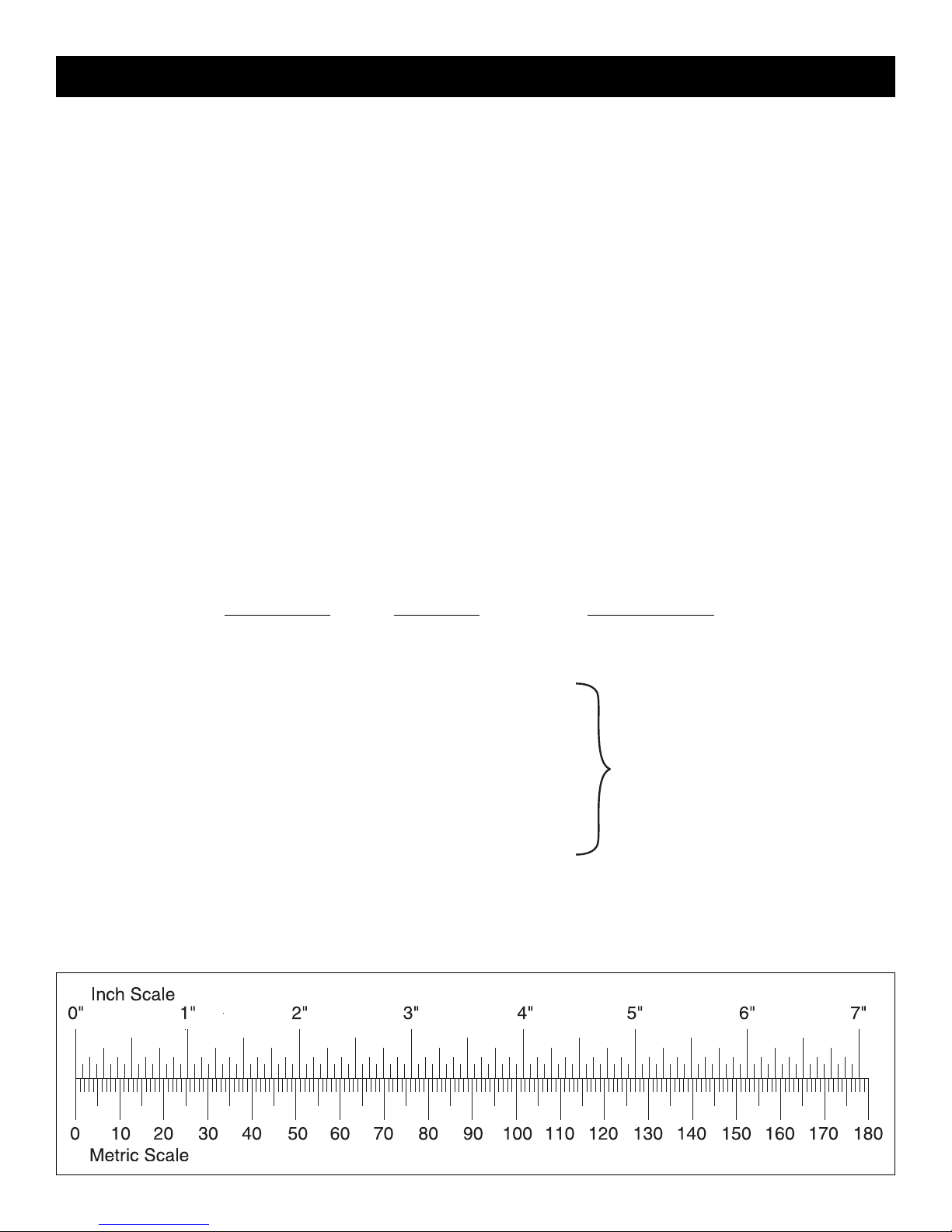
To convert inches to millimeters, multiply inches by 25.4

5
1. Fuselage
2. Fin & Rudder
3. Stabilizer & Elevator
4. Left Wing & Aileron
5. Right Wing & Aileron
6. Hook & Loop Material
7. Wing Joiner (3)
8. Servo Mounts
9. Nose Gear Pushrod Support
10. Wing Bolt Plate
11. Engine Mounts
12. Fuel Tank (2)
13. Right Engine Nacelle
14. Right Nacelle Cover
15. Nose Cone
16. Left Nacelle Cover
17. Left Engine Nacelle
18. Nose Gear
19. Main Landing Gear (2)
20. 2-3/4" [70mm] Wheels (3)
21. Pushrods
Kit Contents (not photographed)
Kit Contents
(2) Large Control Horn
(6) Nylon Clevis
(2) Aileron Torque Rod Horn
(4) 2-56 x 1/2" [13mm] Machine Screw
(6) Nylon FasLink
(1) Screw-Lock Pushrod Connector
(1) Nylon Retainer
(1) 4-40 x 1/4" [6mm] Socket Head Screw
(6) Silicone Retainer
(7) 5/32" [4mm] Wheel Collar
(6) 6-32 Set Screw
(1) 6-32 x 1/4" [6mm] Socket Head
Cap Screw
(1) Nylon Steering Arm
(1) Nylon Nose Gear Mount
(4) 4-40 x 1/2" [13mm] Bolt
(28) #4 Washer
(16) 4-40 x 3/4" [19mm] Socket Head
Cap Screw
(16) #4 Lock Washer
(2) 1/4-20 x 2" [50mm] Nylon Bolt
(1) Landing Gear Strap
(8) #4 x 1/2" [13mm] Screw
(12) #2 x 3/8" [9.5mm] Screw
(12) #2 Washer
Before starting to build, take an inventory of this kit to make sure it is complete, and inspect the parts to make sure they
are of acceptable quality. If any parts are missing or are not of acceptable quality, or if you need assistance with assembly,
contact Product Support.When reporting defective or missing parts, use the part names exactly as they are written in the
Kit Contents list.
Hobbico Product Support
3002 N Apollo Drive, Suite 1
Champaign, IL 61822
Telephone: (217) 398-8970, ext. 5
Fax:(217) 398-7721
E-mail:
airsupport@hobbico.com
KIT CONTENTS
1
2
7
6
3
4
5
8
10
9
11
10
12
13
14
15
16
20
19
21
18
17
11
❏ 1. If you have not yet done so already, remove the major
parts of the kit from the box (wings, fuse, tail parts, etc.) and
inspect them for damage. If any parts are damaged or
missing, contact
Product Support
as listed on page 5.
❏ 2. Remove the masking tape and separate the ailerons from
the wing, the rudder from the fin and the elevator from the stab.
Where necessary, use a covering iron set for low temperature
covering materials, with a covering soc k, to tighten any cov ering
that may have loosened during storage or from removing the
masking tape. Apply pressure over sheeted areas to
thoroughly bond the covering to the wood.
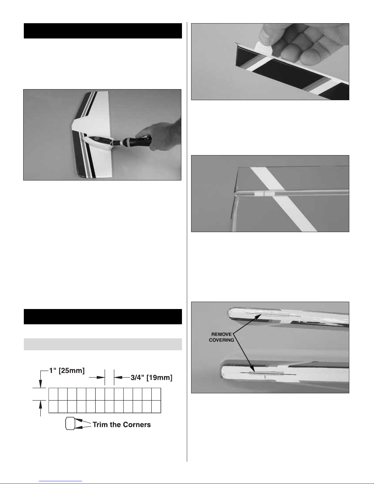
❏ 1. Cut nineteen 3/4" x 1" [19 x 25mm] hinges from the 2"
x 9" [50 x 230mm] CA hinge strip. Snip the cor ners off so
they go in easier.
❏ 2.Test fit four hinges into the hinge slots of both ailerons
and both wings. If you have difficulty inserting the hinges,
insert a #11 blade into the slot and carefully move it back
and forth to slightly widen the slot.
❏ 3. Test fit the ailerons to the wing with the hinges.
❏ 4. Separate the ailerons from the wing and take out all
the hinges.
❏ 5. Cut a small str ip of covering from both sides of each
hinge slot.If this is not done, the covering may interf ere with
the penetration of the CA into the slot and the movement of
the aileron.
❏6. Fit the hinges to the ailerons.Be sure that slightly less than
half the hinge is within the aileron, and the hinge is straight.
Hinge the Control Surfaces
BUILDING INSTRUCTIONS
PREPARATIONS
6
❏ 7. Mix a small amount of epoxy. Coat the inside of the
aileron torque rod holes with epoxy. DO NOT put epoxy in
the hinge slots.
❏ 8. Fit the ailerons to the wings with the hinges and the
torque rods. Adjust the aileron so there is a small gap–just
enough to see light through or to slip a piece of paper
through–between the aileron and the wing. Remove any
excess epoxy with a paper towel dampened with denatured
rubbing alcohol.
❏ 9. Apply six drops of thin CA to the top and bottom of
each hinge. Do not use CA accelerator. After the CA has
fully hardened, test the hinges by pulling on the ailerons.
❏ 10. Install the right aileron, elevator and the rudder using
the same technique as the ailerons.
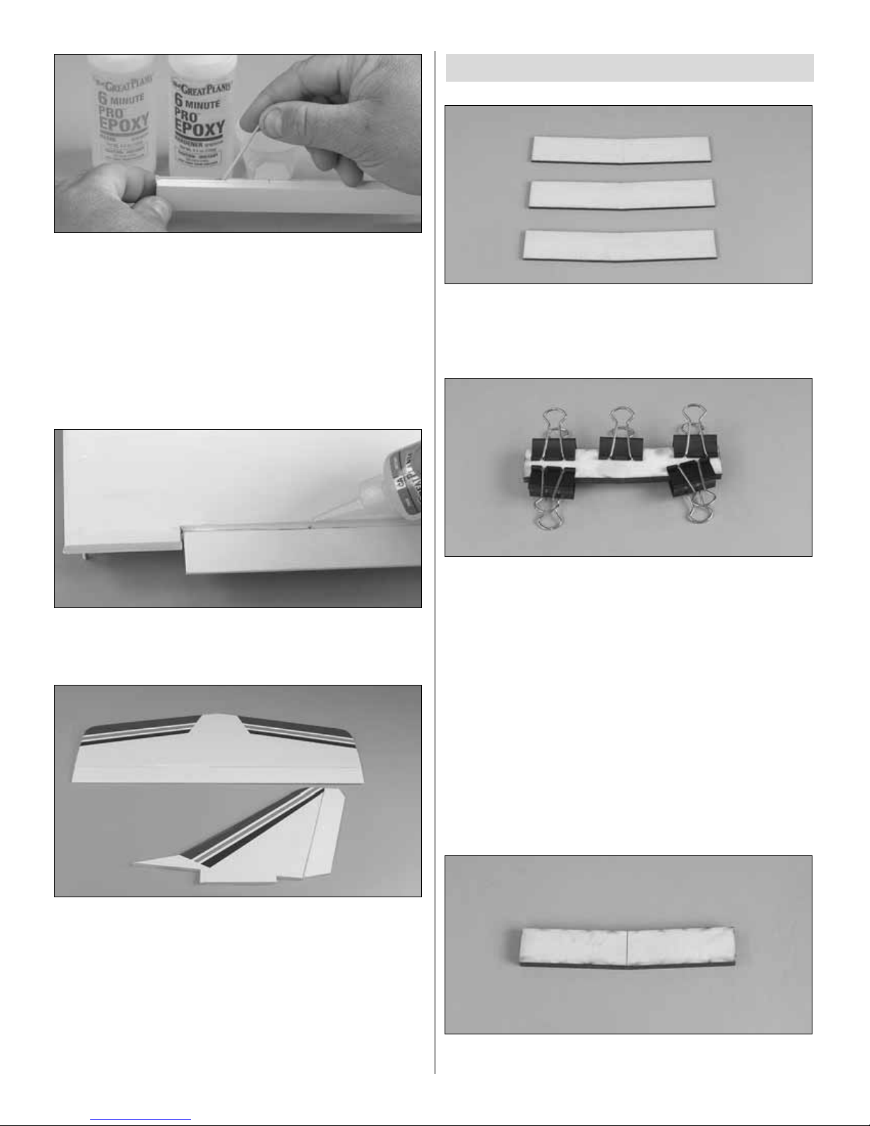
❏ 1. Locate the three 1/8" [3mm] die-cut plywood wing
joiners. Arrange the joiners in the same orientation as they
will be glued together.
❏ 2. Mix approximately 1/4 oz. [7.5ml] of 30-minute epoxy.
Using a mixing stick or epoxy brush, apply an even coat of
epoxy on both sides of one of the wing joiners. Sandwich
this coated joiner between the remaining two joiners.
Quickly proceed through the following steps (3 and 4) bef ore
the epoxy hardens.
❏ 3. Excess epoxy will squeeze out of the seams between
the joiners and must be removed before the epoxy is
allowed to cure. Use a paper towel dampened with rubbing
alcohol to remove any excess epoxy.
❏ 4. Use clamps to fir mly hold the wing joiners together. If
any more epoxy squeezes out, remove it using a paper
towel. Make sure that the joiners are evenly lined up with
each other.
❏ 5. After the epoxy has hardened, remove the clamps.
Draw a centerline on both sides of the plywood wing joiner.
Join the Wing Halves
7
❏ 6.Test fit the wing joiner into both wing panels.The joiner
should slide in with little resistance up to the centerline.Test
fit the wing panels together, making sure that they are flush
without any gaps.
❏ 7. Confir m the dihedral is between 2-1/4" and 2-3/4" [55
and 70mm] measured from the center of one wing tip to the
work bench with the other wing panel flat on the bench. If
your wing’s dihedral is outside this range, please contact
Product Support.
❏ 8. Mix 3/4oz [25ml] of 30-minute epoxy to glue the wing
together. Liberally coat the inside of the left wing joiner
pocket and left root rib. Fit the joiner into the joiner pocket.
Be sure the joiner is in the correct orientation to the wing to
provide the proper dihedral angle.
❏ 9. Fit the right wing half over the joiner.Clean the excess
epoxy from the outside of the wing using a paper towel
dampened with denatured rubbing alcohol. Use clamps and
several strips of masking tape to hold the panels
securely together.
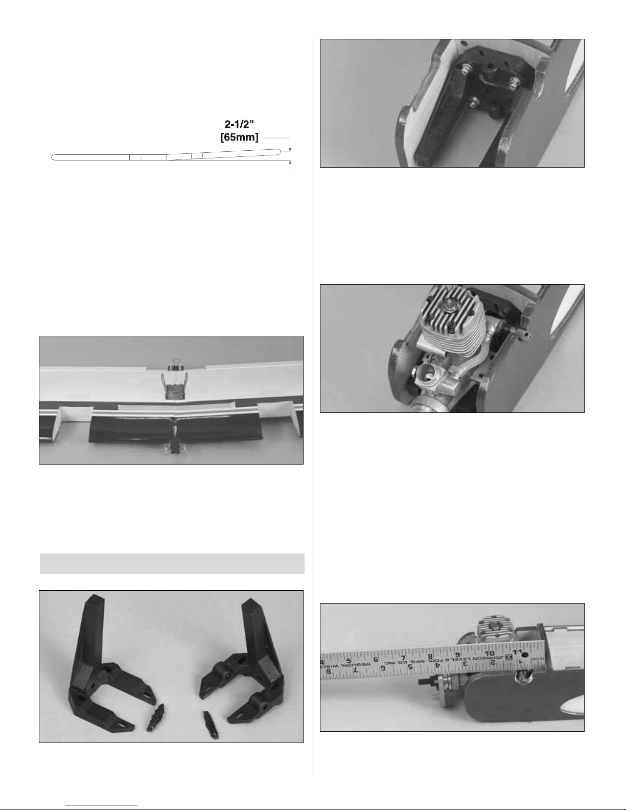
❏❏1. Trim the spreader bars from both halves of one
engine mount.
❏❏2. Mount the engine mount to the left firewall with four
4-40 x 3/4" [19mm] socket head cap screws , #4 flat washers
and #4 lock washers.Do not fully tighten the bolts.
❏❏3. Adjust the width of the mount to fit the engine.
Tighten the mounting bolts.
❏❏4. Place the backplate of the spinner on the engine.
Note: Depending on your engine choice, it may be
necessary to enlarge the hole in the backplate.
❏❏5. Use a few drops of medium CA to tack glue the
engine to the mount with the backplate of the spinner 3-3/4"
[95mm] from the firewall.
Mount the Engines
8
 Loading...