

Page 1
™
™
2.4GHz Radio Adapter2.4GHz Radio Adapter
INSTRUCTION
MANUAL
The AnyLink SLT 2.4GHz Radio
Adapter allows nearly any R/C transmitter
(Tx) to bind with Tactic’s ultra-small, lightweight,
and inexpensive 2.4GHz receivers (Rx). Futaba® and
Hitec® brand transmitters must have a trainer jack. JR® and Spektrum®
transmitters must have a charge jack and trainer/D.S.C. jack. See page
15 for a Tx compatibility chart. Such transmitters can originally be
designed for use on 72MHz, 2.4GHz, FM, PCM, etc. The acceptable
flying range with AnyLink and a Tactic receiver is 1000 feet.
Read this manual in its entirety before use!
Damage resulting from misuse or modifi cation will
void your warranty.
ITEMS INCLUDED
(1) AnyLink 2.4GHz Radio Adapter
(1) Futaba Square Adapter Cable
(1) JR/Spektrum Adapter Cable
(2) Lengths of hard locking adhesive strips
1"(25.4mm) x 1.5" (38mm)
TACJ2000 AnyLink Mnl.indd 1TACJ2000 AnyLink Mnl.indd 1 10/26/2011 1:04:26 PM10/26/2011 1:04:26 PM
Page 2

MOUNTING ANYLINK
Mount AnyLink high on the rear of the Tx, and extend its antenna to
point upwards from the top of the Tx as much as possible. Rotate
the antenna as shown above. Two strips of hard locking fasteners
are included for attaching AnyLink to the rear of the host Tx.
INPUT POWER AND TRANSMITTER CONNECTIONS
Cables are included for attaching AnyLink to Futaba radios having
a square trainer jack, and compatible JR/Spektrum radios. Other
cables are available separately (see page 9). The cable with two
connectors is for Futaba. The cable with three connectors is for JR
and Spektrum. Using the appropriate cable, connect AnyLink to
the Tx as explained below.
Input Power Connection: AnyLink
requires power to be taken from
the host Tx through the appropriate
cable. Insert the cable’s universalstyle servo plug into AnyLink’s INPUT
jack. Make sure the Tx battery is fully
charged prior to operation. Replace
weak alkaline batteries, or fully charge rechargeable batteries before
attempting a flight.
Futaba and Hitec Transmitters: Connect the cable’s trainer plug
to the Tx trainer jack. This connection will provide both power and
signal from the Tx to AnyLink.
2
Input Jack
Cable
TACJ2000 AnyLink Mnl.indd 2TACJ2000 AnyLink Mnl.indd 2 10/26/2011 1:04:27 PM10/26/2011 1:04:27 PM
Page 3

An optional cable is required
to connect Hitec’s
Tx module pins
Aurora Tx to AnyLink
(see page 9). Remove
the antenna and module
from the Aurora Tx.Once
connected to AnyLink, attach
the cable’s second connector to the three
left-most module pins on the rear of the Tx,
Hitec Aurora Tx
as shown. Make SURE the metal terminals on
the cable face upwards when connecting to the Tx.
WARNING: Failure to insert the cable connector properly
can damage the AnyLink and the transmitter!
JR and Spektrum Transmitters: Connect the cable’s “Signal
Plug” to the transmitter’s trainer/D.S.C. jack, as shown below. This
should cause the Tx logic circuit to turn on automatically, which is
normal, and create the signal connection from the Tx to AnyLink.
Do NOT connect the remaining power plug to the Tx at this time.
JR/Spektrum Tx
Power plug
(Charge jack)
Signal plug (DSC)
IMPORTANT! Make sure all connections between
AnyLink and the host Tx are solid physically and cannot
easily become dislodged at any time. Otherwise, power or
signal loss could occur resulting in a loss of control of the
aircraft. Never operate a model with weak Tx batteries as loss
of control could result!
3
TACJ2000 AnyLink Mnl.indd 3TACJ2000 AnyLink Mnl.indd 3 10/26/2011 1:04:27 PM10/26/2011 1:04:27 PM
Page 4
ANYLINK OPERATION
IMPORTANT! Remove the propeller from the airplane
prior to operating AnyLink with the radio system.
Failure to do so could result in personal injury if the motor
unexpectedly turns during setup.
1. Remove the Rf module or crystal from the host Tx if possible.
Leave the Tx’s own antenna in a retracted or folded position.
AnyLink’s own antenna will transmit the signal to the Tactic Rx.
2. Make sure 72MHz computer radios are set to PPM mode.
3. Move the Tx throttle stick to the minimum position.
4. Futaba and Hitec transmitters:
the option to transmit a signal when Tx power is turned ON, make
sure “YES” is selected. Turning the Tx power switch ON will supply
power to the Tx and AnyLink simultaneously. Listen for AnyLink to
beep ONCE when power is applied to confirm it’s configured for
Futaba/Hitec transmitters. Turn the Tx power switch ON and listen for
tones from AnyLink. If AnyLink beeped twice, skip to the CHANNEL
MAPPING section below. Otherwise, skip to step 6.
5. JR and Spektrum transmitters: With the cable’s “Signal Plug”
connected to the Tx trainer/D.S.C. jack, connecting the cable’s
“Power Plug” to the Tx charge jack will automatically turn on
AnyLink. Listen for AnyLink to beep TWICE when power is applied
to confirm it’s configured for JR/Spektrum transmitters.
IMPORTANT! Do NOT turn the JR or Spektrum Tx
power switch to the ON position at any time! This will
cause AnyLink to stop sending a signal to the Tactic Rx,
resulting in a loss of control of the model. The JR/Spektrum Tx
power switch should ALWAYS remain in the OFF position when
controlling a model with AnyLink.
Connect the “Power Plug” to the Tx charge jack and listen for tones
from AnyLink. If AnyLink beeped once, skip to the CHANNEL
MAPPING section. Otherwise continue to step 6.
4
For computer radios which offer
TACJ2000 AnyLink Mnl.indd 4TACJ2000 AnyLink Mnl.indd 4 10/26/2011 1:04:28 PM10/26/2011 1:04:28 PM
Page 5
6. Confirm that AnyLink’s LED is now on. Apply power to the Rx and
servos. Move the Tx sticks to determine if all controls in the model
are mapped correctly as shown in this table. If mapped correctly, skip
to the TACTIC RECEIVER section on page 6. If some channels are
NOT mapped properly, go to the CHANNEL MAPPING section below.
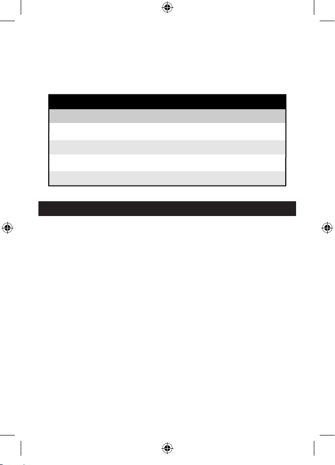
PROPER CHANNEL MAPPING
FUTABA and HITEC
JR and SPEKTRUM
CHANNEL 1 Aileron Throttle
CHANNEL 2 AileronElevator
CHANNEL 3 ElevatorThrottle
CHANNEL 4 RudderRudder
CHANNEL MAPPING
AnyLink includes two channel mapping sequences: one is for both
Futaba and Hitec radios, and another is used for both JR and
Spektrum radios. To manually set AnyLink’s channel mapping to
properly match the Tx being used:
1. Remove power from the Rx and servos in the model.
2. Center the Tx rudder trim.
3. Turn the Futaba or Hitec Tx power switch OFF. For JR or
Spektrum radios, only disconnect AnyLink’s “Power Plug” from the
Tx charge jack.
4. Move the Tx rudder (left) stick to the right-bottom or left-bottom
corner and HOLD IN THIS POSITION.
5. Turn the Futaba or Hitec Tx power switch ON. For JR or
Spektrum radios, re-connect the “Power Plug” to the Tx charge
jack. AnyLink’s LED will turn on.
6. Wait 5 seconds for AnyLink’s LED to flash three times ● ● ●
with tones to indicate the CHANNEL MAPPING mode has been
entered.
5
TACJ2000 AnyLink Mnl.indd 5TACJ2000 AnyLink Mnl.indd 5 10/26/2011 1:04:28 PM10/26/2011 1:04:28 PM
Page 6

7. Release the Tx rudder stick. If AnyLink was previously in Futaba/
Hitec mode, it should now have sounded two tones ● ● to indicate
it’s now in JR/Spektrum mode. If AnyLink was previously in JR/
Spektrum mode, it should now have sounded one tone ● to indicate
it’s now in Futaba/Hitec mode.
NOTE: If AnyLink’s Channel Mapping mode cannot be entered for
any reason, changing the servo connections at the receiver (standalone receivers only) to properly match the controls of the transmitter
can still allow AnyLink to function properly with your transmitter.
8. Re-apply power to the Rx and servos, and move the Tx sticks
to determine if controls in the model are properly matched. If NOT
properly matched, repeat steps 1 through 7 above to switch to
AnyLink’s alternate channel mapping sequence and re-check.
TACTIC RECEIVER
Install the Tactic Rx as explained in the instructions included with
the Rx/model. Follow these steps to bind AnyLink to the Tactic Rx:
IMPORTANT! Remove the propeller from the airplane
prior to checking the operation of AnyLink. Failure to do
so could result in personal injury if the motor unexpectedly
turns during setup.
1. Make sure the Tx throttle stick is in the MINIMUM power position.
2. Apply power to AnyLink and host transmitter.
3. Apply power to the Tactic Rx.
4. If the Rx LED flashes once and then stays on, the Rx is already
bound to AnyLink from a previous use. Otherwise, insert a small
diameter screwdriver in the hole on the Rx marked “BIND”. Press
and hold the pushbutton until the Rx LED glows red and then turns
off after about one second.
5. Release the “BIND” button. The LED will flash once and then
remain ON if bound successfully.
6. Test for proper communication with the Tx/AnyLink. If the system
doesn’t appear to have become properly bound, repeat steps 1-5.
6
TACJ2000 AnyLink Mnl.indd 6TACJ2000 AnyLink Mnl.indd 6 10/26/2011 1:04:28 PM10/26/2011 1:04:28 PM
Page 7

FAILSAFE FUNCTION: Many of Tactic’s fl ight receivers include a
failsafe function which can engage if the radio signal from AnyLink
somehow becomes interrupted. Refer to the instructions included
with your Tactic Rx to determine if it includes the failsafe function.
If radio signal is broken, the Rx failsafe feature can cause the
servos to automatically move either to a certain position, or hold
their last position to prevent the model from moving in an erratic
manner. Refer to the instructions included with the Tactic Rx to
determine which channels can enter a “hold” mode. The servo
connected to the throttle channel will move to a pre-set position.
The factory default is 0% (minimum) for throttle which should
cause motor/prop movement to stop if the Rx loses signal from the
Tx. The throttle servo’s failsafe position can be manually re-set to
any other position if desired, as follows:
IMPORTANT! Before manually resetting the failsafe,
make sure the Tx servo reversing settings are in the
correct position for the application.
1. Apply power to the Tx/AnyLink and Rx.
2a. If using an ESC, do NOT arm the ESC. Do NOT attempt to
adjust the throttle’s failsafe position if the ESC is armed.
2b. If using a gas or glow powered engine, do NOT attempt to
adjust the throttle’s failsafe position while the engine is operating.
3. Move the Tx throttle stick to the desired position for the throttle
control to move if the Rx goes to failsafe.
4. Press and hold the “BIND” button on the receiver, and the Rx’s
LED should blink twice. Release the BIND button, and the Rx
LED should turn on (stop fl ashing). The Tx and Rx should now be
bound, with the throttle failsafe in the new position as set above.
7
TACJ2000 AnyLink Mnl.indd 7TACJ2000 AnyLink Mnl.indd 7 10/26/2011 1:04:28 PM10/26/2011 1:04:28 PM
Page 8

SYSTEM CHECK AND OPERATION
Check the general operation of the system and all flight equipment
before attempting a flight.
WARNING! During all pre-flight preparations with the
aircraft on the ground, make sure the throttle stick
remains at the minimum position and do not stand the Tx upright
on the ground. Carefully lay the Tx on its back on the ground to
prevent it from falling over and possibly dislodging the throttle
stick from the low position which would create a safety hazard.
Make sure all devices are properly mounted inside the model,
and all wiring connections are solid to prevent them from easily
becoming dislodged during normal flight. It’s best to check the
system with the propeller removed from the aircraft.
Channel Mapping: If controls in the model do not function according
to the control inputs from the Tx, reset the system by repeating all
steps in the AnyLink Operation section on page 4. Proceed to the next
step once all channels are mapped properly.
Range Check: Determine the safe operating distance from the Tx to
the Rx. With the assistance of another person, place the aircraft on the
ground and walk 100 feet (30m) away from the model. Confi rm that
smooth, interference-free control of all surfaces exists.
Failsafe Check: If using the failsafe feature on a Tactic Rx, test for
proper operation as follows:
1. Prepare a way to quickly disconnect the battery/ESC connection if
power needs to be cut immediately.
2. Have an assistant hold the aircraft in place on a test stand, with
hands away from the motor.
3. Apply power to the system and test the motor and fl ight gear for
general operation.
4. Remove power from the Tx/AnyLink: turn off the power switch on
Futaba/Hitec transmitters, or for JR/Spektrum transmitters disconnect
AnyLink’s power plug from the Tx charge jack.
8
TACJ2000 AnyLink Mnl.indd 8TACJ2000 AnyLink Mnl.indd 8 10/26/2011 1:04:28 PM10/26/2011 1:04:28 PM
Page 9

5. Observe the model’s surfaces to ensure they move to the previously
set failsafe positions.
6. If failsafe operation is correct, re-connect power to the system as
explained earlier and prepare for fl ight. If the failsafe function does
not operate correctly, re-check the TACTIC RECEIVER and SYSTEM
CHECK AND OPERATION sections and re-try.
INACTIVITY ALARM AND POWER-DOWN PROCEDURES
Inactivity Alarm: If power is applied to AnyLink but the Tx sticks
are not moved for 4 minutes, AnyLink will sound tones to alert that
power is still ON and AnyLink is still transmitting a signal. Follow
the step below to remove power from AnyLink.
Turning off AnyLink: When finished flying and power has safely
been removed from the model, AnyLink needs to be turned off. For
Futaba and Hitec transmitters, simply turn the Tx power switch
OFF. For JR and Spektrum transmitters, disconnect AnyLink’s
power plug from the Tx charge jack. AnyLink’s LED will turn off.
IMPORTANT Special Note for JR and Spektrum Radios: Once
power has been removed from AnyLink as explained above, it’s
also necessary to disconnect AnyLink’s signal plug from the Tx
trainer/D.S.C. jack. Failure to do so will cause the logic circuit in
the radio to remain powered and discharge the battery in the Tx.
TACTIC ACCESSORIES
TACL0324 TR324 3-Channel 2.4GHz Receiver
TACL0624 TR624 6-Channel 2.4GHz Receiver
TACM0001 AnyLink SLT 2.4GHz Adapter Cable (Futaba Square)
TACM0002 AnyLink SLT 2.4GHz Adapter Cable (JR, Spektrum)
TACM0003 AnyLink SLT 2.4GHz Adapter Cable (Futaba/Hitec Round)
TACM0004 AnyLink SLT 2.4GHz Adapter Cable (Hitec Aurora)
9
TACJ2000 AnyLink Mnl.indd 9TACJ2000 AnyLink Mnl.indd 9 10/26/2011 1:04:28 PM10/26/2011 1:04:28 PM
Page 10

SPECIFICATIONS
Compatible Tx’s: Futaba, Hitec, JR, and Spektrum transmitters,
9 channels maximum
Compatible Rx’s: Tactic brand receivers
Frequencies: 2.403 – 2.480GHz
Modulation: FHSS spread Spektrum
Power indicator: LED with audible tones
Inactivity alarm:
audible tones after 4 minutes of Tx stick inactivity
Output power: < 0.1W
Case dimensions: 64 x 36 x 12mm (2.5 x 1.4 x 0.5")
Weight: 24g (0.85 oz.)
IMPORTANT WARNINGS AND PRECAUTIONS
● Do not allow water or moisture inside AnyLink, which could
cause failure or malfunction and poor control of aircraft and
pose a safety hazard.
● Do not operate R/C model aircraft near power lines, radio or cell
phone towers, roads or automobiles, buildings, or pedestrians.
● Do not operate R/C equipment if you are physically impaired as
it could pose a safety hazard to yourself or others in the area.
● Do not allow small children to operate/control model R/C
equipment without the supervision of an adult.
● Do not allow the Tx’s throttle stick to accidentally be moved
away from the “off” or minimum position while the model’s
engine/motor is moving.
● Do not store your radio equipment in extremely hot or cold
locations, in direct sunlight, or in locations with high humidity.
Store R/C equipment in cool and dry locations.
● Do not allow chemicals to come in contact with any parts of
AnyLink. Substances such as glow fuel, gasoline, CA glue, etc.
could permanently damage the case and electronic components.
● Always range check the radio system before use.
● Always make sure all Tx stick movements operate all servos
properly in the model. Check the proper operation of control
surfaces before and after starting the engine/motor.
10
TACJ2000 AnyLink Mnl.indd 10TACJ2000 AnyLink Mnl.indd 10 10/26/2011 1:04:29 PM10/26/2011 1:04:29 PM
Page 11

TROUBLESHOOTING
RANGE IS SHORT:
Interference – Check Rx installation and servo connections.
Low Tx or Rx battery –
Any Link case and/or antenna not oriented properly – Rotate AnyLink on
Tx, or re-direct position of the antenna.
Rx location – Relocate the Rx to a different position in the model for
better reception.
RUN TIME IS SHORT:
Low Tx battery – Replace or recharge the batteries.
POWER IS APPLIED TO ADAPTER BUT SERVOS DO NOT FUNCTION:
Tx or Rx batteries are low – Replace or recharge the batteries.
Rx switch off – Turn on the ESC or switch harness.
Swi tch harness or ESC is connected incorrectly – Check all connections
and the ESC instruction manual.
Rx not bound to AnyLink – Perform binding process again.
INTERFERENCE OR SERVOS GLITCHING:
Out of range – Operate the model more closely to the Tx.
AnyLink case not oriented properly – Rotate AnyLink on Tx.
Rx or ESC location – Relocate the Rx and/or ESC away from the engine,
motor, servos, or linkages for better reception.
WRONG CONTROL SURFACES MOVE IN RESPECT TO TX INPUT:
Repeat all steps in AnyLink Operation section on page __.
CONTROL SURFACE MOVES IN THE WRONG DIRECTION:
Reverse the position of the Tx’s reversing switch for the appropriate channel.
Replace the batteries or recharge as needed.
ONLY ONE SERVO GLITCHES:
Servo is bad – Replace or repair the servo.
11
TACJ2000 AnyLink Mnl.indd 11TACJ2000 AnyLink Mnl.indd 11 10/26/2011 1:04:29 PM10/26/2011 1:04:29 PM
Page 12

FCC STATEMENT
This device complies with part 15 of the FCC rules. Operation is
subject to the following two conditions. (1) This device may not
cause harmful interference. (2) This device must accept any
interference received, including interference that may cause
undesired operation.
FCC Rf Radiated Exposure Statement: The equipment complies
with FCC Rf radiation exposure limits set forth for an uncontrolled
environment. This equipment should be installed and operated
with a minimum distance of 20 centimeters between the radiator
and your body.
NOTE: THE MANUFACTURER IS NOT RESPONSIBLE FOR ANY
RADIO OR TV INTERFERENCE CAUSED BY UNAUTHORIZED
MODIFICATIONS TO THIS EQUIPMENT. SUCH MODIFICATIONS
COULD VOID THE USER’S AUTHORITY TO OPERATE THE
EQUIPMENT.
FCC ID: IYFTTX24GA
CE COMPLIANCE INFORMATION FOR THE EUROPEAN UNION
Instructions for Disposal of Waste Equipment by Private
Users in the European Union: This symbol on the product or its
packaging indicates this product must not be disposed of with other
household waste. Instead, it is the user’s responsibility to dispose of
their waste equipment by handing it over to a designated collection
point for the recycling of waste electrical and electronic equipment.
The separate collection and recycling of your waste equipment at
the time of disposal will help to conserve natural resources and
ensure that it is recycled in a manner that protects human health
and the environment. For more information about where you can
drop off your waste equipment for recycling, please contact your
local city offi ce, your household waste disposal service or location
where you purchased the product.
12
TACJ2000 AnyLink Mnl.indd 12TACJ2000 AnyLink Mnl.indd 12 10/26/2011 1:04:29 PM10/26/2011 1:04:29 PM
Page 13

Declaration of Conformity:
Product: Tactic AnyLink SLT 2.4GHz Radio Adapter Item number:
TACJ2000
Equipment class: 1
Tactic AnyLink SLT 2.4GHz Radio Adapter:
The objects of the declaration described here are in conformity with
the requirements of the specifi cations listed below, following the
provisions of the European 2006/95/EC Low Voltage Directive:
EN 60950-1:2006 Safety
The objects of the declaration described here are in conformity with
the requirements of the specifi cations listed below, following the
provisions of the European R&TTE directive 1995/5/EC:
ETSI EN 300 328 V1.7.1
Technical requirements for radio equipment
ETSI EN 301 489-1 V1.8.1, 301 489-17 V1.3.2
General EMC requirements for radio equipment
Tactic
c/o Hobbico®, Inc.
2904 Research Road
Champaign, IL USA 61826
CE COMPLIANCE INFORMATION FOR THE EUROPEAN UNION
The associated regulatory agencies of the following countries recognize the noted certifications
for this product as authorized for sale and use.
UK DE DK BG SE FI
EE LV LT PL CZ SK HU
RO SI AT IT ES PT IE
NL LU MT CY GR
13
TACJ2000 AnyLink Mnl.indd 13TACJ2000 AnyLink Mnl.indd 13 10/26/2011 1:04:29 PM10/26/2011 1:04:29 PM
Page 14

1-YEAR LIMITED WARRANTY – *U.S.A. AND CANADA ONLY
Tactic warrants this product to be free from defects in materials and
workmanship for a period of one (1) year from the date of purchase. During
that period, Tactic will, at its option, repair or replace without service charge
any product deemed defective due to those causes. You will be required to
provide proof of purchase (invoice or receipt). This warranty does not cover
damage caused by abuse, misuse, alteration or accident. If there is damage
stemming from these causes within the stated warranty period, Tactic will,
at its option, repair or replace it for a service charge not greater than 50%
of its then current retail list price. Be sure to include your daytime telephone
number in case we need to contact you about your repair. This warranty
gives you specific rights. You may have other rights, which vary from state
to state.
For service on your Tactic product, send it post paid and insured to:
HOBBY SERVICES
3002 N. Apollo Dr., Suite 1
Tel: (217) 398-0007 (9:00am - 5:00pm CST, M-F)
● This product is suitable only for people of 14 years and older.
This is not a toy!
● WARNING: CHOKING HAZARD - May contain small parts.
Keep away from children under 3 years. Please retain
packaging for future reference.
● No part of this manual may be reproduced in any form without
prior permission.
● The contents of this manual are subject to change without
prior notice.
● Tactic is not responsible for the use of this product.
Champaign, IL 61822
E-mail: hobbyservices@hobbico.com
14
TACJ2000 AnyLink Mnl.indd 14TACJ2000 AnyLink Mnl.indd 14 10/26/2011 1:04:29 PM10/26/2011 1:04:29 PM
Page 15

AnyLink Transmitter
Compatibility Chart
4YF, 4YBF, 6J,
6EX, 7C, 9C,
8FG, 10C, 12FG
Futaba
®
Requires optional adapter cable
*
TACM0003
TACM0004
4VF, 5U, 6DA, 6H,
6A, 6YG, 6YF,
7NFK, 8U, 9Z
Prism 7 & 7X;
Aurora 9
Focus 4 & 6;
Flash 4sx;
Hitec
®
Flash 5 & 5sx;
Eclipse7,
Optic 5 & 6;
Laser 4 & 6;
Neon
10X, Quattro
XP6102,
XF421, XP783,
J.R.
®
X9503, X9303,
XP8103, X388S
®
Spektrum
Tower Hobbies
Transmitters not listed above may or may not be compatible with AnyLink.
*
DX6, DX6i, DX7
®
6XM 4FM, 6FM
Check Tx-Ready.com for updated compatibility chart.
15
TACJ2000 AnyLink Mnl.indd 15TACJ2000 AnyLink Mnl.indd 15 10/26/2011 1:04:29 PM10/26/2011 1:04:29 PM
Page 16

tacticrc.com
Tx-Ready.com
© 2011 Hobbico®, Inc. Made in China TACJ2000MNL
TACJ2000 AnyLink Mnl.indd 16TACJ2000 AnyLink Mnl.indd 16 10/26/2011 1:04:29 PM10/26/2011 1:04:29 PM
 Loading...