

Page 1
INSTRUCTION MANUAL
WARNING! THIS IS NOT A TOY!
Assembly and operation of this aircraft must be done by or under
the direct supervision of a responsible adult. If not handled
correctly, this model is capable of inflicting serious bodily harm.
It is your responsibility and yours alone to assemble this model
correctly, properly install all R/C components and to test and
operate it in a safe and responsible manner.
Entire Contents © Copyright 1998 HCAA1010 V20
ARF1P01
Page 2
Stock # Description Qty
Al UM007P Aluminum Channel 1
ARF1F01 Plastic Fuselage Tube 1
ARF1P01 Instruction Book 1
ARF1R05 1/64 Plywood Fin
ARF1W02 Plastic Wing Protector 1
EM20481 Engine Mount Left 1
EM2048R Engine Mount Right 1
FWING02L Molded Foam Wing Left 1
FW1NG02R Molded Foam Wing Right 1
L-6U Landing Gear 1
NYLON87 CA Hinge Strip
PLTB009
PLTB011 24" Grey Outer Pushrod 2
PLTB012
PLTB013
WIRES 16 Threaded Link Rod 5
ARF1A01 Subpack
ARF1R04 1/4 x 1/2 x 13
ARF1S01 1/4 Balsa
ARF1S02 1/4 Balsa Stabili/er 1
ARF1S03 1/4 Balsa Elevator 1
ARF1W01 1/8 Plywood
ARF1A02 Subpack
ARF1R01 1/4 Balsa Fin Front 1
Loose in Box
Doubler 1
24"
White Inner
11-3/4"
11-3/4"
Inner Pushrod 1
Outer
Pushrod
Stabilizer & Wing Parts
Balsa Fin Doubler 1
Stabili/er Front 1
Wing Joiner 1
Fin & Rudder Parts
1
Pushrod
1
PARTS LIST
Stock # Description Qty
ARF1R02 1/4 Balsa Fin 1
ARF1R03 1/4 Balsa Rudder 1
ARF1A03 Subpack
ARF1F03 9mm Plywood
ARF1F04 1/4 Plywood Firewall 1
ARF1F05 1/4 Ply
ARF1F06 Pushrod Holder
ARF1S04 1/16 Plywood
2
DOWEL030 1/4 x3 1/2 Dowel 4
ARF2A04 Subpack
ARF2W03 3/8 Tapered TE 2
ARF2W04 3/8 Tapered Aileron 2
ARF2A05 Subpack
ARF2W05 Grooved Center TE 2
ARF2W06 TE Support 2
ARF2W08 Servo Rails 2
NYLON20 Non threaded Swivel 2
NYLON21
WBNT110L Aileron Torque Rod Left 1
WBNT110R Aileron Torque Rod Right 1
Small Wood Parts
Firewall Doubler 1
Landing Gear Supports 2
(3/4 x 1
/2 x 1 ) 1
Stabili/er Doubler 1
Long Aileron Parts
Small Aileron Parts
Swivel
Clevis
Stock # Description Qty
ARF1MOI Subpack Hardware
(Contains the Following)
NUTS001 4 40 Blind Nut 6
NUTS002 4 40 Hex Nut 2
NUTS010 6 32 Hex Nut 4
NUTS014 8 32 Hex Nut 2
NYLON03 Nylon Control Horn 2
NYLON 17 Nylon Clevis 3
NYLON52 5 1/2 Nylon Tie 2
SCRW002 2 56 x 5/8 Bolt 4
SCRW010 #4x5/8
Sheet Metal Screw 4
SCRW024 #2 x 3/8
Sheet Metal Screw 8
SCRW052 4 40 x 5/8 Bolt 4
SCRW053 8 32 x I /2 Bolt 2
SCRW055 6 32 x 1 1/2
SH Cap Screw 2
SCRW104 4 40 x 1 1/4
Machine Screw 4
WBNT146 Prebent Tailskid 1
WIRES20 1 Threaded Link Rod 3
WSHR002 #4 Lock Washer 2
WSHR004 #6 Flat Washer 4
WSHR005 #4 Flat Washer 4
WSHR010 #8 Lock Washer 2
WSHR011 #8 Flat Washer 1
2
2
Page 3

TABLE OF CONTENTS
Parts List.................................................2
Introduction ............................................3
Additional Item Description .....................3
Additional Item Check List.......................4
Tools or Supplies Needed.........................5
Fin & Rudder Construction......................5
Installing CA Hinges ................................6
Stabilizer & Elevator Construction........... 8
Wing Assembly ......................................10
Covering................................................ 14
Installing the Hinges..............................14
Attaching the Control Horns.................. 15
Fuselage Construction........................... 15
Final Assembly ......................................22
Balancing..............................................23
Getting Ready for Flying ........................23
Flying....................................................23
Repairing .................................Back Cover
INTRODUCTION
Congratulations on your purchase of the
HOBBICO STURDY BIRDY II. THE FIRST
REAL SUPER TRAINER. You now own the
BEST FLYING durable trainer available. By
following these instructions as you assemble
the model, you will have a great flying plane.
It will not only teach you how to fly, but will
stick by you while you learn, no matter how
long that may take!
The first thing you should do after reading
this paragraph is check the parts in this kit
against the parts list to make sure everything
is here.
We strongly recommend that you join the
Academy of Model Aeronautics. Being an AMA
member entitles you to liability insurance and
puts you in touch with your local flying
club. It also includes a subscription to MODEL
AVIATION magazine, which has a monthly
listing of the latest news in model aviation.
Insurance is the most important advantage of
the AMA membership. If your model hits
someone or something, you are liable for any
damage it causes.
You can contact the national Academy of
Model Aeronautics, which has more than
2,500 chartered clubs across the country.
Through any one of them, instructor training
programs and insured newcomer training are
available.
Contact the AMA at the address or toll-free
phone number below.
Academy of Model Aeronautics
5151 East Memorial Drive
Muncie, IN 47302-9252
Tele. (800) 435-9262
Fax (765) 741-0057
Web Site:
HTTP:
//WWW.
We also recommend that you join your local
flying club. There you will find people who
can help you learn to fly and teach you the
safe ways of handling your aircraft.
MODELAIRCRAFT.
ORG
ADDITIONAL ITEMS
DESCRIPTION
Here is a description of some of the items you
will need to assemble your STURDY BIRDY II
GLUES
CA (Cyanoacrylate) glues will be used to glue
the wood parts together because they are
strong and very fast curing. Do not use CA
glues for the wing construction because most
CA glues will attack and dissolve the foam
wing. They come in different viscosities. Thin
CA glue can be used when gluing parts with
a good, tight joint. When using thin CA,
3
Page 4

assemble the parts first and then add the
glue. It will penetrate the joint and cure in a
couple of seconds. Thick and medium CAs
are applied to the parts before they are
assembled since the glue will not cure for
20-30 seconds. This longer curing time gives
you more time to get the parts assembled
accurately before the glue cures. The thicker
consistency also
CA accelerator spray can be very handy
for speeding up the curing process of the
thick CAs.
Epoxy is a two-part adhesive that has to be
mixed before it will cure. We will use epoxy
glue for the wing assembly since it takes a
little longer to cure and does not attack the
foam. Epoxies come in several different types
with many different curing times. You should
buy some epoxy with a 30-minute curing
time for use here.
ENGINE
The STURDY BIRDY II is designed to fly with
a standard .20 size 2-stroke engine. The OS
.20 FP is a great, inexpensive engine that
provides plenty of power. This combination is
ideal for the average beginner. A .25 - .30 size
engine can be used if you would like snappier
performance, especially at higher elevations
where the air is thinner. We recommend that
you do not use an engine larger than a .30
as the additional weight makes the plane
more difficult to fly at low speeds. The engine
mount provided with the STURDY BIRDY II
will fit most .20 - .30 engines.
helps
fill
poor fitting
joints.
FUEL TANK
The STURDY BIRDY III was designed to hold
a 6 oz. square tank. A 4 oz. tank will also
work but will give you shorter flight times.
COVERING
Although not absolutely necessary, the "tail
feathers" and the wing should both be
covered with a "low heat" type iron on
covering. EconoKote^ and Black Baron® Film
are both good coverings to use on your
STURDY BIRDY II. The covering will not
only make your plane look nicer, but it will
also add strength and make it last longer.
CHECK LIST OF ADDITIONAL
ITEMS YOU WILL NEED
D .20 -.30 2-Stroke Engine
D 4 Channel Radio
D 4 Standard Size Servos
D Several 9 X 4 or 9 X 6 Propellers
D 2-1/2" Wheels (2)
D 6 oz. Square Fuel Tank
D Box #64 Rubber Bands
D Thin CA (Cyanoacrylate) Glue loz.
D Thick CA (Cyanoacrylate) Glue loz.
D 30-Minute Epoxy 4oz.
D Roll of Low Heat Iron-On Covering
D Foam Rubber for Cushioning Receiver
D 12" Standard Size Fuel Tubing
D 3/4" Wide Nylon Reinforced Tape
RADIO
The STURDY BIRDY II requires 4 channels to
fly. The radio system you purchase should
have standard size servos so they will fit into
the fuselage channel. Mini or micro servos will
also work but they will require some
modifications to fit properly. Large servos will
not work in the STURDY BIRDY II.
Questions or Problems?
Contact us at:
4
Hobby Services
Attn: Service Department
1610 Interstate Drive
Champaign, IL 61821-1067
(217)
398-8970
Page 5
TOOLS & SUPPLIES NEEDED
D Sealing Iron D Razor Saw
D Hobby Knife D Pliers
D Screwdrivers D T-Pins
D Hammer D Wax paper
D Sanding Block or Bar Sander
D Nylon Reinforced Strapping Tape
D Hand or Electric Drill
D Drill Bits (3/32", 1/8". 3/16", 5/32", 7/32")
FIN & RUDDER
CONSTRUCTION
glue has cured, flip the pieces over and add a
little glue to the other side.
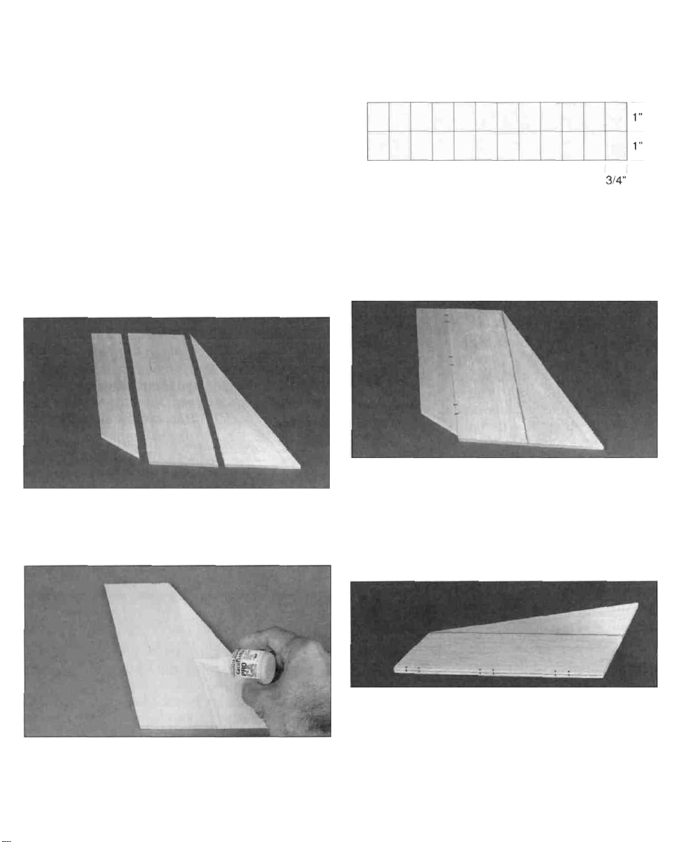
D 3. As shown in the above sketch, cut 18
hinges from the supplied 2" x 9" composite
hinge material. You will need five hinges for
the elevator and three for the rudder. Each
aileron gets three hinges.
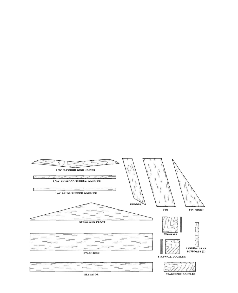
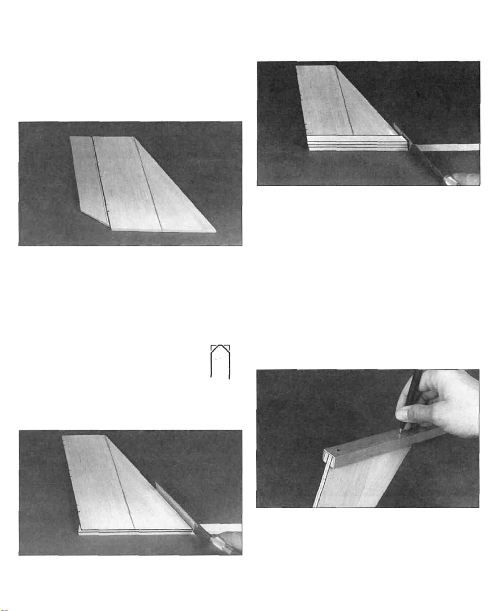
D 1. The fin is made up of the three pieces
shown above. Locate these three pieces and
lay them out.
D 2. Glue the front part of the fin to the main
part using thin CA. Assemble the two parts
and check to make sure they fit properly. Then
apply a line of CA along the joint. When the
D 4. Lay the rudder in place against the
trailing edge of the fin. Using a hinge as a
template, mark the hinge locations. They are
spaced out so that the outer hinges are
approximately 1" from the ends of the rudder
and the middle hinge is in the center.
D 5. Draw a line down the middle of the
trailing edge of the fin and also down the
middle of the leading edge of the rudder. A
sheet of wood (or anything) 1/8" thick laid
down next to the piece makes it easy to do
this. Transfer the hinge locating marks from
the side to the edges as shown above
5
Page 6
Note: Before proceeding to hinge the rudder.
read completely through the section on
Installing CA Hinges. Do not use any glue
until after the tail surfaces are covered.
INSTALLING CA HINGES
The hinge material supplied in this kit
consists of a 3-layer lamination of mylar and
polyester. It is specially made for the purpose
of hinging model airplane control surfaces.
Properly installed, this type of hinge provides
the best combination of strength, durability
and ease of installation. We trust even our best
show models to these hinges, but it is
essential to install them correctly. Please
read the following instructions and follow
them carefully to obtain the best results.
These instructions may be used to effectively
install any of the various brands of CA hinges.
The most common mistake made by modelers
when installing this type of hinge is not
applying a sufficient amount of glue to fully
secure the hinge over its entire surface area;
or, the hinge slots are very tight, restricting
the flow of CA to the back of the hinges. This
results in hinges that are only "tack glued"
approximately 1/8" to 1/4" into the hinge
slots. The following technique has been
developed to help ensure thorough and
secure gluing.
few times to provide more clearance (it is
really the back edge of the blade that does
the work here in widening the slot).
CAUTION: Do not drill this hole when
hinging a foam wing, as this hole would allow
too much CA to penetrate and cause damage
to the foam.
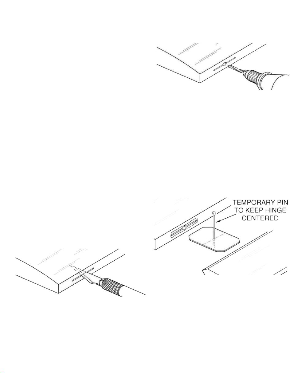
B. Drill a 3/32" hole, 1/2" deep. in the
center of the hinge slot. If you use a Dremel
MultiPro for this task, it will result in a
cleaner hole than if you use a slower speed
power or hand drill. Drilling the hole will twist
some of the wood fibers into the slot, making it
difficult to insert the hinge, so you should
reinsert the knife blade, working it back and
forth a few times to clean out the slot.
A. Cut the hinge slot using a # 11 blade in a
standard #1 knife handle. The slots should
be about 3/4" deep. The CA hinges provided
have a thickness that fits this type of slot
very well. Cut off the corners of the hinge at a
45 degree angle and trial fit the hinge into the
slot. If the hinge does not slide in easily, work
the knife blade back and forth in the slot a
C. Insert the hinges and install the control
surface. Verify the left-right positioning of the
control surface and close up the hinge gap to
1/32" or less. It is best to leave a very slight
hinge gap, rather than closing it up tight, to
help prevent the CA from wicking along the
hinge line. If you have cut your hinge slots too
deep, the hinges may slide in too far. leaving
only a small portion of the hinge in the control
surface. To avoid this, you may insert a small
6
Page 7
pin through the center of each hinge, before
installing. This pin will keep the hinge
centered while installing the control surface.
Note: When hinging the ailerons, which use
torque rods, use a toothpick to force epoxy
down the hole drilled for the torque rod. In
the case of the rudder, be sure not to let glue
get into the bearing tube.
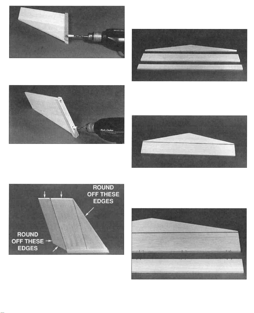
D 6. Trial fit the fin and rudder together using
the hinges to check for proper alignment.
Do Not glue the hinges in place yet! Sand the
rudder and/or fin so they match each other at
the top.
D 7. Remove the hinges from the
rudder and bevel the leading edge
with your sanding block as shown in
the sketch. This is to allow the
rudder to swing either direction once
EDGE VIEW
the hinges are glued in place.
above. Use a razor saw to cut the excess off at
the leading and trailing edges.
D 9. Check the fit of the fin assembly into
the aluminum channel. It will most likely be
a little loose and we want a nice, tight fit. Add
a strip of the 1/64" plywood doubler to ONE
side of the fin. Glue it to the balsa doubler.
Check the fit again and if it is still a little
loose, add a plywood doubler to the other
side. If necessary, you can sand the plywood
slightly to help the assembly fit. Also, you
can have the covering material continue
down over the doublers if you need the
additional thickness.
D 8. Add the 1/4" x 1/2" balsa doubler to
each side of the fin as shown in the photo
D 10. Position the fin assembly in the channel
with the trailing edge of the fin even with the
end of the channel. Press it in place. Mark the
location of the stabilizer bolt holes on the
bottom of the fin and then remove the fin from
the channel.
7
Page 8
D 11. Wrap a piece of masking tape around a
7/32" drill bit about 1/2" from the end of
the
bit.
D 12. Drill two holes in the bottom of the fin
assembly to make a space for the stabilizer
bolts. Be careful not to drill any deeper than
the masking tape or you may drill through the
side of the fin.
STABILIZER
& ELEVATOR
CONSTRUCTION
D 14. The stabilizer and elevator are
assembled from these three main pieces.
Locate these and let's get started.
D 15. Glue the front of the stabilizer to the
back using thin CA just as you did for the fin
in step #2.
D 13. Use a sanding block to round the edges
of the fin/rudder assembly as shown above.
Give the sides a quick sanding with some fine
sandpaper to get them ready for the covering.
This completes the basic assembly of the fin
and rudder. The hinges and control horn will
be installed after everything is covered.
D 16. Mark the hinge locations using the
same technique you used in step #4. There are
five hinges used here. The outer hinges are
8
Page 9

approximately 1" from the edge. The middle
hinge is in the center and the other two hinges
are centered between the outer hinges and the
middle hinge. These hinge locations are not
critical, but proper placement makes it easier
to find the slots after the parts are covered.
Cut the slots for the hinges and test fit the
stabilizer and the elevator together to check for
proper alignment between the two parts.
D 17. Use some thick CA to glue the 1/16"
plywood doubler in place on the stabilizer. This
side is now the bottom of the stabilizer. Use
a ruler to get this piece centered as close as
possible. Use a drafting triangle or carpenter's
square to draw a line perpendicular to the
stabilizer trailing edge and through the center of
the stabilizer to the point where the leading
edges meet.
Sight down the bottom of the channel and line
the stabilizer up with the channel (using the
line you just drew). When you are satisfied with
the alignment, draw a line down both sides of
the channel on the top of the stabilizer.
D 19. Remove the pencil and rubber band.
With the stabilizer centered over the lines, drill
two 1/8" holes through the stabilizer using the
holes in the channel as a guide. The trailing
edge of the stabilizer should be slightly past
the end of the channel.
D 20. Use a sanding block with some fine
sandpaper to round off the leading edges,
trailing edge and the tips as you did for the
fin and rudder. Also sand the top and bottom
surfaces smooth. This completes the basic
assembly of the stabilizer and elevator. The
control horn and the hinges will be installed
after the tail is covered.
D 18. Use a pencil and a rubber band to hold
the stabilizer in place as shown in the photo.
9
Page 10

WING ASSEMBLY
INSTALL THE AILERONS
Balsa SUB TE 26-1/2" Long
D 1. Locate the two balsa 15/32" x 3/8 x
26-1/2" Sub Trailing Edge pieces (Sub TE).
Trial fit the Sub TE against the trailing edge of
each wing half. The Sub TE should be oriented
as shown in the sketch with the 90-degree
corners along the bottom of the wing. Epoxy
the Sub TE to the trailing edge of each wing
half. Pins or tape can be used to help hold the
Sub TE in place while the glue cures.
Use the sketch to help you determine which
side is the top and mark the top side of each
piece. Make another mark 7/16" from the
"inboard" end of each piece. Notch each piece
to make a slot for the torque rod.
Note: The threaded portion of each torque rod
should stick out the top of each wing. Also
there will be a "right" and a "left" center trailing
edge piece so don't make two exactly alike.
Balsa CENTER TE 3-7/8 " Long
D 2. Locate the two balsa 3/8" x 1-1/4" x
3-7/8" tapered center trailing edge pieces.
D 3. Use 150-220 grit sandpaper to roughen
the outer surface of the torque rod bearing.
Slide the bearing toward the threaded end of
the torque rod and put a small amount of
petroleum jelly around the ends of the
bearing tube to prevent epoxy from seeping
in. Spread some epoxy in the slot and on the
leading edge of the center trailing edge
pieces. Do not apply any epoxy within 1/4" of
the notch or you may glue the torque rod.
Insert the torque rods into the slots with the
threaded portions sticking out through the
notches. Position the center trailing edges
against the wing sub trailing edge. Align the
center trailing edges and pin or tape them in
place while the glue cures.
10
Page 11

D 4. Epoxy the two 11/32" x 2" x 1-5/8"
Tapered TE Supports to the inboard bottom of
each center trailing edge as shown in the photo.
D 5. Use a sanding block with 150-grit
sandpaper to sand the inner ends of the sub
trailing edge. center trailing edge and the
tapered trailing edge to match the angle of
the foam wing end. Be careful not to change
the angle of the foam wing.
AILERON
22-1/2" Long
ARF2W04
D 6. Hold the 3/8" x 1-1/4" x 22-1/4" Ailerons
in place against the sub trailing edge and under
the torque rods. Mark the location where the
torque rods will enter the ailerons. Drill a 3/32"
hole in each aileron to accept the torque rods.
D 7. Cut a groove in the leading edge of the
aileron to allow clearance for the torque rods.
Trial fit the ailerons in place and cut as
necessary until they fit.
D 8. Draw an accurate centerline along the
leading edge of the aileron and cut three
hinge slots in each aileron. The hinge slots
should be approximately 1-1/2", 10" and 18"
from the wing tip. Place the ailerons against
the sub trailing edge and mark the hinge
locations on the wing. Draw a center line
down the sub trailing edge and cut the hinge
slots to match the ailerons.
D 9. Using a sanding block, sand the leading
edge of each aileron to a "V" shape.
11
Page 12

D 10. Insert the hinges into the slots and
trial fit the ailerons in place on the wing. Do
not glue the hinges until after you have
covered the wing. Sand the outboard edge of
the sub trailing edges and the ailerons to
match the foam wing tips.
JOIN THE WING PANELS
D 1. Use a sanding block with some fine grit
sandpaper (240 - 320 grit) to remove the little
nubs and any mold lines left on the wing
from the molding process.
D 3. Lay some wax paper down on the work
surface and mix up one ounce of epoxy.
Spread the epoxy throughout the slot and on
the root (middle end) of the other wing panel.
Slide the two wing panels together and line
them up as close as possible. Use several
T-pins and masking tape to help hold them in
alignment. Flip the wing assembly over so that
the bottom of the wings are facing up and
make sure that the joiner is seated properly in
the slot. Wipe off any excess epoxy before it
starts to cure. It is important that the wings
are joined with both panels being accurately
aligned with each other.
D 4. Allow the epoxy from the last step to
fully cure.
D 2. Test fit the 1/8" plywood dihedral joiner
in the slots in the wing to make sure it fits
nicely. Mix up about 1/2 oz. of epoxy and
spread it throughout the slot in one wing
panel. With the wing panel upside down,
insert the joiner in place and squeeze out all
the excess epoxy so that the joiner is flush
with the bottom of the wing (which is facing
up). Try to use enough epoxy so that the slot
is completely full and level with the surface of
the wing.
Note: The tape used in this step is 3/4" wide
nylon filament reinforcing tape. This is
self-adhesive tape with nylon filaments
running the length of the tape. It is also
referred to as "nylon filament strapping tape,"
or "nylon reinforced packaging tape." You can
obtain it at any store that sells stationery and
packaging materials or at most hardware
stores. Be sure to use 3/4" wide tape.
Narrower tape will not provide the wing with
12
Page 13

proper reinforcement. Make sure the tape is
applied with no wrinkles and that the strips
are straight and parallel from wingtip to
wingtip. If this tape is not applied, if it is
applied incorrectly or if a different type of
tape is applied, we cannot be responsible
for any wing failure that may occur.
D 5. Place the wing upside down on the edge
of a table so that only 1/2 of the wing (from
one wing tip to the center joint) is resting on
the table. Starting at the wing tip that is
resting on the table, lay a strip of nylon-
reinforced strapping tape down so that it
crosses over the center joint directly over the
wing joiner.
INSTALL THE WING PROTECTOR
D 1. Use a sharp hobby knife or a Dremel®
Tool with a tapered cutting bit to trim out the
servo and torque rod cut-outs in the Plastic
Wing Protector. There are scribe lines on the
bottom surface of the protector to help guide
you. Trial fit the aileron servo in place and
trim as necessary to make it fit properly. Use
scissors or your hobby knife to trim the
outside edges of the wing protector along the
remaining scribe lines.
D 2. Place the wing protector on the center of
the wing so the torque rods fit through their
holes. Draw a line on the wing around the
servo cutout. Remove the protector and carve
out a hole in the foam wing to fit your servo.
Carve out an extra 1/4" square groove in front
and behind the servo cut-out for the servo
rails. Drill a 1/2" diameter hole for the servo
wires down through the front edge of the servo
cutout. Be careful not to cut the plywood wing
joiner when performing these operations.
Press the tape firmly onto the wing and down
into the fillet (where the bottom of the wing
meets the mounting platform) and then flip
the wing around and continue the strip of
tape out to the other wing tip. Apply two
more strips of tape between this strip and the
trailing edge of the wing. The fourth strip
should be added between the first strip and
the leading edge of the wing. The previous
photo shows where the strips should be
located. Try to get this tape stuck down
as tightly as possible because it adds a
tremendous amount of strength to the wing
when properly applied. Make sure you do not
change the washout (twist) or dihedral
(V-shape) of the wing when applying the tape
strips. If you are planning on doing some
aerobatics or combat with your STURDY
BIRDY
tape on the top surface of the wing.
II,
you should
also
put
three
strips
of
D 3. Glue the 3/16"x l/4"x 1-1/4" Basswood
Servo Rails in place along the front and back
edges of the servo cut-out. Put the aileron
servo in place and mark on the plastic
protector where the servo mounting screws
should be. Drill 1/1 6" diameter holes on the
marks you just made and mount the servo
using the screws provided with your radio.
D 4. Trial fit the wing protector assembly on
the wing and enlarge the cutouts in the foam
13
Page 14

wing if necessary to make the protector lie
flat against the wing. When satisfied with
the fit, remove the servo. Use coarse
sandpaper to roughen the bottom of the wing
protector so the glue will hold better. Use
epoxy to glue the protector in place.
D 5. Trial fit the ailerons for this step. Mount
the aileron servo with the screws provided in
the radio system and assemble the pushrods
as shown in the sketch above. Attach the
pushrods to the torque rods by screwing the
Aileron Clevis Connector onto the threaded
portion of the torque rod. Use a pair of needle
nose pliers to make the Z-bends and attach
them to the servo horn. Turn on your radio.
plug in your aileron servo and adjust the
centering of the servo horn until it is
centered and the right aileron moves up
when you move the transmitter stick to the
right. Adjust the nylon clevis until each
aileron is in a neutral position when the
transmitter sticks and trims are centered.
Also adjust the position of the nylon clevis
connector on the torque rod to achieve 7/16"
of up and down movement.
are also going to cover the wing, which will
help it look nicer longer (and add a
small amount of strength), you can save a
little money by buying only one roll of low
temperature covering (EconoKote, Black
Baron Film, etc.) and using it for both the
wing and the tail surfaces. Otherwise you can
use any type of covering for the tail surfaces,
but remember to use a low heat covering for
the wing. A few stripes or your AMA number
can really add to the looks of your STURDY
BIRDY II.
D 2. Follow the instructions that come with
the covering and cover the tail surfaces at
this time. It is a good idea to cover the bottom
surfaces first to get familiar with the covering
since these surfaces will normally not be
seen. When covering the wing, cover right
over the tape and plastic wing protector. Try
to use as little heat as possible.
ATTACHING THE CONTROL HORNS
COVERING
D 1. The tail surfaces (fin, rudder, stabilizer
and elevator) should be covered with one of
the iron-on coverings to help protect them
from becoming fuel soaked and ruined. If you
D 1. Position the nylon control horn on the
left side of the rudder about 1" up from the
bottom with the four holes lined up with the
leading edge. Use a drop of Thin CA to tack
glue the horn in place.
14
Page 15

D 2. Drill two 3/32" holes through the
rudder using the control horn as a guide.
D 3. Secure the horn to the rudder with two
2-56 x 5/8" machine screws. The screws
should thread into the nylon "nut plate" on
the opposite side of the rudder. Although not
necessary, you may use some wire cutters or
an abrasive cutoff wheel to cut the screws off
even with the plate.
D 4. The other control horn should be
installed on the top surface of the elevator
about 1" to the right of the centerline. Follow
the same procedure for installing this
control horn.
INSTALLING THE HINGES
D 1. After covering the tail surfaces and the
wing, the hinges can be installed. Use your
hobby knife to find the slots you cut earlier
and make slits in the covering so you can
push the hinges into place and trial fit the
pieces together again. (Refer to the CA hinge
section on page 6.)
D 2. The control surfaces will take some
abuse in the learning-to-fly process, so you
must securely glue the hinges in place. Use
four to six drops of CA on each side of the
hinge to secure them. Try to get the surfaces
as close together as possible, but work the
control surfaces back and forth while the
glue is curing to make sure they work freely
without binding. Also, be careful not to glue
the two surfaces together.
FUSELAGE CONSTRUCTION
D 1. Locate the 3/8" plywood
firewall doubler and round
off the corners with a
sanding block. Test fit the
doubler into the front of the
plastic fuselage tube as
shown above. The firewall
doubler should fit into the
fuselage with a snug but not
tight fit. The front of the
fuselage is cut at a slight
angle so the firewall and thus
the engine will point down slightly. Because
of this angle the top and bottom edges of the
firewall doubler are also cut at a slight angle.
Make sure you install the firewall doubler so
all of its sides match up nicely with the sides
of the fuselage as shown in the sketch.
15
FIREWALL
DOUBLER
Page 16

D 2. The 3/8" plywood firewall doubler is
now glued to the 1/4" plywood firewall front.
Use either Thick CA or epoxy and make sure
that the front of the firewall doubler is
centered on the back of the firewall. Wipe
away all excess glue that squeezes out.
Tick marks for alignment
Determine where the mount should be
installed on the firewall. Use the template in
the left column to make it easy to locate the
mounting holes. Photocopy or cut out the
template and tape it in place on the firewall.
Poke a T-pin though the template to
accurately mark the bolt locations on the
firewall. Drill a 1/8" diameter hole at the four
pin holes and install the mount using 4-40
bolts, #4 flat washers and 4-40 blind nuts.
The length of the bolts will be determined by
the thickness of the firewall. A 1/4" firewall
will usually require 7/8" long bolts. Do not
tighten the bolts all the way yet.
D 3. Cut or break the "spreader bar" off each
mount half. Carefully trim any extra plastic off
each mount half left by the spreader bar. The
surfaces where the spreader bars were attached
need to be very smooth to allow the mount
halves to fit together. Also trim the flashing off
any other rough edges. Snap the two mount
halves together as shown in the sketch.
Slide the mount halves apart until the engine
mounting lugs will sit flat on the beams.
Adjust the mount until the firewall centerline
(or offset line) is centered between the "tick"
marks on the mount. Tighten the 4-40 bolts
to hold the mount halves in position.
Determine how far forward the engine should
be positioned on the beams and mark where
to drill the mounting holes. Remove the
engine and drill a 3/32" hole at each mark.
Put a drop of oil in each hole and install the
engine using the #4 x 5/8" screws provided.
If you prefer to use 4-40 machine screws (not
included) to install your engine, just tap the
holes you drilled with a 4-40 tap.
With the engine installed on the mount, mark
the location for the throttle pushrod and fuel
lines. Remove the engine and mount. Drill a
3/16" hole in the firewall for the throttle and
two 7/32" holes for the fuel and vent lines.
16
Page 17

D 4. Use a small piece of coarse sandpaper
to scuff up the inner floor of the aluminum
channel in the area around the front 11/64"
bolt hole.
end of the channel. Square battery packs fit
nicely but most flat
packs
will
also
fit.
Just
tape them flat onto the channel. The battery
should protrude approximately 1/8" past the
end of the channel to keep the fuel tank from
rubbing against the end of the channel.
D 5. Insert one of the 8-32 x 1/2" machine
screws into the hole so that it sticks out the
bottom of the channel and glue it in place
with plenty of thick C A or epoxy. This screw
will be covered by the battery pack,
prohibiting a screwdriver from being used to
keep it from turning. Glue it securely, but be
careful not to get any glue on the threads.
D 6. Use some nylon reinforced strapping tape
to securely hold the battery pack on the front
D 7. The servos are "press fit" into the
aluminum channel and then held in place with
nylon strapping tape. Standard size servos
should fit very nicely and smaller servos can be
held in place by using a piece of wood to fill the
space between the servo sides and the channel.
Large servos will not work in the STURDY
BIRDY II. The servos should be placed as far
forward in the channel as possible and right
next to each other, but do not overlap the servo
mounting lugs. The front two servos should be
mounted with their servo output shafts
towards the back of the plane and the back
servo should have its output shaft towards the
front of the plane. The servo wires should be
routed out to the side of the servo without
going under any servos. Wrap two layers of
nylon strapping tape all the way around each
servo and the aluminum channel to hold it in
place. Hook up the entire radio system and
turn it on (see the instructions included with
your radio). Adjust the transmitter trims so
they are in the middle of their slots.
17
Page 18

Remove the screws that hold the servo horns
in place and adjust the horns so that they are
perpendicular to the servo. This will be their
neutral position. It is a good idea to use single
arm servo horns rather than the round horns
most servos come with. The sketch shows how
to cut a horn for use here. Reinstall the screws
that hold the horns in place.
D 8. Attach the stabilizer/elevator to the
back of the channel using two 4-40 x 5/8"
machine screws, two #4 flat washers, two
4-40 lock washers and two 4-40 nuts.
D 9. Press the fin/rudder into the channel
with the back edge of the fin even with the
back edge of the channel as shown in
the photo.
D 10. Assemble the two pushrods by
screwing a 1" threaded rod into one end of
each inner pushrod and then screwing a
nylon clevis onto each threaded rod. The rod
should thread into both the pushrod and the
clevis at least 13 turns.
The sketch shows how the pieces are
installed. The prebent tail skid is held in
place by the rear screw.
D 11. Attach the two long pushrods to the
two rear servos as shown in the photo. Slide
18
Page 19

the outer pushrod tubes over the inner
pushrod until they are about 1/2" from the
servo end of the inner pushrod.
D 12. Press the balsa pushrod holder into
the channel about 6" in front of the fin and
secure the pushrods to it with the nylon tie
wrap. It is a good idea to seal the balsa
pushrod holder with a light coat of epoxy that
will also help hold it in place.
Note: The rudder pushrod goes to the left side
of the fin. The elevator pushrod goes to the
right side (as viewed from the back).
D 14. Install the link rods in the 2nd hole
from the outer end of each control horn. With
the control surfaces and the servo horns in
their neutral positions, cut the inner pushrod
so the link rod will thread into the inner
pushrod approximately 2/3 of the way.
Install the link rods into the inner pushrods
and adjust so that the control surfaces are at
neutral positions.
D 15. Wrap the receiver in at least 1/4" thick
foam rubber to protect it from vibration, hard
landings, etc. and use two rubber bands to
hold the foam rubber in place. Disconnect
the rudder and elevator pushrods from the
servos and slide the pushrods under the
rubber bands on the top of the receiver.
Position the receiver behind the servos and
reattach the clevises to the servo horns. The
switch can be servo taped to the fuselage
behind the receiver so it can be reached from
the back of the fuselage.
D D 13. Cut 2" off the threaded end of two of
the 12" long link rods. Use a pair of long nose
pliers to bend the "Z" in the unthreaded end
of the 2" pieces.
The receiver antenna should exit out the
back of the fuselage without encountering
any other wires if possible. Use a small
rubber band to hold the antenna on a T-pin
inserted in the top of the fin.
19
Page 20

D 16. Assemble the throttle (short) pushrod
by screwing the remaining nylon clevis and
1" long threaded rod into one end of the short
inner pushrod and snapping this assembly
onto the throttle servo horn.
D 17. Attach the plastic fuselage tube to the
channel by sliding it over the channel
assembly and pushing the front 8-32 screw
through the middle hole in the bottom of the
tube. Put the aluminum landing gear in place
on the 8-32 screw and secure the whole
assembly with a #8 lock washer and an 8-32
hex nut. Insert the remaining 8-32 screw in
the rear hole from the bottom and secure it
with a # 8 lock washer and an 8-32 hex nut
in the channel. It is a good idea to use some
medium strength thread locking cement on
these bolts.
D 18. Slide the two 1/4" plywood landing
gear supports into the fuselage, one on each
side of the aluminum channel. The front of
the supports should be even with the front of
the aluminum channel.
D 19. Tack glue or hold these in place for the
next step.
D 20. Drill a 1/8" diameter hole in each
support using the attached landing gear as a
guide. Remove the supports from the fuselage
20
Page 21

and enlarge the holes to 5/32". Insert a 4-40
blind nut in each hole and use a hammer to
seat the blind nut in place. Replace the
supports into the fuselage with the blind nut
facing up and use the 4-40 x 5/8" machine
screws to hold everything together.
D 21. Assemble your fuel tank according to
the manufacturer's instructions. Connect the
fuel tank to the engine by routing the fuel
tubing through the two holes in the middle of
the engine mount and attaching the pickup
line to the carburetor and the vent line to the
pressure tap on the muffler. Make the fuel
lines long enough so that there is a 1" gap
between the fuel tank and the back of the
firewall. Also make sure that the fuel lines
are not kinked.
extends about 1/4" past the front of the
firewall. Remove the engine assembly from the
fuselage and glue the outer pushrod in place.
D 23. Reinstall the engine assembly into the
fuselage. Push two 1/4" x 3-1/2" dowels into
place in the four holes at the front of the
fuselage. The dowels should be a nice, tight
fit. If they are too tight you can enlarge the
holes slightly with your hobby knife. If they
are too loose you can use a drop of glue to
hold them in place. Do not use very much
glue on the front dowels since you will need
to remove the dowels to get the fuel tank out
of the fuselage. Secure the engine assembly
to the fuselage with four #62 or #64 rubber
bands as shown in the next photo.
Note: There are eight #2 x 3/8" sheet metal
screws provided if you would rather screw
the firewall in place instead of using the
rubber bands to hold it on. Tests have shown
that the rubber bands work extremely well
and help eliminate damage to the front end
during crashes.
D 22. Slide the whole engine assembly into
place in the front of the fuselage with the
throttle pushrod extending through the hole in
the firewall. Cut the outer pushrod so it starts
about 1/2" from the 1" threaded rod and
D 24. Cut the inner pushrod to length and cut
and install the remaining 1" threaded link rod
to hook up the throttle control. Make sure you
can achieve both full throttle and idle without
binding of any kind. It is also nice if you can
shut the engine off at low throttle and full
down throttle trim. Bend the link rod if
necessary to make this possible. The entire
engine / fuel tank assembly can be removed at
any time by simply removing the rubber
21
Page 22

bands, the throttle clevis from the servo horn
and the two front dowels. This makes
adjustments and checking of the fuel system
quick and easy.
D 25. Each wheel axle is made up using a
6-32 x 1-1/2" machine screw, two 6-32 hex
nuts and two #6 washers. The sketch above
shows how these parts are assembled. It is a
very good idea to use some medium strength
thread locking cement between the screw and
the hex nuts. Also make sure that the wheel
can turn freely.
B. The rudder moves to the right when the
left transmitter stick is moved to the
right (looking at the plane from the rear).
C. The throttle is closed almost all the way
when the left transmitter stick is down
(back) and is open completely when the
stick is up (forward).
4-CHANNEL RADIO SETUP
(STANDARD MODE 2)
ELEVATOR MOVES UP
RIGHT AILERON MOVES UP
LEFT AILERON MOVES DOWN
RUDDER MOVES RIGHT
D 26. Slide the two 1/4" x 3-1/2" wing
dowels into their holes in the fuselage.
Secure with a few drops of CA.
FINAL ASSEMBLY
D 1. With the fin positioned correctly, apply
a few drops of thin CA around the base to
hold it in place. This type of gluing method
will keep the fin/ rudder in place unless the
plane is crashed pretty hard, in which case
the fin will come out of the channel, usually
without breaking.
D 2. Turn the radio system on and adjust all
of the trims on the transmitter so that they
are in the middle of their slots.
D 3. Check the following:
A. The elevator moves up when the right
transmitter stick is moved down (back).
CARBURETOR WIDE OPEN
D 4. Check to make sure that the tail control
surfaces are in a neutral (straight) position
and the servo arms are perpendicular to the
aluminum channel when the transmitter stick
is at neutral. Also check the control throws on
the tail surface. You should be able to move
the rudder 3/4" both directions and the
elevator should move 1/2" both directions.
This should give you a plane that is fairly
responsive but not too radical.
D 5. Install the second nylon tie wrap
around the aluminum channel and the
pushrods right in front of the tail surfaces.
This will help keep the control surfaces
from fluttering.
22
Page 23

BALANCING
With the wing rubber banded to the fuselage,
the fuel tank empty and everything else in its
place, lift the model by placing one finger-tip
on the bottom of each wing at the
approximate location of each end of the wing
joiner which is 3" back from the leading edge.
The
STURDY
slightly nose down or level. If the plane hangs
with the nose pointing up, then you will need
to add some weight to the nose of the plane.
There are several ways you can add this
weight, including stuffing lead weight around
the fuel tank or using one of the heavy prop
nuts available. Under no circumstances
should you try to fly the plane if it does not
balance correctly!
BIRDY
II
should
hang
just
GETTING READY TO FLY
D Use at least four rubber bands to hold the
engine/firewall in place and use eight #64
rubber bands to hold the wing in place.
D We recommend that you use a nylon
propeller for your first flights since it will not
break as easily as wood. Sand the edges of the
prop before you use it. The edges of nylon props
are very sharp and should be dulled before use.
If a prop is damaged in any way it should be
discarded and a new prop used in its place.
D Be sure to conduct a range test on your
radio system before every flying session. The
instruction manual that came with your
radio should explain how to properly do this.
D If you are using a new engine in your
plane, break it in on the ground according to
the manufacturer's instructions before
attempting to fly the plane.
D
Never
over with your finger. Always use either an
electric starter or a "Chicken Stick."
try to
start
the
engine by flipping
it
D Always adjust the needle valve on the
engine from the back of the plane. Never reach
over a rotating prop! Treat these engines with
the utmost respect, they are not toys!
D After each flight, check the propeller,
engine bolts, control surfaces, control
linkages, hinges and rubber bands for
damage or looseness and correct if
necessary. An once of prevention here will
keep you happily flying longer.
FLYING
The STURDY BIRDY II is a very stable Hying
airplane with a unique self-recovery system
designed into it. This makes it one of the
easiest flying planes available. However, it is
highly recommended that you consult an
experienced pilot to help trim out the plane
and help you with your first flights. The most
important thing to remember when learning
to fly is that you need to be able to relate to
the control inputs as if you were sitting in
the plane. If you don't, it will seem like the
rudder is working backwards when the plane
is flying towards you. It may also seem a
little strange that you pull the stick down
(back) in order to make the plane go up, but
this is how it works in real planes. It is a
good idea to keep facing the same direction
that the model is flying.
The STURDY BIRDY II should be hand
launched into the wind for your first flights.
Have a helper hold the plane firmly behind
the landing gear with the wings level while
you check the controls. Advance the throttle
to full throttle. Your helper should then take
a few running steps and let the plane fly out
of his hand with a slight push (being careful
to keep the wings level). A strong throw is not
necessary. Be prepared to make any initial
adjustments to keep the plane climbing
slightly and flying straight. Your control
inputs should be very gentle until the plane
has climbed high enough to be out of danger
23
Page 24

of hitting any ground based objects
(especially the ground). Once you have
reached a safe altitude, trim the plane for
straight and level flight with the engine
running about half throttle. If you get
disoriented or the plane does not seem to be
doing what you think it should, just release
the control sticks and the plane will right
itself. If you see that the plane is heading for
danger which you can not prevent, reduce
the throttle to idle and pull the elevator stick
back (up elevator) to reduce the impact
speed. When the plane banks into a turn, it
is normal for the nose to drop down so be
prepared to put in a little up elevator to keep
it flying level.
Once you are familiar with how the STURDY
BIRDY II handles under power, pull the
throttle back to near idle and slow the plane
down. Be sure to do this at a safe altitude! Feed
in up elevator to try to keep the plane flying at
the same altitude. If the plane stalls (falls off to
one side abruptly) just release the control
sticks, advance the throttle to at least 1/2 and
gently pull in some up elevator. Try to
determine the slowest speed the plane will fly at
and remember that you need to stay above that
speed when landing and taking off to avoid a
stall. If you find the plane getting too high and
it is hard to determine what it is doing, reduce
the throttle to idle and be patient. The STURDY
BIRDY II will lose altitude fairly quickly and
you can resume control.
When preparing to land it is a good idea to
make several practice passes from a safe
altitude and gradually get lower until you feel
comfortable with your approach. Then on one
of your next passes, just decrease the
throttle and the plane will land by itself.
Landing is really not very tricky if you just
concentrate on guiding the plane with the
rudder where you want it to go and let it
settle to the ground. Of course it helps to fly
at a field that is big enough so you don't have
to worry about where you need to land.
The STURDY BIRDY II also handles very
nicely on the ground despite the fact that it
is a tail dragger without a steerable tall
wheel. When taxiing in grass, hold in up
elevator until the plane is moving pretty well
to help keep it from nosing over. To steer the
model when it is moving slow, throw in full
rudder and use bursts of throttle to move the
plane around.
REPAIRING
The STURDY BIRDY II is very tough, but
there may be crashes hard enough to break
parts of the plane. The fuselage should not
be repaired. It is inexpensive and very easy
and quick to replace. Due to the nature of
plastic, it is very hard to properly mend if
cracked or broken. It should be replaced for
safety reasons.
The foam wing will really take a beating and
survive. Small dents and dings can be
removed by patching or reheating the
covering material. A broken wing can be
quickly repaired with epoxy, but check the
nylon tape and replace it if needed. If the
wings get bent you can straighten them by
bending them the opposite direction and
adding a couple more strips of strapping
tape. It is important that the wings are kept
in their original configuration with the
molded-in washout (wing twist). This gives
the STURDY BIRDY II its exceptional
recovery characteristics.
The tail surfaces can be repaired with CA
glues, or new surfaces can be cut from 1/4"
balsa available from your local hobby shop.
If dirt gets into the carburetor or onto the engine
it should be cleaned off before it has a chance to
get inside the engine and cause damage.
Good Luck and Happy Flying!
 Loading...