

Page 1
90-DAY LIMITED WARRANTY
If you, as the original owner of this model, discover defects in parts and workmanship within 90-days of purchase, Hobbico will repair or replace
it - at the option of our authorized U.S. repair facility, Hobby Services - without charge. Our liability does not include the cost of shipping to us.
However, Hobby Services will pay shipping expenses to return your model to you. You must provide proof of purchase, such as your original
purchase invoice or receipt, for your model’s warranty to be honored. This warranty does not apply to damage or defects caused by misuse or
improper assembly, service or shipment. Modifications, alterations or repair by anyone other than Hobby Services voids this warranty. We are
sorry, but we cannot be responsible for crash damage and/or resulting loss of kits, engines, accessories, etc.
Your Spectrum ARF must be returned directly to Hobby Services for warranty work. The address is: Hobby Services, Attn: Service Department,
1610 Interstate Drive, Champaign, IL 61822-1067. Phone: (217) 398-0007. Please follow the instructions below when returning your model. This
will help our experienced technicians to repair and return it as quickly as possible.
1. ALWAYS return your entire system, including airplane and radio.
2. Disconnect the receiver battery switch harness and make sure that the transmitter is turned off. Disconnect all batteries and drain all fuel.
3. Include a list of all items returned and a THROUGH, written explanation of the problem and service needed. If you expect the repair to be
covered under warranty, also include your proof of purchase.
4. Include your full return address and a phone number where you can be reached during the day.
if your model is past the 90-day warranty period or is excluded from warranty coverage, you can still receive repair service through Hobby
Services
at a nominal cost. Repair charges and postage may be prepaid or billed COD. Additional postage charges will be applied for non-
warranty returns.
All repairs shipped outside the United States must be prepaid in U.S. funds only. All pictures, descriptions and specifications found in this
instruction manual and on the product package are subject to change without notice. Hobbico maintains no responsibility for inadvertent errors.
ASSEMBLY INSTRUCTIONS
© Copyright 2000 HCAZ3008 for HCAA2615 V1.1
Page 2
2
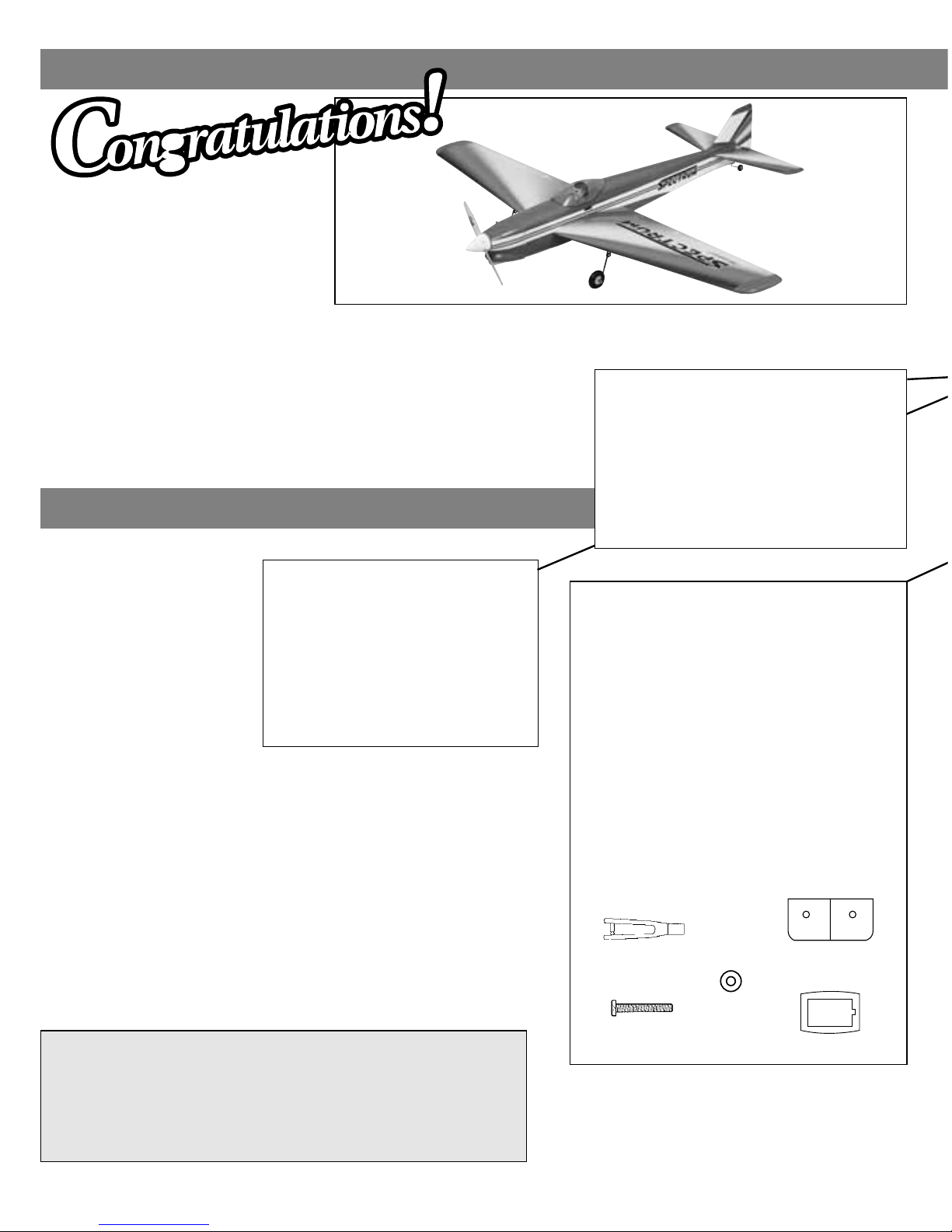
Take a moment now to
match the box contents
with the items listed
below. Following the
Spectrum assembly
instructions will be
quite
easy if you
identify and
organize the parts
before you begin.
Replacement Parts Available
HCAA3710...Wing Kit HCAA3714....Canopy
HCAA3711 ...Fuselage Kit HCAA3715....Landing Gear Set
HCAA3712...Fin Set HCAA3716....Spinner
HCAA3713...Cowl
Landing Gear
Part # Quantity
5 Landing Gear Blocks.................2
6 Landing Gear Struts (L&R) .......2
7 Wheels ......................................2
8 Tail Wheel..................................1
9 Landing Gear Cover Plates.......2
10 Plastic Gear Cover ....................2
Wing Assembly
Part # Quantity
11 Wing Joiner..............................................1
12 Right Wing Panel .....................................1
13 Left Wing Panel .......................................1
14 Wing Bolt Plate ........................................1
15 Aileron Servo Covers ...............................2
16 Retract Wheel Wells ................................2
17 Wing Mounting Plate................................1
18 Aileron Servo Tray ...................................2
19 Front Root Ribs........................................2
20 Rear Root Ribs ........................................2
* Clevises ...................................................2
* 4 x 35mm Bolt..........................................2
* 4mm Washer............................................2
18
14
Clevis
4mm
Washer
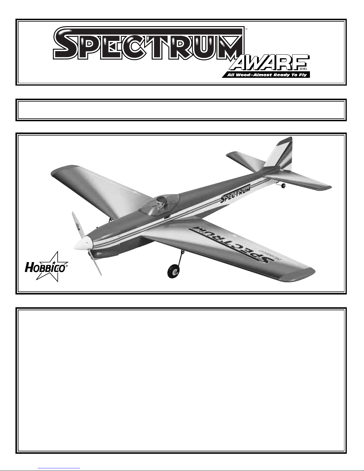
You’re about to build in just hours what took aviation
pioneers years—a powered machine that flies. Specially
created for you and other experienced radio control
modelers, Hobbico’s Spectrum offers nearly all the
excitement of piloting a real airplane...and develops skills
that will take you anywhere you want in your hobby.
*Parts marked with an asterisk are found on the plastic parts tree.
Know Your Model’s Parts
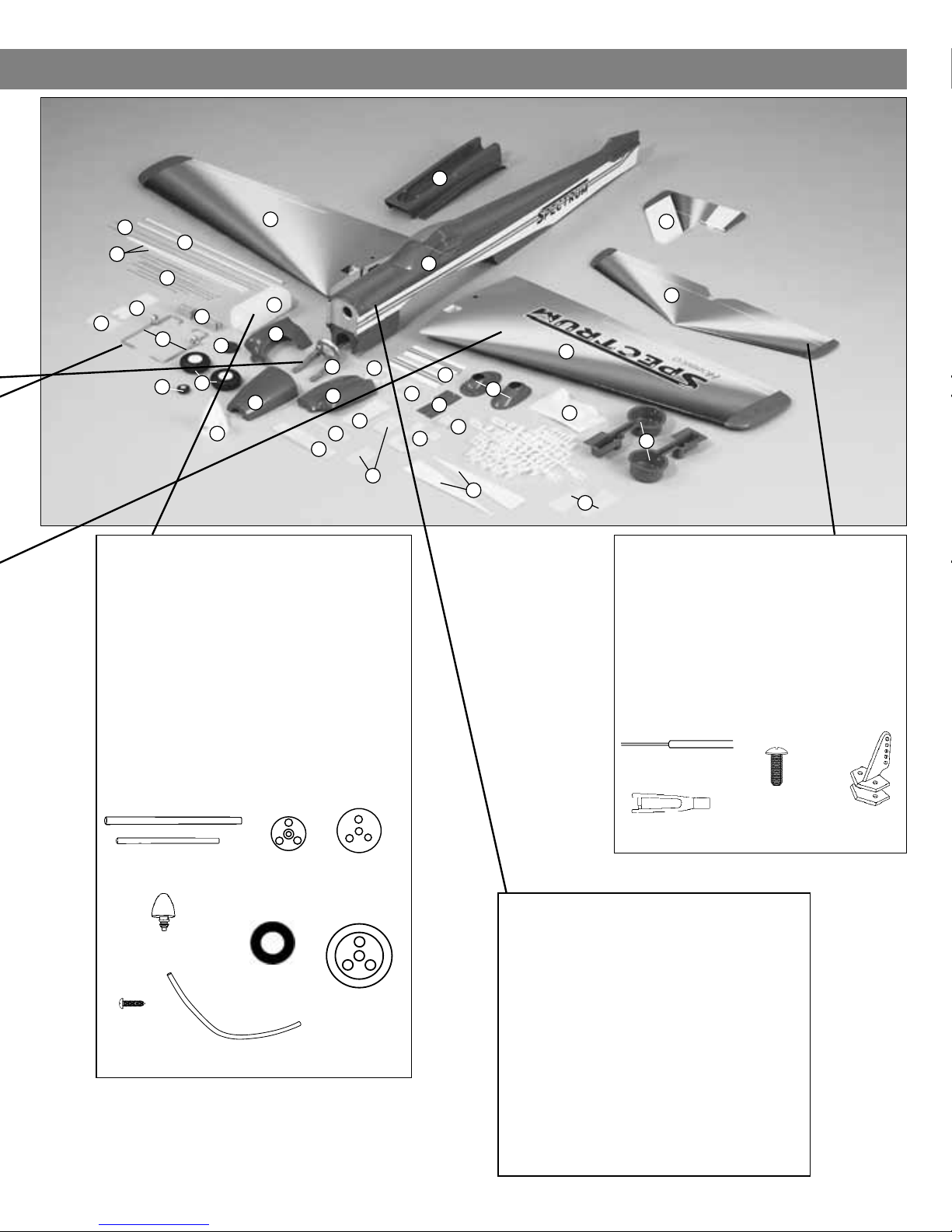
Engine Mounting Parts
Part # Quantity
1 Engine Mount ....................................1
2 Pushrod Tubes ..................................2
3 Pushrod Wire.....................................2
4 Pushrod Tubes ..................................2
4 x 35mm
Bolt
Page 3
3
Tail Assembly
Part # Quantity
23 Stabilizer and Elevator ..................1
24 Rudder and Fin .............................1
* Control Horns .................................2
* 2mm x 18mm Machine Screws ......4
* Clevises.........................................3
* Pushrod.........................................2
Clevis
2 x 18mm
Machine Screw
Fuse Parts
Part # Quantity
25 Fuselage ............................................1
26 Stab Base ..........................................1
27 Lower Wing Fairing ...........................1
28 Spinner ..............................................1
29 Cowl Decal ........................................2
30 Engine Mount Spacers ......................2
31 Cowl Side (L) .....................................1
32 Cowl Side (R) ....................................1
33 Cowl Top............................................1
34 Pilot....................................................1
35 Tuned Pipe Mount .............................1
3
3
24
27
25
23
11
26
20
34
19
29
35
28
33
31
32
21
13
10
17
30
30
16
15
18
12
22
13
5
4
6
8
9
14
2
1
Parts shown smaller than actual size (out of proportion).
Fuel Tank & Parts
• Parts Shown Below
Part # Quantity
21 Fuel Tank ...........................................1
22 Foam Fuel Tank Collar.......................2
* 3 x 18mm Screw ................................1
* Silicone Fuel Line...............................1
* Plastic Stopper Compression Disks
(One Large and One Small)...............2
* Fuel Pick-up Weight (Clunk) ..............1
* Rubber Tank Stopper.........................1
* Aluminum Fuel Tubing
(One Short and One Long) ................2
7
Plastic
Parts Tree
Plastic Stopper
Compression
Disks
Pushrod
Rubber Tank
Stopper
Silicone Fuel Line
Aluminum
Fuel Tubing
Clunk
3 x18mm
Screw
Foam Tank
Collar
Control
Horns
Page 4
4
Getting Ready for Flight
1. While building your Spectrum, make sure to follow the instructions. Do not alter or modify the model, as doing so may result in an unsafe or
unflyable model. In a few cases the instructions differ slightly from the photos. In those instances the instructions are correct.
2. You must install all components so the model operates on the ground as well as in the air.
3. You must check the operation of the model before EVERY flight to ensure all equipment is operating, and the model has remained structurally
sound. Be sure to check the clevises and other connectors often and replace them if they show signs of wear or fatigue
4. When you are preparing to go and fly your model, make sure to fully charge the radio system the night before, according to the manufacturer’s
instructions. Fully prepare your field box, making sure you have the necessary items for starting your engine. Remember to take along spare
propellers and glow plugs, as well as some epoxy and CA glue, just in case. Being prepared at the field will make your flying experience much
more enjoyable.
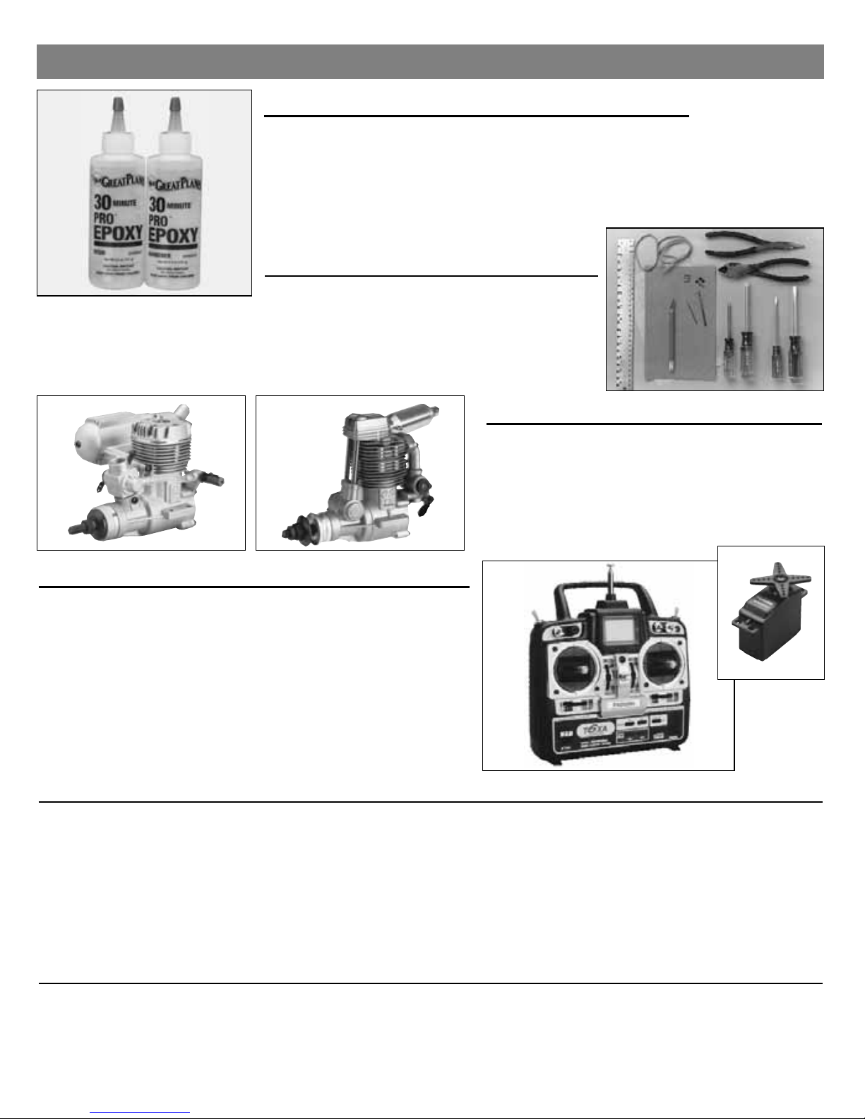
Other Items You’ll Need:
Glues
Choose 6-minute and 30-minute epoxy, such as Great Planes
®
Pro™Epoxy, which has been formulated especially for R/C model
building. Pro Epoxies offer a strong bond and a variety of curing
times suited for every step of assembly. You’ll also need a thin
instant-setting CA (cyanoacrylate), medium CA+, plus rubbing
alcohol for easy epoxy cleanup. Great Planes Pro Threadlocker is
also recommended to secure threaded fasteners.
Model Engine
Power your Spectrum with a hot 2-stroke such as an
O.S
®
. .46 FX, or SuperTigre®GS-45. If you prefer a
4-stroke, an O.S. FS-70 is an ideal choice. Your choice
of 2-stroke or 4-stroke will determine the location of the
throttle servo and throttle pushrod exit on the firewall,
so plan ahead.
Radio Equipment
In selecting a radio system for your Spectrum, you’ll need at least a
6-channel radio system with five standard servos. Many of the
6-channel radios offered include only four servos, so it may be
necessary to purchase an extra servo along with your radio system.
Unless you are planning to use a computer radio and mix the
throttle servos, you will also need a “Y” harness for your Spectrum.
The servos and receiver will be mounted on-board your model and
need to be cushioned from shock and vibration. One-half inch thick
foam rubber sheets (HCAQ1050) are available from your hobby
dealer for this purpose
.
Hardware
Tools and accessories required for assembly include
a hobby knife; small and large Phillips screwdrivers;
needle nose pliers; drill with 1/16", 5/64", 3/32", 1/8",
11/64", and 7/32" bits; ruler; 2 feet of medium (3/32")
fuel tubing; and 150 to 200-grit sandpaper.
Other General Items Required
Epoxy Brushes (GPMR8062) Mixing Sticks (GPMR8055) Clothespins 1/4" Foam Rubber (HCAQ1050)
T-Pins (HCAR5150) Masking Tape String Felt-Tip Pen
Sanding Block Adjustable Wrench Paper Towels Builders Triangle Set (HCAR0480)
Plastic Wrap or Wax Paper Round Toothpicks Wire Cutter Thread Locking Compound
70% Isopropyl Alcohol Small Hobby Clamps Razor Saw
Page 5
5
Your Hobbico Spectrum is not a toy, but rather
a sophisticated, working model that
functions
very much like an actual airplane. Because of its
realistic performance, the
Spectrum, if not
assembled and operated correctly, could
possibly cause injury to yourself or spectators
and damage property.
If this is your first low wing sport model, or
if you are uncomfortable in making the
initial flight of your Spectrum, it is
recommended that you get help from an
experienced, knowledgeable modeler with
your initial flights.
You may also want to contact the Academy of
Model Aeronautics (AMA), which has more
than 2,500 chartered clubs across the country.
Through the AMA, you should either be able to
locate a modeler nearby that can help, or at
least be able to phone one that can verbally
instruct you for any potential problems that
could occur. Contact the AMA at
the address or
phone number
below:
Academy of Model Aeronautics
5151 East Memorial Drive
Muncie, IN 47302
Office: (765) 287-1256
Toll Free: (800) 435-9262
Fax: (765) 741-0057
Internet:http://www.modelaircraft.org
Protect Your Model, Yourself & Others...
Follow This Important Safety Precaution
WARNING! This is not a Toy! Please follow these safety precautions:
Before you fly:
1. Make sure that no other fliers are using your radio
frequency.
2. Your radio transmitter must be the FIRST thing you
turn ON, and the LAST thing you turn OFF.
3. Double check all control surfaces.
4. Make sure that the transmitter & receiver batteries are
fully charged.
Fuel storage and care:
1. Do not smoke near your engine or fuel.
2. Store all engine fuel in a safe, cool, dry place, away
from children and pets. Model fuel will evaporate, so
make sure that you always store it with the
cap secure.
When starting and running your engine:
1. Always wear safety glasses.
2. Make certain that your glow plug clip is securely
attached to the glow plug and cannot pop off, possibly
falling into the spinning propeller.
3. Use a “chicken stick” or electric starter to start the
engine – NOT your fingers.
4. Make sure that the wires from your starter and glow
plug clip cannot become tangled with the spinning
propeller.
5. Do not stand at the side of the propeller when you
start or run the engine. Even at idle speed, the
spinning propeller will be nearly invisible.
6. If any engine adjustments are necessary, approach the
engine only from behind the spinning propeller.
JOIN THE AMA
0" 1" 2" 3" 4" 5"
0 10 20 30 40 50 60 70 80 90 100 110 120 130 140
Inch Scale
Metric Scale
Page 6
❏ 1. If you are planning to install retracts, remove
the wood from both wing panels for the retract
servo location. The wood has been partially precut
for exact location.
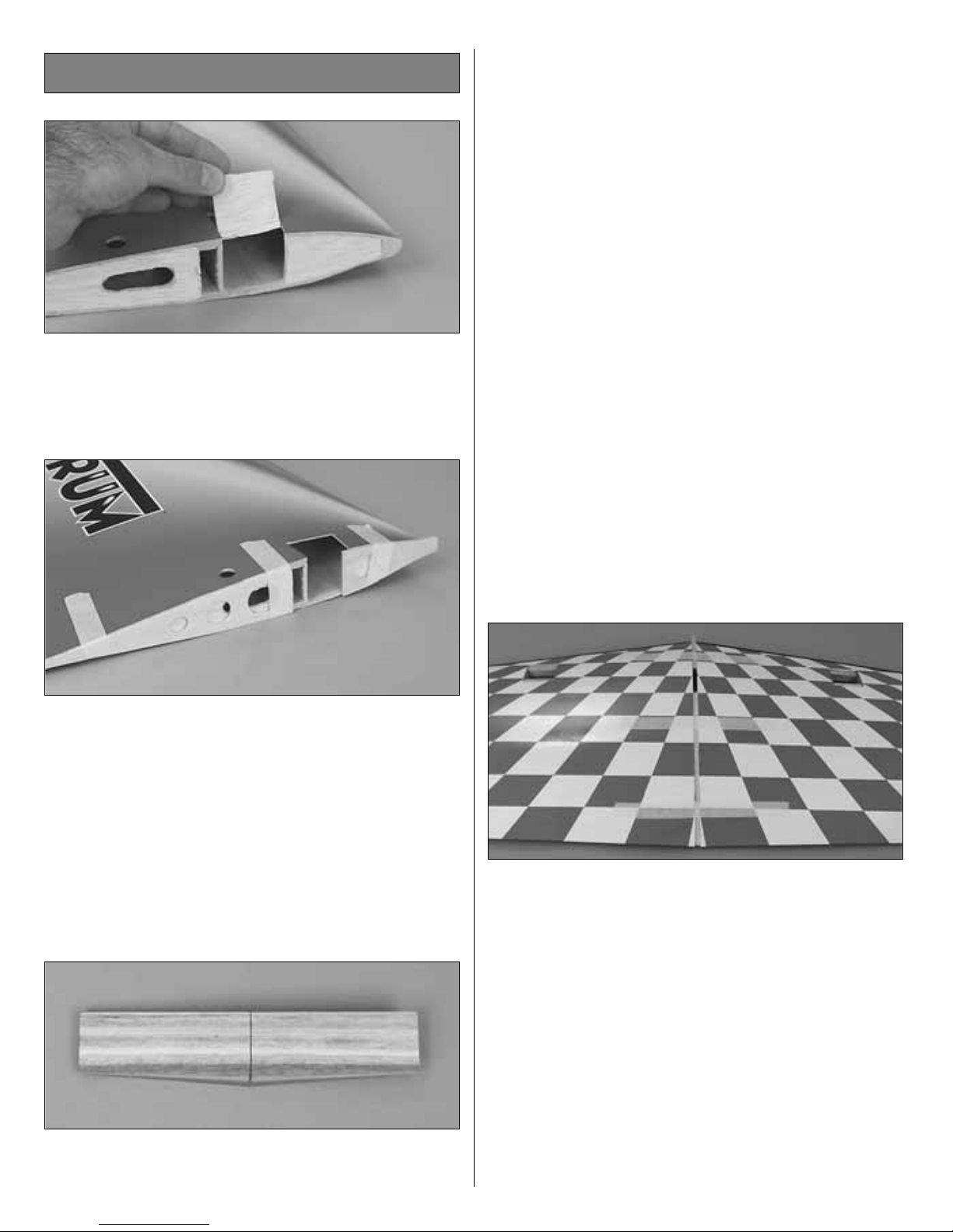
❏2. Test fit the plywood forward center rib and the
balsa aft center rib on the left wing panel. The ribs
should not protrude beyond the top and bottom of
the wing. The forward plywood rib will extend
beyond the leading edge of the wing. This
extension will lock the front of the wing into the
fuselage. Do not cut off the extension on the
plywood forward center rib. Use 30-minute
epoxy to glue the center ribs to the left wing panel.
Repeat this step for the right wing panel.
❏ 3. Draw a centerline on both sides of the wing
joiner. Test fit the wing joiner into both wing panels.
A snug fit is desirable. If the joiner does not fit
properly, lightly sand any uneven surfaces from the
joiner edges and sides. Note: The wing joiner has
a slight dihedral angle on one edge. This angle will
be on the bottom of the wing.
❏4. Test fit the wing halves with the wing joiner. If
necessary, sand any high spots on the root end of
the wing panels so there is no gap when you join
them. The top of the wing is flat, with the taper on
the bottom of the wing acting as dihedral. Because
of this, the wing can be joined with the top of the
wing laying flat on your work surface.
Note: The dihedral angle is established by the
angle of the root ribs and the dihedral brace. As
long as the wing halves fit together tightly, you will
have set the correct amount of dihedral.
Make a dry run of the following step without using
any glue so you will know how to clamp your wing
together.
❏ 5. Tape a piece of wax paper or plan protector
over your work surface. Thoroughly coat the joiner
pockets and the mating ends of both wing halves
with 30-minute epoxy. Set the wing halves aside
and proceed quickly. Coat all surfaces of one half
of the wing joiner with 30-minute epoxy and place
it in one of the wing halves. Coat the other half of
the joiner with 30-minute epoxy and join the other
wing. Use a piece of balsa or cardboard to wipe
away excess epoxy. Use masking tape to tightly
tape the wing together. Use a tissue dampened
with alcohol to wipe away any more epoxy that
oozes out of the wing, then set the wing aside. Do
not disturb the wing until the epoxy has fully cured.
Wing Assembly
6
Page 7
❏1. Remove the upper fuselage and lower
fuselage
pieces from the main fuselage. Set these aside in
a safe location for use later in the assembly of
your model.
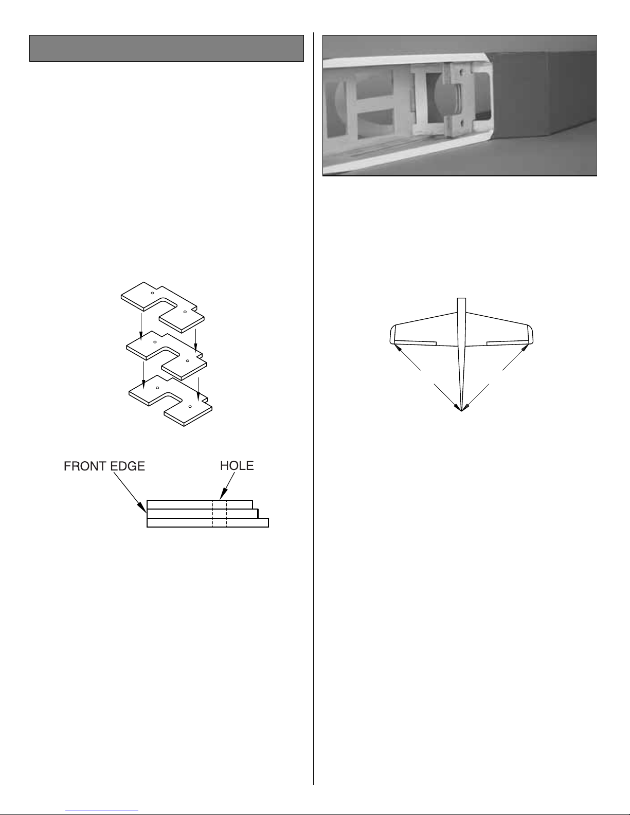
❏2. Locate the three plywood wing mounting plates.
Separate them and sand off any rough edges. Drill
a
7/32" [5.5mm] hole at the punch marks on the
plates.
❏3. Glue the three plates together in a stack with
the shortest on the top. Make sure the holes and
front edges are lined up with each other and wipe
off any excess epoxy using a paper towel and
rubbing alcohol. Use clothes pins to clamp the
plates together while the epoxy cures.
❏ 4. Install the blind nuts into the holes from the
bottom side of the mounting plate. (The short plate
is on the top.) Gently press the blind nuts into
position with a pliers or vise. Secure the blind nuts
into position with a drop of CA on the flange and
prongs of the nuts. Care must be taken not to get
CA into the threads of the blind nuts.
❏5. Test fit the wing mounting plate into position. Once
satisfied with the fit, secure it using 6-minute
epoxy.
❏ 6. Place the wing on the fuselage. Measure
from the aft center of the fuselage to one wing tip
and record the distance. Measure from the same
point to the opposite wing tip, and compare it to the
first measurement. If the measurements are not
the same, adjust the wing and re-measure until
they are equal. Place a mark on the wing so it can
be repositioned for the following step.
❏ 7. Insert the 4mm x 25mm wing bolts from the
under side of the wing mounting plate. The bolts
should slightly extend above the wing saddle so
they can lightly touch the wing when it is placed in
position. Paint the tips of the bolts with a slow
drying paint. Before the paint dries, place the wing
into the saddle, making sure it is in alignment.
Press the wing against the bolts so the paint
transfers
onto the wing, marking the location of the bolts.
A=A
A
A
Wing Installation
7
Page 8
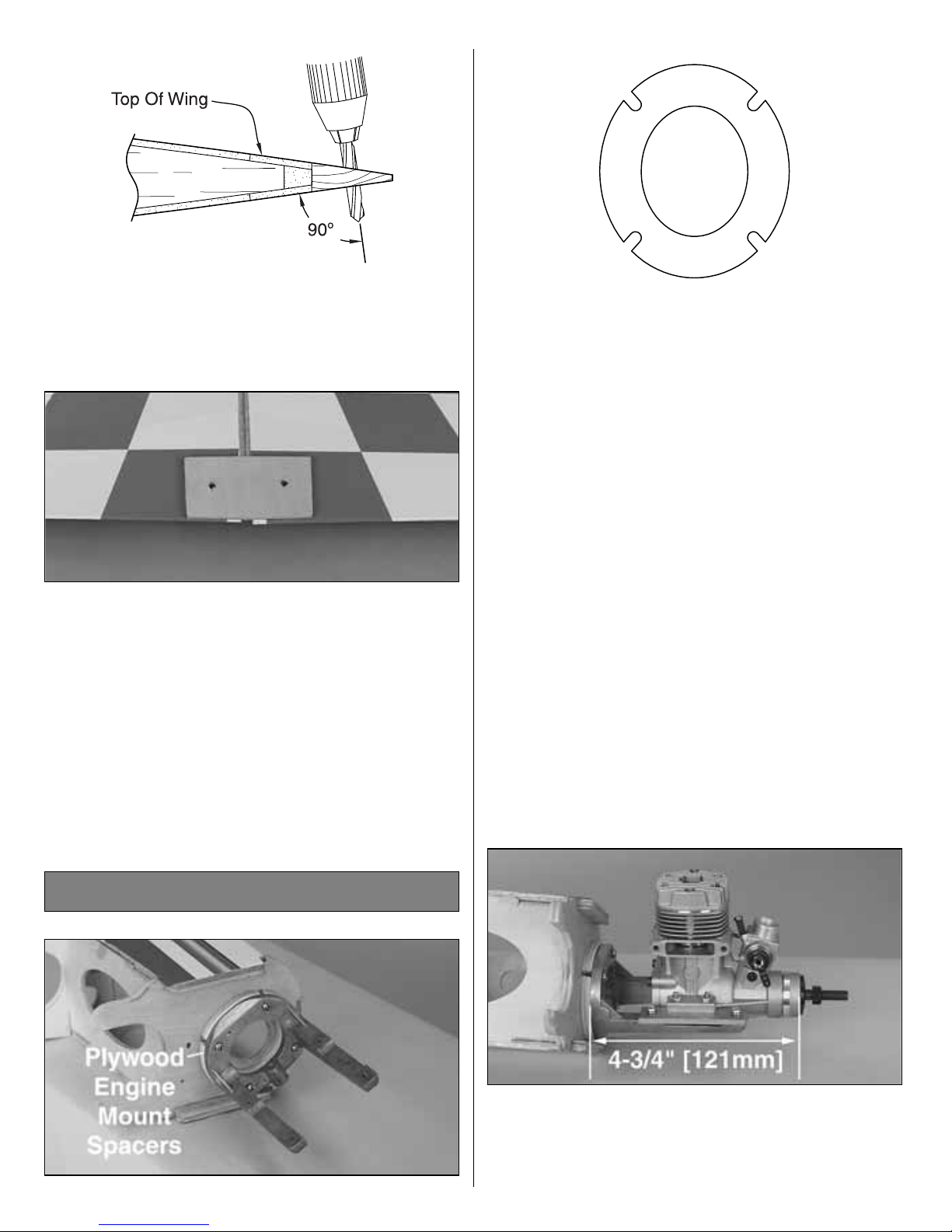
❏ 8. Drill a 11/64" [4.5mm] hole at each paint
mark. The drill should be perpendicular to the
bottom surface of the wing while drilling. The bolts
must thread into the blind nuts squarely.
❏ 9. Position the wing bolt plate onto the bottom
of the wing. The plate should be positioned to
equally cover both holes. Trace around the outside
of the plate using a felt-tip marker. Carefully
remove the covering from the wing where the plate
will be installed, making sure not to cut into the
underlying wood. Secure the wing bolt plate using
medium CA. Once the CA has cured, drill the plate
using a 11/64" [4.5mm] drill bit using the holes
drilled in the wing as a guide.
❏1. Place the two plywood engine mount spacers
behind the engine mount if you are using a
2-stroke engine. Use four 3mm x 20mm machine
screws to secure the engine mount to the firewall.
Blind nuts have already been installed in the
firewall for this purpose. (If you are using a 4-
stroke
engine, the spacers are not required.) Coat the
firewall, engine mount spacer and all other bare
wood around the firewall with fuelproof paint or
30-minute epoxy thinned with alcohol. Fuelproof
other areas of bare wood in the fuselage that may
be exposed to fuel or engine exhaust such as the
fuel tank area and the front and back of the wing
saddle. Avoid getting epoxy in the threads of the
blind nuts in the back of the firewall.
❏ 2. Temporarily attach the engine mount plates
to the engine mount using four 3mm x 12mm
machine screws. Adjust the width of the plates to
fit the engine, leaving a 1/16" [1.5mm] gap
between the engine and plates. Tighten the screws
so you can mark the engine mounting holes
without moving the plates.
❏ 3. Position the engine on the engine mount
plates so the propeller thrust washer (or spinner
backplate) is 4-3/4" [121mm] ahead of the firewall.
Use a sharpened piece of wire to scribe the four
Engine Installation
8
Page 9
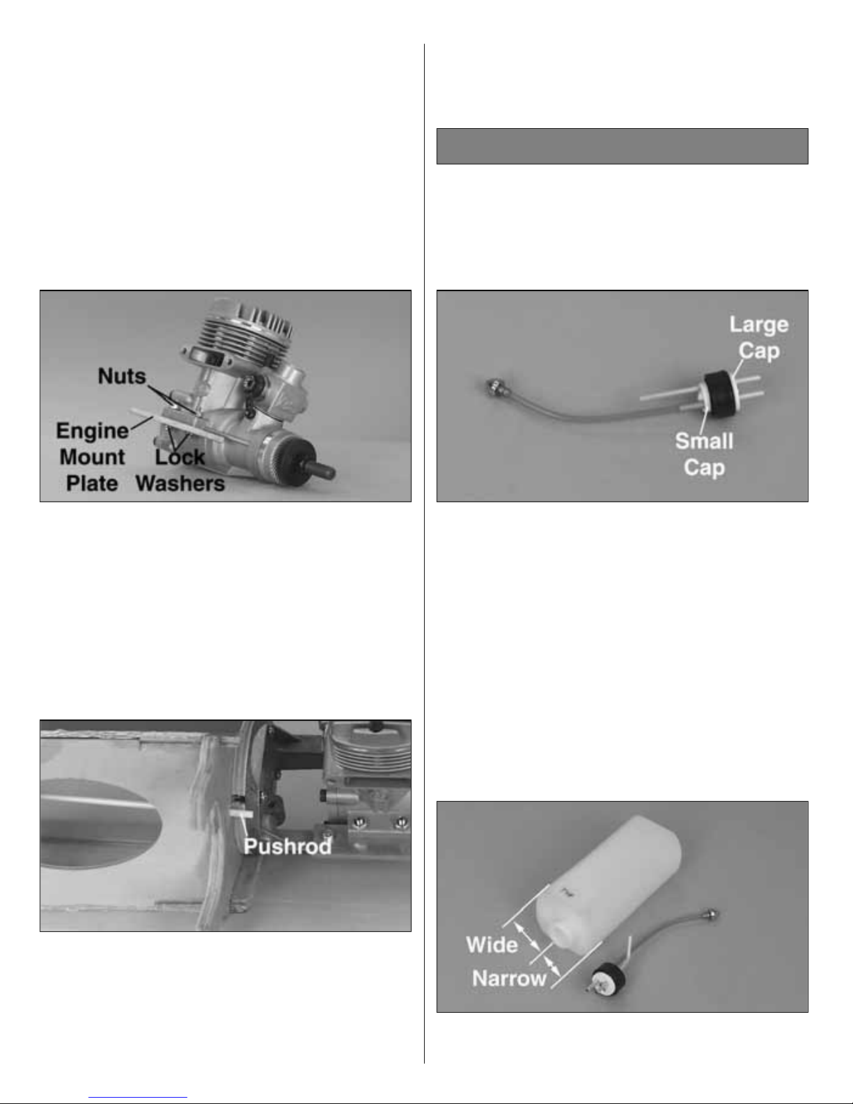
engine mount holes onto the rails. Use a center
punch at the marks to prevent the drill bit from
wandering, then drill 1/8" [3.1mm] holes through
the plates. Be sure to hold the drill perpendicular to
the rails. If you have access to a drill press, this is
a good tool for this purpose. Use four 3mm x
14mm machine screws, four 3mm nuts and four
3mm lock washers to secure the engine to the
mount. Use threadlock on the nuts to prevent
loosening.
❏ 4. Use the four 3mm x 12mm machine screws
and four 3mm lock washers to secure the engine
mount plates to the engine mount. Use threadlock
on the nuts to prevent loosening.
❏ 5. There is a 9/64" [3.6mm] hole in the firewall
for the throttle pushrod. Depending on your engine
selection, you may drill a new 9/64" [3.6mm] hole
for better pushrod placement.
❏ 6. Roughen the outside surface of the 13-3/4"
[350mm] throttle pushrod tube with coarse grit
sandpaper. Insert the pushrod tube through the
hole in the firewall which is in line with the throttle
arm on your engine. Push it in until about 1/4"
[6mm] of the tube is left exposed forward on the
firewall. Use medium CA to glue the tube to the
firewall, but leave it free inside the fuselage until
the servos are installed.
Note: There are three holes in the fuel tank
stopper but not all of the holes go all the way
through and only two are used for this model. Do
not puncture the third hole in the stopper.
❏ 1. Push the two aluminum tubes through the
rubber stopper until 1/2" [13mm] protrudes from
the front of the stopper. You will need to puncture
the rubber stopper on the back to push the tubes
through. Slide the large cap onto the front of the
stopper, and the small cap onto the back. Push
one end of the silicone pickup tube all the way onto
the clunk, and the other end all the way onto the
short aluminum tube. Insert the stopper screw into
the center hole in the front cap, then screw it
through the stopper into the aft stopper cap. Just
start the threads in the aft cap or you won’t be able
to insert the stopper into the tank.
❏ 2. Bend the long aluminum (vent) tube upward
at about a 45-degree angle, being careful not to
Fuel Tank Installation
9
Page 10

kink the tube. Test fit the stopper into the fuel tank.
The seam around the tank should be horizontal
and the stopper hole on the left as you look at the
front of the tank. By holding the tank up to the light
you will be able to see where the vent tube is, in
relation to the top of the tank. If necessary, bend
the vent tube to position it about 1/8" below the top
of the tank. When satisfied with the fit, make sure
the stopper is fully seated in the fuel tank. Tighten
the stopper screw until the plastic cap is indented
about 1/16". Doing so will lock the stopper into
position. Check the clunk and pickup tube to make
sure they move freely in the tank without binding or
stopping.
❏ 3. Locate the foam fuel tank collar and remove
the center portion. Install the collar to the front of
the fuel tank.
❏4. Before installing the tank, make sure the bent
vent tube points toward the top of the fuselage.
Apply a bead of 100% silicone sealer around the
sides of the rubber stopper and the front edge of
the fuel tank. Insert the tank fully into the tank
compartment while working the stopper into the
hole in the firewall. The silicone will seal the
opening and help hold the tank in position after it
has cured.
❏ 1. Locate the 1/8" [3mm] plywood stabilizer
mounting base and test fit to the fuselage. Lightly
sand the base if necessary to obtain a good fit.
Remove the base from the fuselage. Reinstall the
base using a generous amount of 30-minute
epoxy. Be sure there is enough epoxy to properly
secure the base to the fuselage. Remove any
excess epoxy from the outside of the fuselage with
a paper towel and rubbing alcohol.
❏2. Draw a centerline on the top of the horizontal
stabilizer (stab) from the aft edge to the leading
edge. Center the stab on the stab saddle using the
centerline, and slide it forward until the leading
Install the Tail Components
10
Page 11

edge contacts the fuselage. Perform the same
technique for aligning the stab as was used for
aligning the wing. This time, the center on the
fuselage is at the front, rather than the rear. Mark
the stab so it can be returned to its aligned
location.
❏ 3. Mount the wing to the fuselage using the
nylon bolts. Stand back 8 to 10 feet and view the
model from the front and rear. The stab tips should
be equally spaced above the level of the wing. If
not, lightly sand the high side of the stab saddle to
correct the problem. Work slowly and check the
alignment often.
❏ 4. Use a felt-tip pen to mark the sides of the
fuselage on the bottom of the stab. Remove the
stab from the fuselage.
❏5. Use a fresh #11 blade to carefully cut
through
the covering 1/16" [1.6mm] inside the lines you
marked on the bottom of the stab that indicate the
fuse sides. Do not cut the wood under the
covering! This will weaken the structure and
may cause the stab to fail in flight. Remove the
covering from the center of the stab within the lines
you cut. Remove a 1/4" [6mm] wide strip of
covering from the top of the stabilizer along the
centerline.
❏ 6. Use a liberal coating of 30-minute epoxy to
glue the stab in position. Hold the stab in position
with weights and clamps while the epoxy cures.
Double check alignment with the wing and fuse
while the epoxy cures. Important: Form a thin
epoxy fillet along the fuse sides where the epoxy
squeezes out to create a fuel proof seal between
the stab and fuselage.
11
Page 12

❏ 7. Drill a 3/32" [2.4mm] hole, 5/8" [16mm] up
from the bottom of the rudder. Cut a groove in the
LE of the rudder down to the bottom to
accommodate the tail gear wire. Hint: Use a 3/32"
[2.4mm] brass tube sharpened at the end to cut the
groove. (The Groove Tube™Grooving Tool
(GPMR8140) works great for this task.) Use 6minute epoxy to glue the tail gear wire to the
rudder.
❏ 8. Slide the Tail Gear Wire Brace onto the tail
gear wire. Use 30-minute epoxy to glue the fin in
position. Check the alignment of the fin to the stab
with a triangle, then secure it in position with
masking tape until the epoxy has cured. Double
check the alignment of the fin with the stab while
the epoxy cures.
❏9. Attach the tail gear wire brace to the fuselage
using two 3mm x 10mm sheet metal screws.
❏1. Mount the rudder, elevator and throttle servos
in the fuselage. Use the following sequence for
mounting the servos into the servo tray:
A. Install rubber grommets and brass eyelets in the
servos using the provided sketch.
B. Test fit the servos in the tray. Enlarge the
openings if needed to create a 1/32" gap around
the servo.
C. Mark servo mounting hole locations on the tray,
then drill 1/16" pilot holes through each mark.
D. Mount the servos with the screws provided with
your radio system.
❏2. Install and hook up - following the
manufacturer’s
recommendations - three servos, the receiver,
switch and battery as shown in the photo. We
added a Great Planes Switch Mount & Charge
Jack (GPMM1000, not included) for convenience
and ease of use at the field, installed on the side of
the fuselage. Center the elevator, rudder and
throttle trims on the transmitter.
Radio Installation
12
Page 13

❏ 3. Locate the two pre-bent, non-threaded
pushrod wires and the three threaded, pre-bent
pushrod wires. The
rudder pushrod will use one
threaded, and one non-
threaded wire. The elevator
pushrod will use one non-threaded and two
threaded wires.
❏ 4. Drill a 5/64" [2mm] hole 1" [25mm] in from
both ends of each pushrod. Cut a groove in the
dowel from the hole to the end of the dowel. For
the elevator, one end will be grooved on either side
to accept two pushrod wires.
❏ 5. Insert the bent end of one threaded piece of
wire into one end of each pushrod. (Two for the
elevator
pushrod.) Insert the bent end of the non-threaded
wires into the other end of each pushrod. CA the
wires in place.
❏ 6. Cut the heat shrink tubing into 1-1/2" [38mm]
lengths. Use the heat shrink tubing at each end of
the pushrod to hold everything in place as shown
in the photo. Apply a few drops of thin CA to each
end of the heat shrink tubing to secure it.
❏7. Use a sharp hobby knife to remove the
covering
from the pushrod exits. The photo shows both the
rudder and elevator exits cut out on the right side
of the fuselage. Remove only the covering from the
elevator exit on the left side.
❏ 8. Install the rudder nylon control horn in line
with the pushrod exit. Hold the horn in position and
INCORRECTCORRECT
HINGE LINE
13
Page 14

mark the location of the mounting holes. Drill 3/32"
[2.4mm] mounting holes through the marks. Wick
two to three drops of thin CA into the holes to
harden the underlying balsa,
then re-drill the holes.
Attach the horn using two 2mm x
15mm
machine
screws and a nylon nut plate. Do not over-
tighten
the screws, crushing the underlying balsa.
❏ 9. Install the rudder pushrod. Cut the 1-3/4"
[44mm] tubing into 1/4" [6mm] pieces to be used
as clevis retainers. Place a clevis retainer onto a
clevis. Thread the clevis 14 turns onto the pushrod.
Attach the clevis to the outside hole on the control
horn. Slightly bend the pushrod as necessary to
allow for free movement.
❏ 10. Center the rudder and rudder servo and
mark the pushrod where it crosses the servo arm.
Enlarge the servo horn hole with a 5/64" [2mm] drill
bit. (The Hobbico Quick Drill set (HCAR0699)
works
well for this purpose.)
❏ 11. Make a 90-degree bend in the pushrod on
your mark, then insert it through the enlarged hole
in the servo arm. Secure the wire in place with a
nylon pushrod keeper. Trim the excess wire 1/16"
[1.6mm] above the pushrod keeper.
❏ 12. Install the elevator control horns by
positioning the horns as close to the inboard edge
of the elevators as possible and mark the location
of the mounting holes. Drill 3/32" [2.4mm]
mounting
holes through the marks. Wick two to three drops
of thin CA into the holes to harden the underlying
balsa, then re-drill the holes. Attach the horns
using four 2mm x 15mm machine screws and two
nylon nut plates. Do not over-tighten the screws,
crushing the underlying balsa.
❏ 13. Install the elevator pushrod. Place two
clevis retainers onto two clevises. Thread the
clevises 14 turns onto the pushrod. Attach the
clevises to the outer holes of the control horns.
14
Page 15

Slightly bend the pushrod wires as necessary to
allow for free movement.
❏14. Center the elevators and elevator servo and
mark the pushrod where it crosses the servo arm.
Enlarge the servo horn hole with a 5/64" [2mm]
drill bit.
❏ 15. Make a 90-degree bend in the pushrod on
your mark, then insert it through the enlarged hole
in the servo arm. Secure the wire in place with a
nylon pushrod keeper. Trim the excess wire 1/16"
[1.6mm] above the pushrod keeper. Use a
straightedge
to line up the elevators. Adjust the clevises if
necessary if the elevators are not aligned.
❏16. Attach the throttle pushrod connector to the
throttle servo arm. The 2mm washer and 2mm nut
are located on the bottom of the servo arm. Use
threadlock on the nut to prevent loosening.
❏ 17. Install the throttle pushrod into the pushrod
tube. Connect the pushrod to the throttle arm of the
engine using a “Z” bend. Bend the throttle pushrod
as necessary to reach the throttle arm without
binding. When satisfied with the fit, insert the
pushrod
through the pushrod connector on the servo.
❏18. With the radio on move the throttle trim and
control stick to the fully closed position, by pulling
them back (or downward) all the way. Manually
close the throttle on the carburetor completely.
Tighten the 3mm x 6mm screw on the pushrod
connector. Check throttle operation with the radio
and make adjustments to the linkages as
necessary for smooth operation. Use the
appropriate
holes in the servo and throttle arms to provide the
correct amount of throttle movement and to
prevent the servo from binding at its end points.
Cut a notch in the plywood former to support the
pushrod tube inside the fuselage as shown in the
photo. Use threadlock on the screw to prevent
loosening.
15
Page 16

❏19. Locate the two plywood aileron servo trays.
Position the aileron servo trays onto the bottom of
the wing, centering them over the holes in the wing
for the aileron servos. Trace around the outside of
the servo tray using a felt-tip marker. Remove the
covering from the wing where the tray will be
installed. Secure the aileron servo trays using
medium CA.
❏ 20. Tie one of the wheel collars onto a string.
While holding onto the end of the string, drop the
end with the wheel collar into the wing from the
servo opening. The wheel collar and string can
then be retrieved from the hole in the center of the
wing. Repeat the step for the other wing panel.
❏ 21. Install the rubber grommets and eyelets in
your aileron servos. Attach a servo extension to
the aileron servo. Use heat-shrink tubing or
electrical tape to secure the servo cord to the
extension so they don’t unplug in flight. Pull the
string part way out of one of the aileron servo
compartments in the wing. Remove the wheel
collar and tie the string to the servo cord on one of
the aileron servos. Gently pull the servo lead
through the wing panel. Repeat the step for the
other wing panel.
❏ 22. Fit one of the aileron servos in the wing.
Hold the servo in the wing so the sides don’t
contact the tray and drill 1/16" [1.6mm] holes for
the servo mounting screws. Mount the servo to the
wing with the screws included with your servos.
❏ 23. Mount your other aileron servo in the
opposite wing panel using the same procedures
16
Page 17

as above.
❏ 24. Install the aileron nylon control horns. The
control horns are positioned 1/2" [13mm] towards
the tip of the wing from the centerline of the servo.
Hold the horn in position and mark the location of
the mounting holes. Drill 3/32" [2.4mm] mounting
holes through the marks. Wick two to three drops
of thin CA into the holes to harden the underlying
balsa, then re-drill the holes. Attach the horns
using four 2mm x 15mm machine screws and two
nylon nut plates. Do not over-tighten the screws,
crushing the underlying balsa.
❏ 25. Connect the aileron servos to the receiver,
turn on the radio, then center the servo horn. The
servo horns should be facing opposite each other
as shown in the sketch if you are planning on using
a “Y” harness for the aileron servos or a computer
radio. Place a clevis retainer onto a clevis. Thread
the clevis 14 turns onto one of the 7-7/8" [200mm]
pushrods. Attach the clevis to the second hole
from the outside hole on the control horn.
❏ 26. Attach the clevises to the second hole from
the top of the control horns. Center the ailerons,
then mark the pushrods at the point where they
meet the holes on the servo arm. Make a 90degree bend in the wires at this mark. Cut off the
excess wire 3/8" [9.5mm] above the bend. Enlarge
the servo horn holes with a 5/64" [2mm] drill bit.
Insert the bent wire pushrods into the servo horn,
then secure them with nylon pushrod keepers.
❏1. Test fit the aileron servo covers. Carefully trim
any portion of the covers that interfer with the
operation of the aileron pushrods and servo horns.
Tape the covers into position. Wick thin CA
between the cover and wing to secure each of
Final Assembly
17
Page 18

them to the wing.
❏ 2. Use a sharp hobby knife, scissors or Lexan
®
shears to trim the upper fuselage at the rear for the
fin and stabilizer.
❏ 3. Test fit the upper fuselage to the stabilizer
and rudder, as well as the main fuselage. Trim as
necessary to prevent any binding of the control
surfaces. Remove the upper fuselage, and
roughen
the bottom 1/8" [3mm] of the inside edge. Glue the
upper fuselage to the main fuselage using 30-
minute
epoxy or R/C-56 glue. Use masking tape to hold it
in position until the glue has cured. Use a tissue
dampened with alcohol to wipe away any epoxy
that oozes out, then set the fuselage aside.
Note: The upper fuselage can also be glued using
thin CA. Tape the upper fuselage into position,
spacing the tape about 3" [75mm] apart. Place a
drop of thin CA between the pieces of tape to tack
the upper fuselage into position. Remove the tape,
and wick thin CA along the seam between the
upper fuselage and main fuselage. There is a
chance the CA may drip along the upper fuselage
and ruin the finish, so work slowly to obtain the
best finish.
❏ 4. Use the same gluing technique to glue the
lower fuselage to the main fuselage as shown.
The following steps cover fitting the cowl to an O.S.
engine using the stock muffler. This is the most
often used engine configuration as it allows for
adequate engine cooling and muffler installation.
❏ 5. Tape the upper, left and right cowl pieces
together to check the fit. Test fit the cowl to the
fuselage. Slowly trim the cowl to fit into position.
Once satisfied with the fit of the cowl onto the
fuselage, wick thin CA along the seams to glue the
cowl together. If the cowl is a tight fit, the seam at
the bottom can be left slightly apart, as this area
18
Page 19

will be removed for the muffler.
❏ 6. Slide the cowling into position. Temporarily
attach the propeller and spinner to the engine.
Position the cowling to have 1/8" [3mm] clearance
between the spinner backplate and the front of the
cowling. Drill 1/16" [1.6mm] pilot holes for the cowl
screws. Remove the cowling, and drill the locations
for the cowl mounting screws using a 1/8" [3mm]
drill bit. Wick thin CA into the holes on the fuselage
to harden the wood, which will prevent the screws
from stripping the underlying wood. Attach the
cowling to the fuselage using four 3mm x 10mm
sheet metal screws.
❏ 7. Attach the muffler to the engine. Carefully
trim the cowl, removing small amounts of material
as you progress to allow for a 1/4" [6mm]
clearance gap between the cowl and the muffler.
❏ 8. Apply the decals to the cowling, lining them
up with the trim scheme on the fuselage.
Note: Use scraps from the plastic sheets to make
reinforcements behind the holes of the cowling. It
is also suggested to apply a strip of fiberglass cloth
along the inside seam of the cowling for added
strength and durability.
❏ 9. Attach and install the fuel lines to the
carburetor and muffler as shown in the photo.
Attach the vent line to the muffler, and the fuel line
(with the clunk) to the carburetor (or needle valve
assembly).
Note: If your engine’s carburetor is inaccessible
with the cowl in position, now would be a good time
to add a Great Planes Fuel Filler Valve (not
included,
GPMQ4160) to the side of your aircraft. Instructions
for installation are included with the valve.
Use a sharp hobby knife, scissors or Lexan
®
shears to trim the pilot figure. Lightly sand the
mating surfaces. Hold the two parts of the pilot
Finishing the Cockpit
19
Page 20

together, then wick thin CA into the joint.
Paint the pilot and cockpit to your liking with
enamel model paint, then glue it into the cockpit
using medium CA or 6-minute epoxy.
Roughen the bottom 1/8" [3mm] of the inside
canopy edge, being careful not to scratch any
exposed areas. Glue the canopy into position with
6-minute epoxy or R/C-56 glue. Apply a piece of
trim tape to the outside of the canopy to add detail
and hide the glue joint.
❏ 1. Place the landing gear mounting blocks in
between the U-bend on the top portion of the main
landing gear struts.
❏ 2. Using a pen, place marks on the mounting
blocks using the flat metal straps as templates.
Pre-drill the screw holes using a 1/16" [1.6mm] drill
bit and secure the strut with four metal straps and
eight 3mm x 10mm sheet metal screws.
❏3. Locate the plywood landing gear cover
plates.
Drill four holes in each plate at the punch marks
using a 1/8" [3mm] drill bit.
❏ 4. Use 6-minute epoxy to glue the plywood
Fixed Gear Installation
Wheel Installation
20
Page 21

landing gear cover plates to the mounting blocks.
❏5. Position the landing gear assemblies into the
wing. The struts will be placed towards the tip of
the wing. Drill 1/16" [1.6mm] pilot holes into the
landing gear rails using the holes in the landing
gear cover plate as a template. Secure the landing
gear into position using eight 3mm x 10mm sheet
metal screws.
❏6. Install the main wheels using four 4mm wheel
collars and four 3mm x 6mm machine screws.
Grind or file a flat spot at the point of set screw
contact. This provides a better area for the screw
to bite and helps keep the wheel in place. Trim off
any excess axle wire after installing the outer
wheel collars. Use threadlock on the screws to
prevent loosening.
Note: None of the hardware used in the retract
installation is included in the kit. All hardware must
be purchased separately.
❏1. Locate the plywood retract servo tray.
Separate
the supports from the main tray and sand off any
rough edges. Use medium CA to glue the supports
to the tray at 90-degree angles to the tray.
❏ 2. Glue the retract servo tray assembly into the
wing as shown using 6-minute epoxy. Test fit the
retract servo in the servo tray after the epoxy has
cured. Enlarge the opening in the tray if necessary
to provide a 1/32" [1mm] gap around the servo
when installed. Mount the servo into place using
the hardware supplied with the servo.
❏ 3. Using a sharp hobby knife, remove the
material from the bottom of the wing for the wheel
wells and retract struts. The outline for the wells
Retract Installation
21
Page 22

are embossed into the wing sheeting, and can be
seen easier if the covering is pressed down
against the sheeting in the area of the wheel well
using your index finger. (Be careful not to
accidentally break the sheeting.)
❏ 4. Place a clevis retainer onto a clevis. Thread
the clevis 14 turns onto a 12" [300mm] pushrod.
Attach the clevis to the actuating arm on the retract.
Test fit the retract into the wing. Trim the wing
sheeting as necessary to allow the retract to seat
fully onto the retract rails. Drill 1/16" [1.6mm] pilot
holes into the landing gear rails using the holes in
the retract as a template. Secure the retract into
position using four 3mm x 10mm sheet metal
screws. Repeat the step for the opposite side.
❏ 5. Use Quick Connectors on the servo arm to
connect the retract pushrods. Using the radio,
cycle the retracts to make sure they will lock in
both the up and down positions. Adjust the
positions of the quick connectors on the servo arm
if necessary to allow the retracts to lock in both the
up and down positions.
❏ 6. Once you have adjusted the linkages, test fit
the retract wheel wells into position. Use medium
CA to glue the wells to the wing.
❏7. Install the landing gear struts into the retracts.
Using a pen, mark the strut 1/4" [6mm] past the
center of the wheel well when the retracts are
folded into the wing. Cut the landing gear struts off
at the mark and file the edges of the wire to remove
the rough edges.
❏8. Use an adjustable axle to mount the wheel to
the landing gear strut. Place the axle onto the strut,
and secure its location using the set screw
provided with the axle. Install the main wheels
using eight 4mm wheel collars and eight 3mm x
22
Page 23

6mm machine screws. Grind or file a flat spot at
the point of set screw contact. This provides a
better area for the screw to bite and helps keep the
wheel in place. Trim off any excess axle wire after
installing the outer wheel collars. Cycle the retract
and adjust the position of the axle and wheel to
prevent any binding of the wheel in the well. Mark
the location at which the set screw in the axle
contacts the strut, and grind or file a flat spot at the
point of set screw contact. This provides a better
area for the screw to bite and prevents the axle
from rotating on the strut. Use threadlock on the
screws to prevent loosening.
❏ 1. Just so you don’t forget, the tail wheel must
be installed in order to taxi the aircraft. Slide the tail
wheel onto the tail gear, and use a 2mm wheel
collar and the 3mm set screw to keep the wheel
attached to the gear.
❏ 1. Prepare the lower wing fairing by drilling the
indentations at the rear of the fairing for the wing
bolts using a 1/4" [6mm] drill bit. Cut a notch in the
front of the fairing to allow for clearance of the
center ribs on the wing.
Note: If you plan on installing a tuned pipe, use 6minute epoxy to glue the hardwood mount to the
lower wing fairing.
❏ 2. Attach the wing using two 4mm bolts.
Position the lower wing fairing onto the bottom of
the wing, and align it with the fuselage. Use 30-
minute
epoxy or R/C-56 glue to attach the fairing to the
wing (but not the fuselage!)
Note 1: If you are installing a tuned pipe, remove a
section of the wing covering to glue the hardwood
mount to the wing sheeting. Use 6-minute epoxy to
glue the mount to the wing sheeting.
Note 2: If you are installing retracts, the lower wing
fairing
must be trimmed as shown in the photo to
allow for
clearance of the wheel wells.
❏ 1. Hook up
the receiver, switch and battery,
(following the manufacturer’s
recommendations),
Battery & Receiver InstallationLower Fairing Installation
Tail Wheel Installation
23
Page 24

as shown in the photo. We added a Great Planes
Switch Mount & Charge Jack (GPMM1000, not
included) for convenience and ease of use at the
field, installed on the side of the fuselage. At this
time, it is suggested to allow the receiver and
battery the option of being moved until after the
aircraft has been balanced. Once balanced, the
receiver and battery should be secured into the
aircraft to prevent them from moving during flight.
❏ 2. Route the antenna to the tail of the model.
You may use your preferred method or the method
we use in the Great Planes model shop. Drill a
15/64" hole through the fuse side in the proximity
of the receiver. Cut a 1/2" long piece of fuel tubing
and install it in the hole. Install a strain relief (as
shown in the sketch), then route the antenna
through the fuel tubing to the bottom of the fuse at
the tail. Use a rubber band to attach the antenna to
a T-pin at the aft end of the
fuselage. Do not cut or
shorten the antenna wire. Leave
any excess to
hang free.
By moving the position of the clevis at the control
horn toward the outermost hole, you will decrease
the amount of throw of the control surface. Moving
it toward the control surface will increase the
amount of throw. If these adjustments don’t
accomplish the job, you may need to work with a
combination of adjustments by also repositioning
the pushrod at the servo end. Moving the pushrod
towards the center of the servo horn will decrease
the control surface throw - outward will increase it.
Note: Throws are measured at the widest part of
the elevators, rudder and ailerons. If your radio
does not have dual rates, set the control throws to
halfway between the specified high and low rates.
We recommend the following control surface
throws as a starting point:
One leading cause of crashes is flying an airplane
with its control throws set differently from those
recommended in
the instructions. The Great Planes
AccuThrow™(GPMR2405) lets you quickly and
easily measure actual throws first, so you can
make necessary corrections before you fly. Large,
no-slip rubber feet provide a firm grip on covered
surfaces without denting or marring the finish.
Spring tension holds AccuThrow’s plastic ruler
steady by each control surface. Curved to match
control motions, the ruler provides exact readings
High Rate Low Rate
Elevator 5/16" [8mm] Up 3/16" [5mm] Up
5/16" [8mm] Down 3/16" [5mm] Down
Rudder 1" [25mm] Right 5/8" [16mm] Right
1" [25mm] Left 5/8" [16mm] Left
Ailerons 3/8" [9.5mm] Up 1/4" [6.5mm] Up
3/8" [9.5mm] Down 1/4" [6.5mm] Down
Control Surface Throws
Control Throw Adjustment
24
Page 25

in both standard or metric measurements.
Make sure the control surfaces move in the proper
direction as illustrated in the following sketch:
Note: This section is VERY important and must
NOT be omitted! A model that is not properly
balanced will be unstable and possibly unflyable.
❏ 1. The balance point (C.G.) is located 5-1/4"
[132mm] back from the leading edge of the wing.
Balance your Spectrum using a Great Planes C.G.
Machine™Airplane Balancer (GPMR2400) for the
most accurate results. This is the balance point at
which your model should balance for your first
flights. After initial trim flights and when you
become more acquainted with your Spectrum, you
may wish to experiment by shifting the balance up
to 5/16" [8mm] forward or backward to change its
flying characteristics. Moving the balance forward
may improve the smoothness and stability, but the
model may then require more speed for takeoff
and may become more difficult to slow for landing.
Moving the balance aft makes the model more
agile with a lighter, snappier “feel” and often
improves knife-edge capabilities. In any case,
please start at the location we recommend. Do not
at any time balance your model outside the
recommended range.
❏ 2. With the wing attached to the fuselage, all
parts of the model installed (ready to fly), and an
empty fuel tank, block up the tail as necessary to
level the stab. Lift the model at the desired balance
point, and observe the tail of the aircraft. If the tail
drops, the model is “tail heavy” and you must add
weight* to the nose to balance the model. If the
nose drops, it is “nose heavy” and you must add
weight* to the tail to balance the model.
Note: Nose weight may be easily installed by
using
a “spinner weight.” Tail weight may be added by
using
Great Planes (GPMQ4485) “stick-on” lead
weights.
* If possible, first attempt to balance the model by
changing the position of the receiver battery. If you
are unable to obtain good balance by doing so,
then it will be necessary to add weight to the nose
or tail to achieve the proper balance point.
Remember to secure the receiver and battery after
your model has been balanced.
IMPORTANT: Do not confuse this procedure with
“checking the C.G.” or “balancing the airplane fore
and aft.”
Now that you have the basic airplane nearly
completed, this is a good time to balance the
airplane laterally (side-to-side). Here is how to do
it:
Balance Your Model Laterally
Balance Your Model
CARBURETOR WIDE OPEN
RUDDER MOVES RIGHT
LEFT AILERON MOVES DOWN
RIGHT AILERON MOVES UP
ELEVATOR MOVES UP
4-CHANNEL
TRANSMITTER
(STANDARD MODE 2)
4-CHANNEL RADIO SETUP
TRANSMITTER
4-CHANNEL
TRANSMITTER
4-CHANNEL
TRANSMITTER
4-CHANNEL
25
Page 26

❏ 1. Assemble the model in as in preparation for
flight. (No fuel is required for this procedure.)
❏ 2. With the wing level, lift the model by the
engine propeller shaft and the fin post (this may
require two people). Do this several times.
❏ 3. If one wing always drops when you lift the
model, it means that side is heavy. Balance the
airplane by adding weight to the opposite, lighter
wing tip.
Note: An airplane that has been laterally balanced
will track better in loops and other maneuvers.
At this time check all connections including servo
horn screws, clevises, servo cords and extensions.
Charge the Batteries
Follow the battery charging procedures in your
radio instruction manual. You should always
charge your transmitter and receiver batteries the
night before you go flying and at other times as
recommended by the radio manufacturer.
Balance the Propeller
Carefully balance your propellers before flying. An
unbalanced prop is the single most significant
cause of vibration. Not only may engine mounting
screws vibrate out, possibly with disastrous effect,
but vibration may also damage your radio receiver
and battery. Vibration may cause your fuel to foam,
which will, in turn, cause your engine to run lean
or quit.
We use a Top Flite Precision Magnetic Prop
Balancer™(TOPQ5700) in the workshop and keep
a Great Planes Fingertip Balancer (GPMQ5000) in
our flight box.
Find A Safe Place to Fly
Since you have chosen the Spectrum ARF, we
assume that you are an experienced modeler.
Therefore, you should already know about AMA
chartered flying fields and other safe places to fly.
If for some reason you are a relatively
inexperienced modeler and have not been
informed, we strongly suggest that the best place
to fly is an AMA chartered club field. Ask the AMA
or your local hobby shop dealer if there is a club in
your area and join. Club fields are set up for R/C
flying and that makes your outing safer and more
enjoyable. The AMA address and telephone
number are in the front of this manual. If a club and
flying site are not available, find a large, grassy
area at least 6 miles away from houses, buildings
and streets and any other R/C radio operation like
R/C boats and R/C cars. A schoolyard may look
inviting but is too close to people, power lines and
possible radio interference.
Ground Check the Model
Inspect your radio installation and confirm that all
the control surfaces respond correctly to the
transmitter inputs. The engine operation must also
be checked by confirming that the engine idles
reliably, transitions smoothly and rapidly to full
power and maintains full power, indefinitely. The
engine must be “broken-in” on the ground by
running
it for at least two tanks of fuel. Follow the
engine
manufacturer’s recommendations for
break-in.
Make sure that all screws remain tight, that the
hinges are secure and that the prop is on tight.
Range Check Your Radio
Whenever you go to the flying field, check the
operational range of the radio before the first flight
of the day. First, make sure no one else is on your
frequency (channel). With your transmitter on, you
should be able to walk at least 100 feet away from
the model and still have control. While you work
the controls, have a helper stand by your model
and tell you what the control surfaces are doing.
Repeat this test with the engine running at various
speeds with a helper holding the model. If the
control surfaces are not always responding
correctly, do not fly! Find and correct the problem
first. Look for loose servo connections or corrosion,
Preflight
26
Page 27

loose bolts that may cause vibration, a defective
on/off switch, low battery voltage or a defective
receiver battery, a damaged receiver antenna, or a
receiver crystal that may have been damaged from
a previous crash.
Engine Safety Precautions
Note: Failure to follow these safety precautions
may result in severe injury to yourself and others.
Keep all engine fuel in a safe place, away from
high heat, sparks or flames, as fuel is very
flammable. Do not smoke near the engine or fuel;
and remember that the engine exhaust gives off a
great deal of deadly carbon monoxide. Do not run
the engine in a closed room or garage.
Get help from an experienced pilot when learning
to operate engines.
Use safety glasses when starting or running
engines. Do not run the engine in an area of loose
gravel or sand; the propeller may throw such
material in your face or eyes.
Keep your face and body as well as all spectators
away from the plane of rotation of the propeller as
you start and run the engine.
Keep these items away from the prop: loose
clothing, shirt sleeves, ties, scarfs, long hair or
loose objects such as pencils or screwdrivers that
may fall out of shirt or jacket pockets into the prop.
Use a “chicken stick” or electric starter to start the
engine. Do not use your fingers to flip the propeller.
Make certain the glow plug clip or connector is
secure so that it will not pop off or otherwise get
into the running propeller.
Make all engine adjustments from behind the
rotating propeller.
The engine gets hot! Do not touch it during or right
after operation. Make sure fuel lines are in good
condition so fuel will not leak onto a hot engine,
causing a fire.
To stop a glow engine, cut off the fuel supply by
closing off the fuel line or following the engine
manufacturer’s recommendations. Do not use
hands, fingers or any other body part to try to stop
the engine. Do not throw anything into the
propeller of a running engine.
Read and abide by the following Academy of
Model Aeronautics Official Safety Code:
General
1. I will not fly my model aircraft in sanctioned
events, air shows, or model flying demonstrations
until it has been proven to be airworthy by having
been previously successfully flight tested.
2. I will not fly my model aircraft higher than
approximately 400 feet within 3 miles of an airport
without notifying the airport operator. I will give
right of way to and avoid flying in the proximity of
full-scale aircraft. Where necessary an observer
shall be used to supervise flying to avoid having
models fly in the proximity of full-scale aircraft.
3. Where established, I will abide by the safely
rules for the flying site I use and I will not willfully
and deliberately fly my models in a careless,
reckless and/or dangerous manner.
7. I will not fly my model unless it is identified with
my name and address or AMA number, on or in
the model.
9. I will not operate models with pyrotechnics (any
device that explodes, burns, or propels a projectile
or any kind).
Radio Control
1. I will have completed a successful radio
equipment ground check before the first flight of a
new or repaired model airplane.
2. I will not fly my model aircraft in the presence of
spectators until I become a qualified flier, unless
assisted by an experienced helper.
3. I will perform my initial turn after takeoff away
from the pit or spectator areas and I will not
AMA Safety Code (excerpt)
27
Page 28

thereafter fly over pit or spectator areas, unless
beyond my control.
4. I will operate my model using only radio control
frequencies currently allowed by the Federal
Communications Commission.
The Spectrum is a great flying sport airplane that
flies smoothly and predictably, yet is highly
maneuverable. It does not have the self-recovery
characteristics of a primary trainer, and therefore
you must either have mastered the basics of R/C
flying or seek the assistance of a competent R/C
pilot to help you with your first flights.
Takeoff
If you have dual rates on your transmitter, set the
switches to “high rate” for takeoff, especially when
taking off in a crosswind. Although the Spectrum
has great low speed characteristics, you should
always build up as much speed as your runway will
permit before lifting off, as this will give you a
safety margin in case of a “flame-out.”
Flying
We recommend that you take it easy with your
Spectrum for the first several flights and gradually
“get acquainted” with this fantastic ship as your
engine gets fully broken-in. Add and practice one
maneuver at a time, learning how she behaves in
each one. For ultra-smooth flying and normal
maneuvers, we recommend using the “low rate”
settings as listed on page 24. “High rate” elevator
and rudder may be required for crisp snap rolls and
spins.
Speed is the key to good knife-
edge performance.
Landing
When it’s time to land, make your approach low
and shallow, as this ship wants to just keep on
flying. If you find that it lands a little fast, you might
try dialing in a few clicks of up elevator when you
cut the throttle on the downwind leg of the landing
approach. This will automatically help to bleed off
some of the speed. If your Spectrum is assembled
straight and true, you’ll find that you can really flare
it out for slow, nose-high, full-stall landings without
fear of tip stalling.
Have a ball! But always stay in control and fly
in a safe manner.
Hobbico®Extra 300S AWARF-Plus™ HCAA2080
Hobbico’s true-scale, 58.25" span, all-wood Extra
300S AWARF-Plus features control linkages
engineered for demanding aerobatics, with two
aileron servos, pull/pull rudder cables and dual
elevator pushrods. Its turtledeck and rounded
fuselage bottom are made of split-resistant,
laminated balsa, and the preapplied covering looks
nearly seamless. Includes hardware, formed
aluminum gear and photo-illustrated instructions
.
Hobbico TwinStar™AWARF®HCAA2075
Experience the increased realism—in sight and
sound—of flying a twin! Flight-ready in only 14-20
hours, the Hobbico TwinStar AWARF (All-Wood,
Almost Ready-to-Fly) offers the easiest twin-engine
action available. Even if it’s only your third or fourth
model, you’ll make the transition easily. Smart
engineering gives you maximum piloting protection:
Both engines are positioned near the plane’s
centerline, so it handles very much like a singleengine model. Each engine has its own fuel supply,
so you’ll still have power if one engine quits or a fuel
line problem occurs. And because it’s almost readyto-fly, assembly is fast and familiar—with durable, all-
Other Kits Available from Hobbico
Flying
 Loading...