

Page 1
READ THROUGH THIS INSTRUCTION MANUAL
FIRST. IT CONTAINS IMPORTANT INSTRUCTIONS
AND WARNINGS CONCERNING THE ASSEMBLY
AND USE OF THIS MODEL.
HCAZ3005 for HCAA2025 V1.0Entire Contents © Copyright 2004
Champaign, Illinois
(217) 398-8970
E-mail: airsupport@hobbico.com
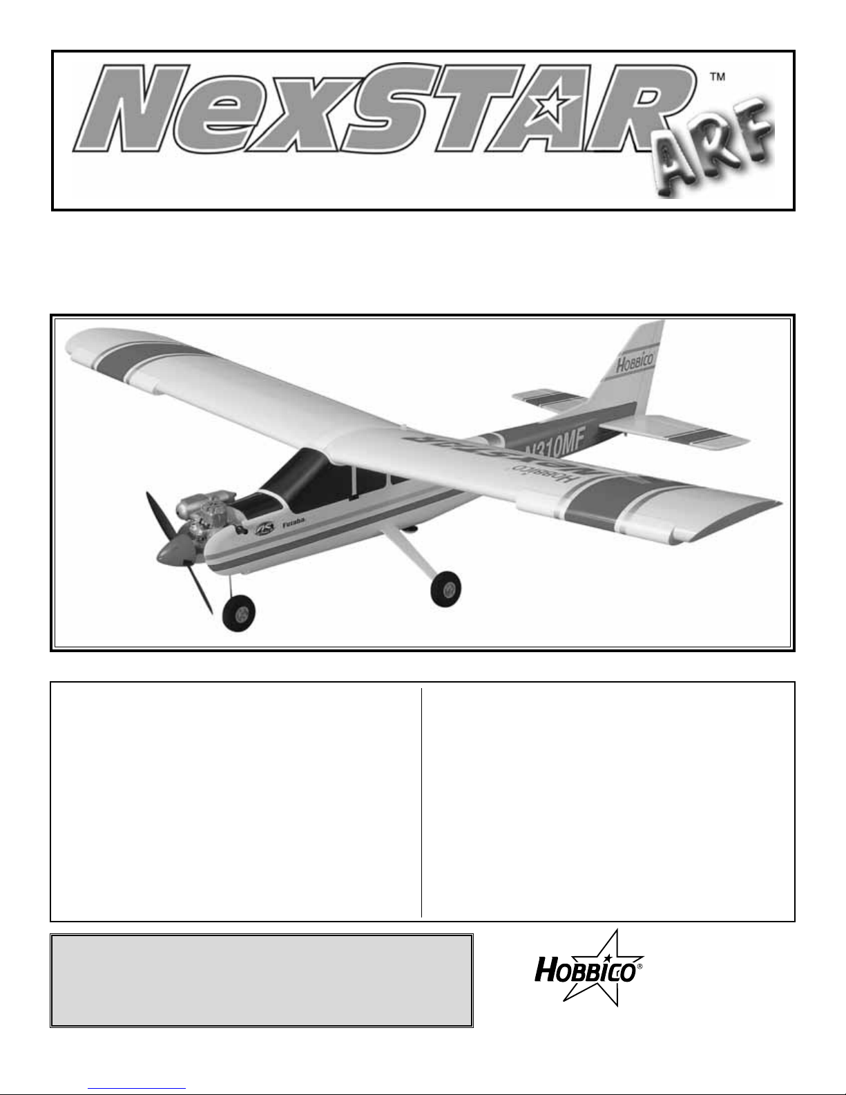
INSTRUCTION MANUAL
ALMOST-READY-TO-FLY RADIO CONTROLLED MODEL AIRPLANE
Wingspan:68-3/4 in [1745mm] Length:56 in [1420mm]
Wing Area: 722 sq in [46.6 dm2]
Weight: 6.25–6.75 lb [2835–3060 g]
Wing Loading: 21 oz/ft2[63 g/dm2] Radio: 4-5 channel
Engine: .46–.50 cu in [7.5–8.2cc] two-stroke
.52–.56 cu in [8.5–9.2cc] four-stroke
Hobbico®guarantees this kit to be free from defects in both
material and workmanship at the date of purchase.This warranty
does not cover any component parts damaged by use or
modification. In no case shall Hobbico’s liability exceed the
original cost of the purchased kit. Further, Hobbico reserves
the right to change or modify this warranty without notice.
In that Hobbico has no control over the final assembly or material
used for final assembly, no liability shall be assumed nor accepted
for any damage resulting from the use by the user of the final
user-assembled product. By the act of using the user-assembled
product, the user accepts all resulting liability.
If the buyer is not prepared to accept the liability associated
with the use of this product, the buyer is advised to return
this kit immediately in new and unused condition to the place
of purchase.
To make a warranty claim, send
the defective part or item to
Hobby Services at this address.
Include a letter stating your name, return shipping address, as
much contact information as possible (daytime telephone number,
fax number , e-mail address), a detailed description of the problem
and a photocopy of the purchase receipt. Upon receipt of the
package the problem will be evaluated as quickly as possible.
WARRANTY
Hobby Services
3002 N. Apollo Dr. Suite 1
Champaign IL 61822
USA
Page 2
INTRODUCTION . . . . . . . . . . . . . . . . . . . . . . . . . . . . . . 2
AMA . . . . . . . . . . . . . . . . . . . . . . . . . . . . . . . . . . . . . . . 2
SAFETY PRECAUTIONS . . . . . . . . . . . . . . . . . . . . . . . 3
DECISIONS YOU MUST MAKE. . . . . . . . . . . . . . . . . . . 3
Radio Equipment. . . . . . . . . . . . . . . . . . . . . . . . . . . . . . 3
Engine Recommendations . . . . . . . . . . . . . . . . . . . . . . . 3
ADDITIONAL ITEMS REQUIRED . . . . . . . . . . . . . . . . . 4
Hardware and Accessories. . . . . . . . . . . . . . . . . . . . . 4
Building Supplies . . . . . . . . . . . . . . . . . . . . . . . . . . . . 4
Optional Supplies and Tools . . . . . . . . . . . . . . . . . . . . 4
IMPORTANT BUILDING NOTES . . . . . . . . . . . . . . . . . . 4
KIT INSPECTION . . . . . . . . . . . . . . . . . . . . . . . . . . . . . 5
ORDERING REPLACEMENT PARTS . . . . . . . . . . . . . . 6
ASSEMBLY. . . . . . . . . . . . . . . . . . . . . . . . . . . . . . . . . . 9
Assemble the Wing. . . . . . . . . . . . . . . . . . . . . . . . . . . 9
Install the Engine . . . . . . . . . . . . . . . . . . . . . . . . . . . 11
Alternate Engine Installation . . . . . . . . . . . . . . . . . . . 13
Landing Gear Installation . . . . . . . . . . . . . . . . . . . . . 14
Install the Tail Surfaces. . . . . . . . . . . . . . . . . . . . . . . 16
Radio Installation . . . . . . . . . . . . . . . . . . . . . . . . . . . 17
GET THE MODEL READY TO FLY . . . . . . . . . . . . . . . 20
Charge the Batteries. . . . . . . . . . . . . . . . . . . . . . . . . 20
Check the Control Directions . . . . . . . . . . . . . . . . . . 20
Check the Control Throws . . . . . . . . . . . . . . . . . . . . . 21
Adjust the Throttle . . . . . . . . . . . . . . . . . . . . . . . . . . 21
Balance the Model . . . . . . . . . . . . . . . . . . . . . . . . . . 22
Identify Your Model . . . . . . . . . . . . . . . . . . . . . . . . . . 22
AMA SAFETY CODE . . . . . . . . . . . . . . . . . . . . . . . . . 23
ENGINE SAFETY PRECAUTIONS . . . . . . . . . . . . . . . 23
CHECK LIST. . . . . . . . . . . . . . . . . . . . . . . . . . . . . . . . 24
FINAL PREPARATIONS . . . . . . . . . . . . . . . . . . . . . . . 24
Gather Your Tools . . . . . . . . . . . . . . . . . . . . . . . . . . . 24
At the Shop Checklist . . . . . . . . . . . . . . . . . . . . . . . . 24
Flight Preparation. . . . . . . . . . . . . . . . . . . . . . . . . . . 25
Check the Frequency . . . . . . . . . . . . . . . . . . . . . . . . 25
Check the Controls. . . . . . . . . . . . . . . . . . . . . . . . . . 25
Range Check the Radio . . . . . . . . . . . . . . . . . . . . . . 25
Fueling the Nexstar ARF. . . . . . . . . . . . . . . . . . . . . . 25
FLYING . . . . . . . . . . . . . . . . . . . . . . . . . . . . . . . . . . . . 26
Taxiing . . . . . . . . . . . . . . . . . . . . . . . . . . . . . . . . . . . 26
Takeoff . . . . . . . . . . . . . . . . . . . . . . . . . . . . . . . . . . . 26
Flight . . . . . . . . . . . . . . . . . . . . . . . . . . . . . . . . . . . . 26
Landing . . . . . . . . . . . . . . . . . . . . . . . . . . . . . . . . . . 26
MAINTENANCE TIPS . . . . . . . . . . . . . . . . . . . . . . . . . 27
AFTER YOU MASTER THE NEXSTAR ARF . . . . . . . . 27
Removing the SpeedBrakes Training Flaps . . . . . . . . 27
Removing the SpinControl Airfoil Extensions. . . . . . . 27
Installing Dual Aileron Servos . . . . . . . . . . . . . . . . . . 27
NEXSTAR SELECT ARF FAQs. . . . . . . . . . . . . . . . . . 30
FIN SKETCH. . . . . . . . . . . . . . . . . . . . . . . . . . . . . . . . 31
Congratulations and thank you for purchasing a Hobbico
NexSTAR ARF, the next generation in Radio Control
Trainers.You have made the right decision by purchasing a
“real” model airplane with the latest in aerodynamic and
assembly technologies. Once assembled and set up, the
NexSTAR will give you many hours of relaxing easy flying.
Under the guidance of an experienced flight instructor, all
you have to do is to concentrate on learning to fly.And after
you have mastered the NexSTAR, your engine and radio
may be transferred to your next model.
For the latest technical updates or manual corrections to the
Hobbico NexSTAR ARF, visit the Hobbico web site at
www.hobbico.com.
Open the “Airplanes” link, and then
select the Hobbico NexSTAR ARF. If there is new technical
information or changes to this model a “tech notice” box will
appear in the upper left corner of the page.
We urge you to join the AMA (Academy of Model
Aeronautics) and a local R/C club. The AMA is the
governing body of model aviation and membership is
required to fly at AMA clubs. Though joining the AMA
provides many benefits, one of the primary reasons to join
is liability protection. Coverage is not limited to flying at
contests or on the club field.It e ven applies to flying at pub lic
demonstrations and air shows. Failure to comply with the
Safety Code (excerpts printed in the back of the manual)
may endanger insurance coverage. Additionally, training
programs and instructors are available at AMA club sites to
help you get started the right way. There are over 2,500
AMA chartered clubs across the countr y. Contact the AMA
at the address or toll-free phone number below:
Academy of Model Aeronautics
5151 East Memorial Drive
Muncie, IN 47302-9252
Tele. (800) 435-9262
Fax (765) 741-0057
Or via the Internet at: http://www.modelaircraft.org
IMPORTANT!!!
Two of the most important things you can do to preserve the
radio controlled aircraft hobby are to avoid flying near fullscale aircraft and avoid flying near or o v er g roups of people .
AMA
INTRODUCTION
TABLE OF CONTENTS
2
Page 3
1. Your Hobbico NexSTAR ARF should not be considered a
toy, but rather a sophisticated, working model that functions
very much like a full-size airplane. Because of its
performance capabilities, the Hobbico NexSTAR ARF, if not
assembled and operated correctly, could possibly cause
injury to yourself or spectators and damage to property.
2. You must assemble the model according to the
instructions. Do not alter or modify the model, as doing so
may result in an unsafe or unflyable model. In a few cases
the instructions may differ slightly from the photos.In those
instances the written instructions should be considered as
correct.
3. You must take time to build straight, true and strong.
4. You must use an R/C radio system that is in first-class
condition, and a correctly sized engine and components
(fuel tank, wheels, etc.) throughout the building process.
5. You must correctly install all R/C and other components
so that the model operates correctly on the ground and in
the air.
6. You must check the operation of the model before every
flight to insure that all equipment is operating and that the
model has remained structurally sound. Be sure to check
clevises or other connectors often and replace them if they
show any signs of wear or fatigue.
7. If you are not an experienced pilot or have not flown this
type of model before, we recommend that you get the
assistance of an experienced pilot in your R/C club for your
first flights.If y ou’ re not a member of a club, your local hobby
shop has information about clubs in your area whose
membership includes experienced pilots.
Remember: Take your time and follow the instructions to
end up with a well-built model that is straight and true.
This is a partial list of items required to finish the Hobbico
NexSTAR ARF that may require planning or decision
making before starting to build.Order numbers are provided
in parentheses.
There are four different w a ys y ou can set up your Ne xSTAR.
The “standard,” most economical setup would be to use four
servos - three servos in the fuselage (for the throttle, rudder
and elevator) and one servo in the wing f or the ailerons.This
requires only a standard, 4-channel radio. The second
option would be to use two servos in the wing (one for each
aileron). Using two aileron servos will increase the roll rate
(for when you are ready to graduate to slightly more
advanced aerobatics).This option will require a Y-harness to
connect the servos, but a standard 4-channel radio ma y still
be used. The third option would be to “mix” the two aileron
servos electronically so the ailerons can be operated as
both ailerons and flaps (flaperons).Doubling the ailerons as
flaps adds another dimension to your flying regimen as you
will be able to execute super-slow landings and flight. The
use of flaperons will require a minimum 5-channel computer
radio for mixing the servos electronically. The fifth option is
for those who have a 5-channel, non-computer radio, but
still desire functional flaps.This will require a sixth servo to
operate the flaps separately. Instructions are provided on
how to cut the ailerons so the inboard portion can be
operated as flaps. All of these options may be done with
standard servos and the regular 500mAh-600mAh battery
pack that came with your radio (special servos or a larger
battery pack are not required).
The recommended engine size range for the Hobbico
NexSTAR ARF is .46 to .50 two-stroke or .52 to .56 four-stroke .
If an engine in the upper end of the size range is used,
remember that this is a model that is intended to fly at scalelike speeds, so throttle management should be practiced.Any
engine in the lower range will be able to fly this model with
authority. Therefore, the engines in the high range are only
recommended for modelers who fly at high altitude.
Engine Recommendations
Radio Equipment
DECISIONS YOU MUST MAKE
NOTE:We, as the kit manuf acturer , provide y ou with a top quality
kit and great instructions, but ultimately the quality of your
finished model depends on how you build it;therefore, we cannot
in any way guarantee the performance of your completed model,
and no representations are expressed or implied as to the
performance or safety of your completed model.
PRO TECT YOUR MODEL,Y OURSELF
& OTHERS...FOLLOW THESE
IMPORTANT SAFETY PRECAUTIONS
3
Page 4
4
In addition to the items listed in the “Decisions Y ou Must
Make” section, the following is a list of hardware and
accessories required to finish the Hobbico NexSTAR ARF.
Order numbers are provided in parentheses.
❏ 6" [150mm] Servo extension (HCAM2701 for Futaba®)
❏ R/C foam rubber (1/4" HCAQ1000, or 1/2" HCAQ1050)
❏ 3/4" to 1" [19 to 25mm] Heavy duty transparent tape
❏ Hook & loop material (1" x 6" [25 x 150mm] GPMQ4480)
❏ Stick-on segmented lead weights (GPMQ4485)
If you decide to install two aileron servos in your wing connected
to the same channel, you will also need the following:
❏ 1 additional standard servo (for a total of 5)
❏ Y-harness (HCAM2751 for Futaba)
❏ 12" [300mm] servo extension (HCAM2711 for Futaba)
❏ 2 Control horns
❏ 4 2-56 x 3/4" screws
❏ 2 Nylon clevises
❏ 2 Nylon faslinks
❏ 2 Silicone retainers
❏ 2 2-56 x 6" pushrods
If you decide to install two aileron servos in your wing
connected to different channels for flaperons, you will need:
❏ 1 additional standard servo for a total of 5
❏ 5-channel computer radio
❏ (2) 12" [300mm] servo extension (HCAM2711 for Futaba)
❏ 6" [150mm] servo extension (HCAM2701 for Futaba)
❏ 2 Control horns
❏ 4 2-56 x 3/4" screws
❏ 2 Nylon clevises
❏ 2 Nylon faslinks
❏ 2 Silicone retainers ❏ 2 2-56 x 6" pushrods
If you decide to install two aileron servos and one flap servo
in your wing, you will need:
❏ All materials listed in one of the options above
❏ 1 additional standard servo for a total of 6
❏ 6" [150mm] servo extension (HCAM2701 for Futaba)
❏ 2 Nylon clevises ❏ 2 Nylon faslinks
❏ 2 Silicone retainers ❏ 2 2-56 x 6" pushrods
In addition to common household tools and hobby tools, this
is the “short list” of the most important items required to
build the Hobbico NexSTAR ARF.
❏ #1 Hobby knife (HCAR0105)
❏ #11 blades (5-pack, HCAR0211)
❏ 3/4" to 1" [19mm to 25mm] Heavy duty transparent tape.
❏ Threadlocker thread locking cement (GPMR6060)
❏ Small metal file (TAMR4046)
Here is a list of optional tools mentioned in the manual that
will help you build the Hobbico NexSTAR ARF.
❏ Top Flite®MonoKote®sealing iron (TOPR2100)
❏ Pliers with wire cutter (HCAR0630)
❏ Switch & Charge Jack Mounting Set (GPMM1000)
❏ Servo horn drill (HCAR0698)
❏ AccuThrow™Deflection Gauge (GPMR2405)
❏ CG Machine™(GPMR2400)
❏ Precision Magnetic Prop Balancer™(TOPQ5700)
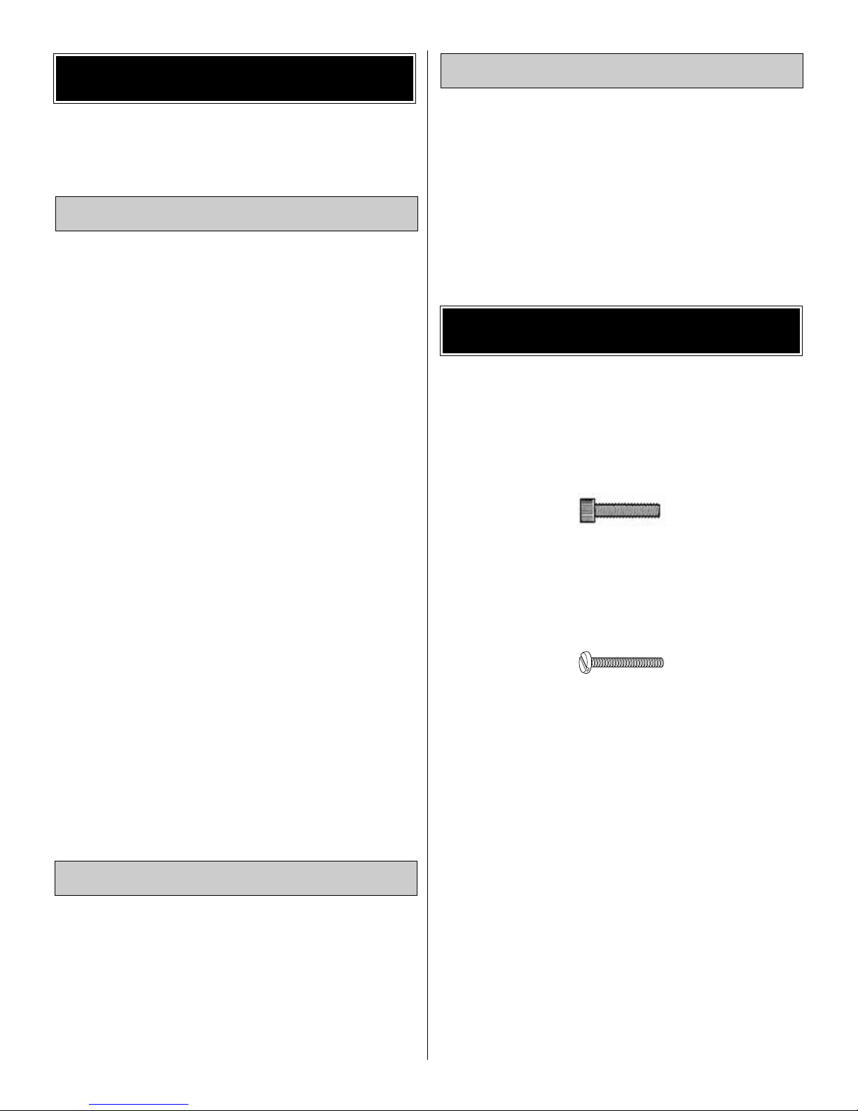
There are two types of screws used in this kit:
Socket Head Cap screws are designated by a number and
a length.
For example #6 x 3/4"
This is a number six screw that is 3/4" long.
Machine screws are designated by a number , threads per
inch, and a length.
For example 4-40 x 3/4"
This is a number four screw that is 3/4" long with forty
threads per inch
.
·
Photos and sketches are placed before the step they
refer to. Frequently you can study photos in following
steps to get another view of the same parts.
·
SHCS is the abbreviation for Socket Head Cap Screw
which is a machine screw with a socket head.
·
The stabilizer and wing incidences and engine thrust
angles have been factory-built into this model. However,
some technically-minded modelers may wish to check
these measurements anyway. To view this information
visit the web site at www.hobbico.com and click on
“Technical Data.” Due to manufacturing tolerances which
will have little or no effect on the way your model will fly,
please expect slight deviations between your model and
the published values.
·
To convert inches to millimeters, multiply inches by
25.4 (25.4mm = 1")
IMPORTANT BUILDING NOTES
Optional Supplies & Tools
Building Supplies
Hardware & Accessories
ADDITIONAL ITEMS REQUIRED
Page 5
Before starting to build, take an inventory of this kit to make sure it is complete, and inspect the parts to make sure they
are of acceptable quality. If any par ts are missing or are not of acceptable quality, or if you need assistance with assembly,
contact Product Support.When reporting defective or missing parts, use the part names exactly as they are written in the
Kit Contents list.
Great Planes Product Support Telephone: (217) 398-8970, ext. 5
3002 N Apollo Drive, Suite 1 Fax: (217) 398-7721
Champaign, IL 61822 E-mail: airsupport@greatplanes.com
KIT INSPECTION
5
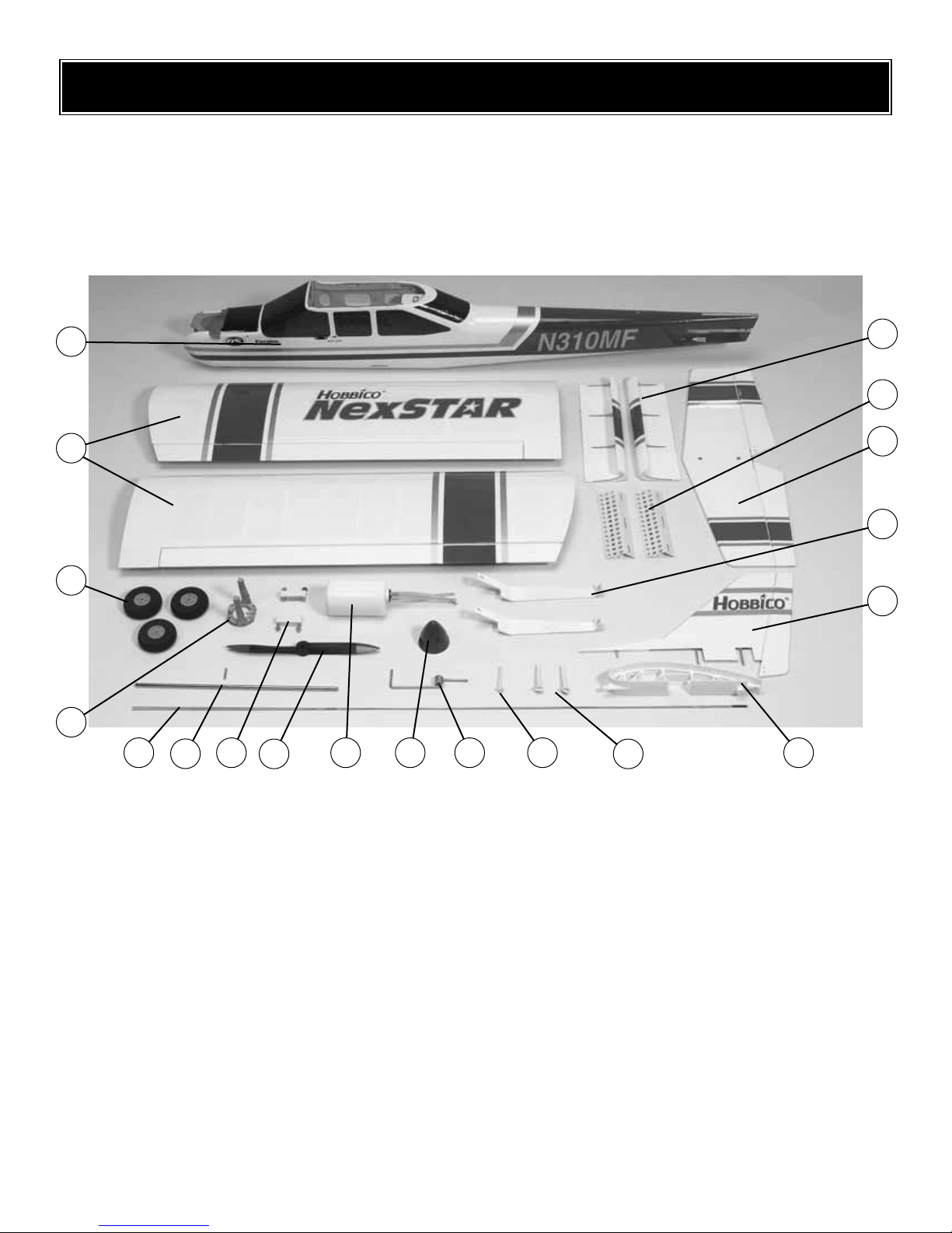
Parts photographed
1. Fuselage
2.Wings
3.Wheels
4. Engine mount
5. 2mm Control rods
6.Wing joiner rods
7. IsoSmooth engine mount
8. 11" x 5" [280 x 127mm] NexSTAR nylon propeller
9. Assembled fuel tank
10. 2-1/2" [64mm] Spinner
11. Nose landing gear
12. 1/4-20 x 2" [51mm] Nylon wing bolt
13. EasyAlign tail bolts
14. CenterCore wing Joiner
15. Fin/Rudder
16. Aluminum main landing gear
17. Stab/elevator
18. SpeedBrakes training flaps
19. Leading Edge Airfoil Extensions
Parts not photographed
4 Nylon clevis
4 Nylon Faslinks
4 Silicone retainers
2 Nylon Aileron Control Horns
4 #4 x 3/4" [19mm] Wood screws
6 #4 x 5/16" [8mm] Machine screws
4 4mm x 3/4" [19mm] Machine screws
4 4mm x 1-1/8" [30mm] Machine screws
4 4mm Nuts
4 4mm Washers
4 4mm Lock washers
2 Nylon control horns
4 #2 x 1/2" [12mm] Wood screws
2 Screw-lock pushrod connector
1
2
3
4
6
5 7
8
9 10 11 12
16
13
14
15
19
18
17
Page 6
Replacement parts for the Hobbico NexSTAR ARF are
available using the order n umbers in the Replacement Parts
List that follows.The fastest, most economical service can be
provided by your hobby dealer or mail-order company.
To locate a hobby dealer, visit the Hobbico web site at
www.hobbico.com. Choose “Where to Buy” at the bottom
of the menu on the left side of the page. Follow the
instructions provided on the page to locate a U.S., Canadian
or International dealer. If a hobby shop is not available,
replacement parts may also be ordered from Tower
Hobbies®at www.towerhobbies.com, or by calling toll free
(800) 637-6050.
Parts may also be ordered directly from Hobby Services by
calling (217) 398-0007, or via facsimile at (217) 398-7721,
but full retail prices and shipping and handling charges will
apply. Illinois and Nevada residents will also be charged
sales tax. If ordering via fax, include a Visa®or MasterCard
®
number and expiration date for payment.
Mail parts orders and payments by personal check to:
Hobby Services
3002 N Apollo Drive, Suite 1
Champaign IL 61822
Be certain to specify the order number exactly as listed in
the Replacement Parts List. Payment by credit card or
personal check only; no C.O.D.
If additional assistance is required for any reason contact
Product Support by e-mail at:
productsupport@greatplanes.com
or by telephone at (217) 398-8970.
REPLACEMENT PARTS LIST
Order
Number Description How to purchase
HCAA3736 . . Wing kit . . . . . . . . . . . .Local hobby dealer
HCAA3737 . . Spin-Control Airfoil
Extensions/Speed
Brakes . . . . . . . . . . . . .Local hobby dealer
HCAA3738 . . Fuselage kit
w/o engine mount . . . .Local hobby dealer
HCAA3739 . . Engine mount . . . . . . .Local hobby dealer
HCAA3740 . . IsoSmooth
engine mount . . . . . . . .Local hobby dealer
HCAA3741 . . Tail set . . . . . . . . . . . . .Local hobby dealer
HCAA3742 . . Landing gear . . . . . . . .Local hobby dealer
HCAA3743 . . Decal set . . . . . . . . . . .Local hobby dealer
HCAA3744 . . NexSTAR nylon
11 x 5 prop . . . . . . . . .Local hobby dealer
Missing pieces . .Contact Product Suppor t
Instruction manualContact Product Suppor t
Full-size plans . . . . . . . . . . . .Not available
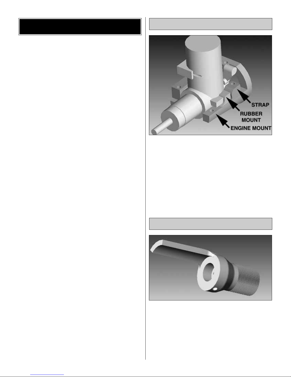
This new mount may look like other aluminum engine
mounts, but make no mistake, it is unique. The engine
mounting lugs are installed in rubber boots that absorb
engine vibration to protect your airframe and radio
components, increasing their life span. The IsoSmooth
engine mount works so well that you should check your
propeller for nicks or cracks, because with this mount, you
won't feel a thing.
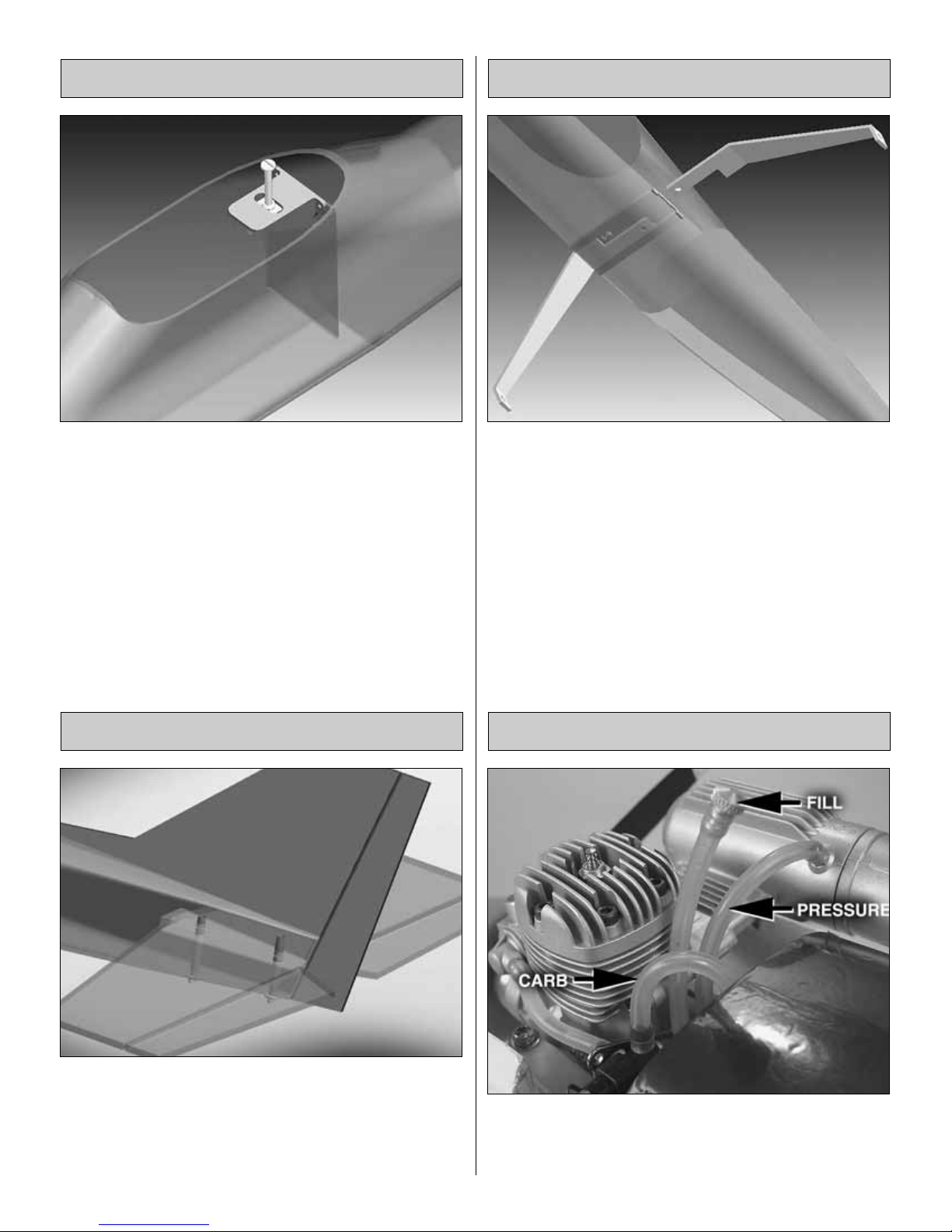
The NexSTAR ARF is equipped with a high speed needle
valve extender/limiter to make engine adjustments safer
and easier.The extender/limiter has been set at the factory
to limit the movement of the high speed needle so that it
cannot be adjusted out of the optimum range.This way the
engine will always work at its peak performance without the
worry of engine damage. The extender/limiter will allow the
needle to be set from the leanest desired setting for safe
operation (fully clockwise) to the richest desired setting for
break in (fully counterclockwise).
Extender/Limiter
IsoSmooth™Engine Mount
ORDERING REPLACEMENT PARTS
6
Page 7
The wings of most trainers are mounted with rubber bands.
This allows for some flexibility in case of a hard landing.
Rubber bands work well, but they are just plain ugly and a
mess. The PivotFlex Wing Mounting System combines the
looks of a bolt-on system with the flexibility of rubber bands.
The new system allows the wing to move under sudden
loads (such as a wing tip hitting the ground) and will release
the wing from the airplane under extreme loads such as a
crash—all that while looking great.
The EasyAlign Tail Mounting System aligns the stabilizer
with the fuselage and fin while tightening the tail bolts.The
tail bolts slide into blocks in the fuselage under the
stabilizer. As the tail bolts are tightened, both the fin and
stab are aligned and secured while strengthening the aft
area of the fuselage.No tools are necessary for installation.
To speed and simplify assembly, the Hobbico NexSTAR
ARF comes equipped with the SnapGear Landing Gear.
This new gear offers effortless and tool less main landing
gear installation. It takes only a few seconds to install the
landing gear and it can also be removed from the fuselage
in seconds.
The Hobbico NexSTAR ARF uses a three-line fuel line
system to simplify fueling and de-fueling.
Three-Line Fuel System
SnapGear™Landing Gear
EasyAlign™Tail Mounting System
PivotFlex™Wing Mounting System
7
Page 8
The CenterCore wing rib is a nylon part that comes
preinstalled onto one of the wing halves.It performs several
functions: it aligns the two wing halves; it is a mount for the
aileron servo;the incorporated wing dowel holds the wing in
place; and it holds and aligns the wing bolt to the PivotFle x
™
Wing Mounting System. Joining the wing halves and wing
installation on the fuselage has never been easier.
These are the extensions that are installed at the leading
edge near the tips of the wings. These extensions were
developed by NASA (National Aeronautics and Space
Administration) to help light airplanes prevent stalls and
spins during landing approaches. That is exactly what they
do for your NexSTAR ARF. They slow down the airplane,
increase its stall resistance and prevent it from spinning, all
desired characteristics of a trainer airplane. The wing
extensions can be remov ed after you become proficient with
the NexSTAR ARF, for faster, more aerobatic performance.
The SpeedBrakes Training Flaps were designed to allow your
NexSTAR ARF to fly slower, reduce top speed and shorten
the landing approach. Thanks to these flaps, your NexSTAR
ARF will bleed off speed quickly when the throttle is reduced
so that long landing approaches are not necessary.
Additionally, the top speed is considerably reduced to make
the airplane easier to handle. These SpeedBrakes can also
be removed after acquiring some experience with the
airplane for faster, more aerobatic performance.
SpeedBrakes™Training Flaps
SpinControl™Airfoil Extensions
CenterCore™Wing Rib
8
Page 9
For this section you will need:
Note: The following steps show the assembly of the wing
using one aileron servo. For a 2-servo installation, please
refer to the section “After You Master the NexSTAR in its
Original Form” on page 27.
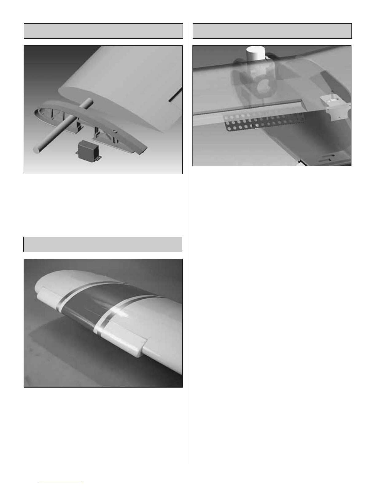
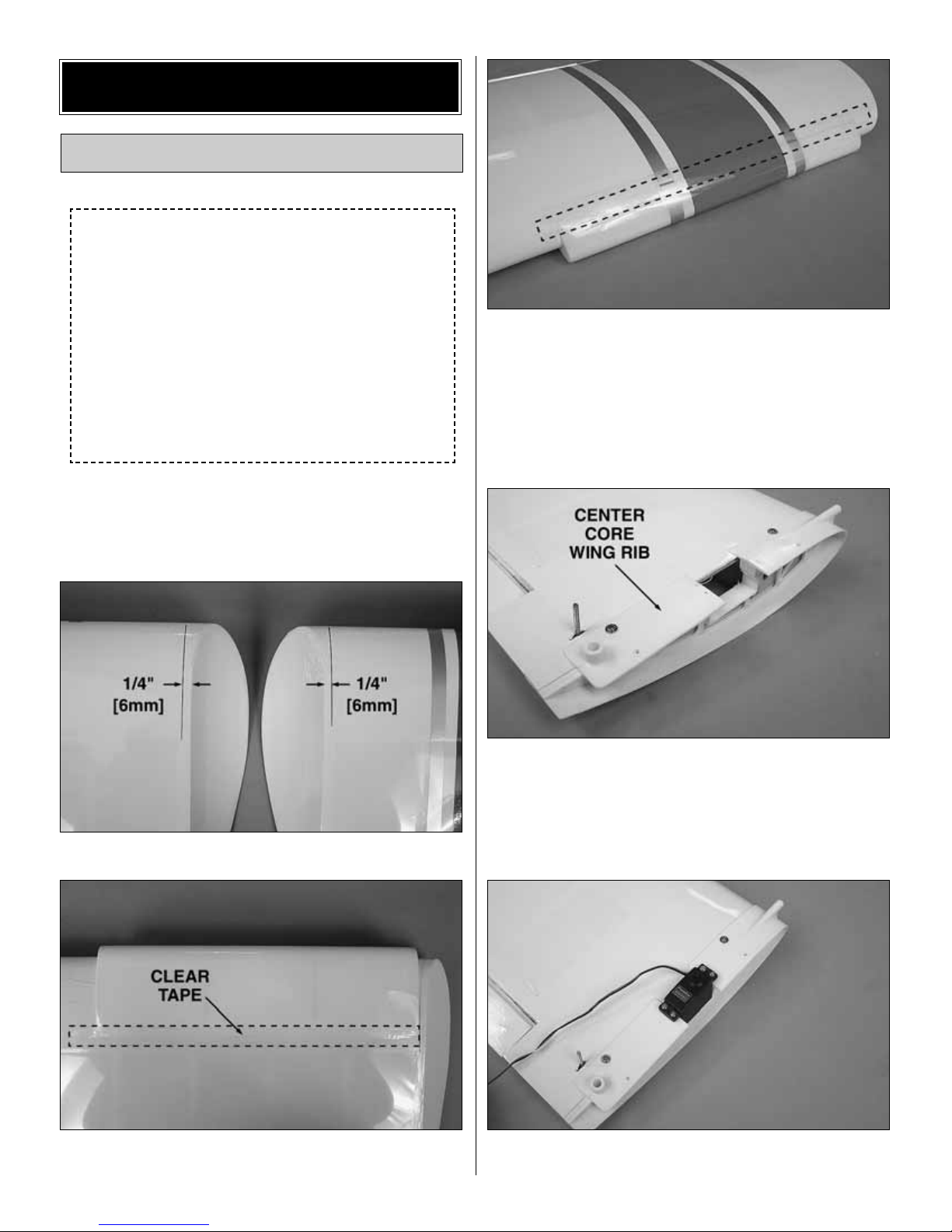
❏ 1.Mark a line on the bottom of the wings 1/4" [6mm] from
the end of the tips.
❏ 2. Install the Airfoil Extensions on both wings as shown
using 3/4" to 1" [19 to 25mm] heavy duty clear plastic tape.
❏ 3.Locate the Spin-Control Airfoil Extension decals on the
decal sheet and apply them to both wings following the
scheme on the top of both wings. Also apply the NexSTAR
decal on the top of the left or right wing.
❏ 4. Install the CenterCore wing rib on the right wing using
two #4 x 3/4" [19mm] screws.
❏ 5. Install the aileron ser vo as shown using the hardware
supplied by the manufacturer.
1 Left wing
1 Right wing
2 Airfoil extensions
2 SpeedBrakes training
flaps
1 CenterCore wing rib
1 Steel wing rod
1 Anti-Rotation steel pin
2 Nylon clevises
2 Nylon faslinks
2 Silicone retainers
2 2-56 X 6" [150mm]
pushrods
2 Nylon horns
4 #4 x 3/4" [19mm]
Wood screws
6 #4 x 5/16" [8mm]
Wood screws
1 Standard servo
1 Phillips screwdriver
3/4" to 1" [19 to
25mm] Heavy duty
clear plastic tape
Assemble the Wing
ASSEMBLY
9
Page 10
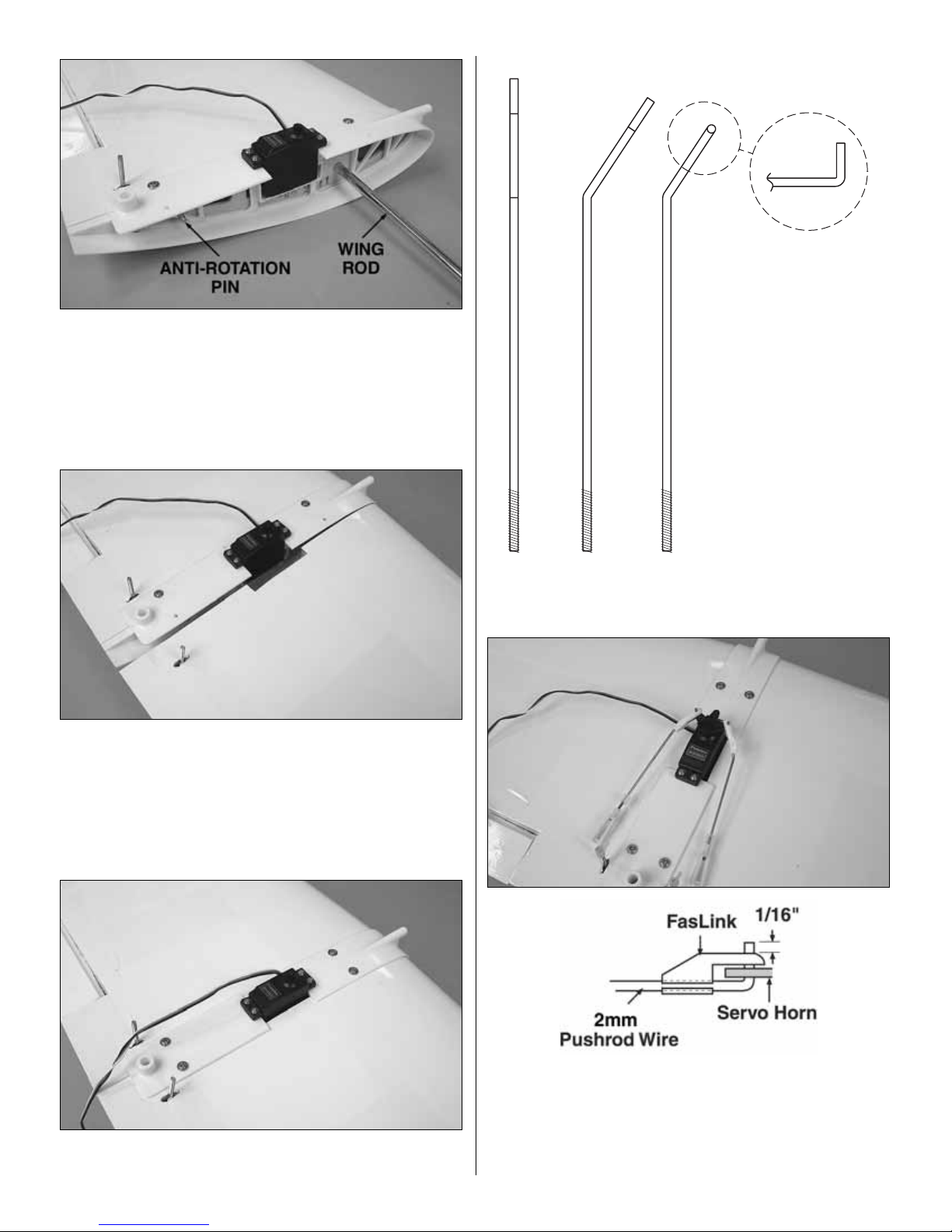
❏ 6. Install the wing rod and the anti-rotation pin into the
right wing.
❏ 7.Carefully slide the left wing all the way onto the rod and
into the CenterCore wing rib until it stops.
❏ 8.Use tw o more #4 x 3/4" [19mm] screws to hold the two
wing halves together.
❏ 9. Cut and bend a 2mm x 6"[150mm] pushrod to match
the sketch above. Make a left and a right pushrod.
❏ 10. Cut a servo arm as shown above and use a Hobbico
Servo Horn Drill (or a #48 or 5/64" [2mm] drill bit) to enlarge
the servo arm holes. Install the arm on the servo. Install a
clevis and a clevis retainer on the threaded end of the
pushrods.Slide the unthreaded end of the pushrod into y our
servo arms and install Faslinks to secure them.
10
Page 11

❏ 11. Install the nylon horns on the aileron torque rods.
Thread them in until the bottom of the horn is about 1/2"
[12mm] from the wing surface. Connect the clevises to the
horns. Slip the clevis retainers over the clevises.
❏ 12. Locate one of the SpeedBrakes Training flaps. There
are three small holes drilled into the trailing edge of the wing
near the center.Install the flap to the wing using three #4 x
1/4" [6mm] screws. The inner end of the flap should align
with the end of the aileron.
❏ 13. Install the other flap onto the other wing using three
more #4 x 1/4" [6mm] screws.The wing is now complete.
Note: Install the leading edge extensions and the flaps
for your initial flights. The airplane has been designed
around them and it performs better as a trainer with them
installed. Never attempt to fly the airplane for the first time
without them or with just one of the devices as the model will
be difficult to trim.Do not let anyone’s opinion get in the way .
Install both these devices for your initial flights. If after
a few flights you decide to remove the extensions or flaps,
then read the section “After You Master the NexSTAR in its
Original Form” on page 27.
For this section you will need:
❏ 1. Slide the fuel tank into the fuel tank compartment.
Make sure the fuel tubing comes out through the hole in the
firewall. Slide the fuel tank in until the neck of the fuel tank
comes out the firewall as shown above. Use a Phillips
screwdriver to tighten the fuel tank screw and secure the
tank in place.
❏ 2.Use four 4mm x 20mm machine screws and four 4mm
washers to install the engine mount as shown above. Use
Great Planes Thread Locking Compound on the machine
screws before you tighten them.
Engine
Fuel tank
Metal engine mount
4 4mm x 20mm Engine
mount machine
screws
IsoSmooth complete
engine mount
4 4mm x 30mm
IsoSmooth engine
mount screws
4 4mm Nuts
8 4mm Washers
4 4mm Lock washers
2-56 x 17-1/2"
[445mm] pushrod.
Phillips screwdriver
Install the Engine
11
Page 12

❏ 3. Install the IsoSmooth rubber boots on the engine
mounting lugs. The IsoSmooth rubber boots have been
designed to fit most .46 size engines. If the boots do not fit
your engine, then you will have to use an alternate method
to install your engine (see below).
❏ 4. Use four 4mm x 30mm machine screws, four 4mm
washers, four 4mm loc k w ashers and f our 4mm n uts to secure
the engine with the IsoSmooth nylon bracket on the engine
mount. Use Great Planes Thread Locking Compound on the
screws to prevent them from coming loose with vibration.
❏ 5. Install a clevis and a clevis retainer on the threaded
end of the 17-1/2" [445mm] pushrod. Bend the pushrod
slightly as shown above to clear the engine mounting bolts.
❏ 6.Slide the pushrod into the guide tube and then connect
the clevis to the carburetor arm as shown above. Slip the
clevis retainer onto the clevis.
❏ 7. Mount the muffler on the engine following your engine
manufacturer’ s recommendations .Also, install the glow plug
and connect the fuel lines to the engine.The red line goes
to the pressure tap on the muffler, the g reen line goes to the
needle valve, and the blue line is the fill line. Cap the fill line
with the aluminum plug supplied.
12
Page 13

❏ 8. Install the spinner backplate, propeller, propeller
washer and propeller nut to the engine. Align the propeller
with the marks on the spinner backplate and then tighten
the propeller nut securely.
❏ 9. Fit the spinner cone to the back plate. Then, use a
Phillips screwdriver to tighten the spinner screws snugly, but
not over-tight.
Selecting the correct propeller for an
airplane is very important. Your
NexSTAR ARF comes equipped with
a specially-designed nylon 11x5
propeller (HCAA3744) with painted
tips. The painted tips are a safety
feature that will help you see the
propeller arc as the engine is running.
Propeller (HCAA3744)
Keep away from the propeller while the engine is running.
The engine size used on the NexSTAR ARF is powerful
enough to cause damage if anything (including you) gets in
the propeller arc.The propeller is made out of flexible nylon
so that it won’t break on light contact with the runway or
weeds. If the propeller ever gets in contact with anything
while the engine is running, inspect it before running it
again. Check for cracks, scuffled tips or unbalanced blades.
If necessary, replace the propeller. The Hobbico NexSTAR
ARF was designed around an 11x5 propeller for best
performance. The 11x5 propeller helps keep the airplane
speed down at full throttle; it increases takeoff performance
on any surface, including tall grass; and it acts as a brake
when the nose is pointed down. Should you ever need to
replace the propeller, replace it with the same or similar
11x5 propeller.There is no benefit to using a larger propeller
or one with more pitch.
Carefully balance your propeller and spare propellers
before you fly. An unbalanced prop can be the single most
significant cause of vibration that can damage your model.
We use a Top Flite Precision Magnetic Prop Balancer
™
(TOPQ5700) in the workshop and keep a Great Planes
Fingertip Prop Balancer (GPMQ5000) in our flight box.
Your engine is now installed.
❏ 1. If the engine rubber boots do not fit the engine of your
choice, you will have to install the engine as shown above
using two metal straps (included), four 4mm x 30mm, four
4mm nuts, four 4mm washers and four 4mm lock washers.
Alternate Engine Installation
13
Page 14

For this section you will need:
❏ 1.File two flat spots on the nose gear wire as shown above.
❏ 2.Install the nylon nose gear bracket to the firewall using
two 4 x 20mm machine screws and two 4mm flat washers.
Use Great Planes Thread Locking Compound on the
machine screws before tightening them.
❏ 3. Place a wheel collar in the nylon steering arm as
shown.Use the 4 x 6mm [1/4"] machine scre w on the wheel
collar. Slide the steering pushrod’s “Z” bend through the
hole in the steering arm.
❏ 4. Slide the steering arm’s pushrod into its guide tube.
Install the nose landing gear leg through the nylon bracket,
the steering arm and then the engine mount. Tighten the
screw on the steering arm.
❏ 5. Install the nose wheel on the nose gear wire. Use two
wheel collars, one on each side of the wheel, to align it and
secure it in place.Apply some Great Planes Thread Locking
Compound to the screws.
❏ 6. Install a wheel axle on each aluminum landing gear
leg. File a flat spot near the end of the axle.
❏ 7. Install a wheel on each of the axles and then secure
them with a wheel collar. Use some Great Planes Thread
Locking Compound on the screws.
Nose gear wire
Aluminum main gear
(2 parts)
3 Wheels
2 Landing gear axles
1 Nylon nose gear
bracket
2 4mm x 19mm
Machine screws
2 4mm Washers
1 Steering arm
5 4mm Wheel collars
1 Steering pushrod
Phillips screwdriver
Metal file
Landing Gear Installation
14
Page 15

❏ 8.Slide one of the main landing gear legs into the landing
gear slot as shown above. Push it in until you hear a “click”
or until it does not slide in any more.Note:The two landing
gear legs are identical, so it does not matter which one you
install on the left side or right side of the airplane.
❏ 9. Install the other landing gear leg on the other side of
the fuselage the same way. Once they are both installed,
apply a light force to pull them out.You should not be able
to pull them out. If they do pull out, then push them back in
again until they are secured properly. Note:The legs may fit
a little loose inside the pocket.This is normal as long as you
are not able to pull the landing gear legs out.
Landing gear installation is complete.
Note: Should you ever need to remove the landing gear
from the fuselage, insert a screwdriver into the hole under
the fuselage farther from the leg you want to remove. Apply
light pressure to the tab inside the hole and pull the landing
gear leg out. Once the tab is moved, the screwdriver must
be removed to allow the leg to come all the way out. Do the
same with the other landing gear leg.
Note: If your landing gear does not insert easily in the
fuselage or it does not lock in, clean up any glue or paint
blobs that may be on the gear or in the mounting
mechanism. Inser t the gear again and make sure it does
lock in.
Note: If your landing gear legs spread after a hard landing,
remove the legs from the airplane and bend them back to
the correct position with a vise. Do not try to straighten the
legs while installed in the airplane as that may damage the
Snap Gear Landing Gear mechanism.
15
Page 16

For this section you will need:
Note: It is recommended that you apply the fuselage, stab
and fin decals at this point. It is easier to do when the parts
are all apart.
❏ 1. Install a nylon clevis and a clevis retainer on the two
steel pushrods.Slide both pushrods into their guide tubes in
the tail of the airplane.
❏ 2.Position a nylon control horn on the bottom of the right
elevator all the w ay against its inner edge.Mark the location
of the control horn mounting holes. Drill through the mar ks
with a 1/16" [1.6mm] drill bit. Secure the control horn to the
elevator using two #2 x 1/2" [12mm] screws.
❏ 3. Position a nylon control horn on the rudder as shown
about 1/8" [3mm] from the bottom edge.Note that one of the
edges of the control horn is aligned with the hinge line of the
rudder. Mark the location of the control horn mounting
holes. Drill through the marks with a 1/16" [1.6mm] drill bit.
Secure the control horn to the rudder using two #2 x 1/2"
[12mm] screws.
❏ 4. Insert the horizontal stabilizer into the stab slot as
shown above. Insert the two nylon fin tail bolts half-way into
the bottom fuselage and into the stab to hold it in place.
❏ 5. Place the fin over the sketch found on the last page of
the manual and make sure the fin rods are bent at the same
angle as the ones shown on the sketch.This step is cr itical
to make the fin installation easier.
Stabilizer
Fin
2 Control horns
4 #2 x 1/2 [12mm]
Screws
2 Nylon tail bolts
2 Nylon clevises
2 Silicone clevis
retainers
2 2mm Steel pushrods
Phillips screwdriver
Install the Tail Surfaces
16
Page 17

❏ 6. Insert the ver tical stabilizer into the fin slot as shown
above. During installation, make sure the rudder control
horn is below the elevator so that it does not interf ere.It may
take a little maneuvering to slide the aft fin rod in front of the
wood block in the fuselage slot.
❏ 7.Tighten the bolts until they fit snugly against the bottom
of the fuselage. Note: Over tightening these bolts will
damage the nylon threads and may cause in flight failure.
Do not over tighten these bolts.
❏ 5.Connect both the ele v ator and rudder pushrod cle vises
to their control horns.Use the second hole from the outer tip
of the control horn for both of them. This will allow you to
obtain the recommended throws. Slide the silicone clevis
keeper over the clevis.
Tail assembly is complete.
For this section you will need:
❏ 1. Install the elevator, rudder and throttle servos in the
fuselage servo tray as shown above using the hardware
supplied by the radio manufacturer.
3 Standard size servos
1 6" [150mm] Extension
servo mounting
Hardware
2 Faslinks
2 Complete screw-lock
pushrod connectors
Foam sheet
Pliers
Phillips screwdriver
Radio Installation
17
Page 18

❏ 2. Wrap the receiver and the battery with foam and then
install them on the radio tray. Use the hook and loop
material supplied to secure them in place.
❏ 3. Install a 6" [150mm] extension on the receiver’s aileron
channel. Connect the radio switch to the receiver and the
battery .Use heat shrink tubing to secure the battery connection.
Install the radio tray in the fuselage with two #4 x 3/8" [9mm]
wood screws.Connect all the servos to the receiver.
❏ 4.Install the radio switch to the fuselage on the opposite side
of the muffler.If you desire, you can also install a charge jack.
This will allow you to charge the batteries or check their voltage
at the field without taking off the wing.In the instruction manual
airplane we installed an Ernst charge jack.
❏ 5.Route the receiver antenna under the servo tr a y. Install
a retainer on it and then slip it through the plastic guide tube
in the middle until it exits at the aft end of the airplane.
Secure the antenna with tape. Tur n on the transmitter and
then the receiver and center all the trims on the transmitter .
❏ 6. Cut the elevator, throttle and the rudder servo arms as
shown. Install a Screw-Lock Pushrod Connector on the throttle
and the rudder arm as shown above.Note the holes where the
Screw-Lock Pushrod Connectors are connected.
18
Page 19

❏ 7. Slide the steering pushrod and the throttle pushrod
through the Screw-Lock Pushrod Connectors. Install the
servo arms centered on the servos and center the rudder
and elevators.
❏ 8. Mark the elevator and rudder pushrods where they
meet with the servo arm holes. Bend the pushrods 90
degrees up at the mark.Enlarge the servo arm holes where
the pushrods will be connected with a Hobbico Servo Horn
Drill (or a #48 or 5/64" [2mm] drill bit.) Slide pushrods into
the servo arms. Note the ser vo arm holes used to connect
the elevator and rudder pushrod.
❏ 9. Install a Faslink on the elevator and rudder pushrods
to secure them to the servo arms. Cut off the excess wire.
❏ 10. Center the nose wheel and tighten the steering’s
Screw-Lock Pushrod Connector. Move the throttle stick to
full power and then fully open the carburetor by pushing on
the throttle pushrod. Make sure the throttle servo is working
in the correct direction and reverse it if necessary. Install the
throttle’s servo arm as shown and tighten the Screw-Lock
Pushrod Connector. Cut any excess wire and replace the
servo arm screws.
❏ 11. Remove the aileron servo arm and connect the
aileron servo to the receiver aileron servo extension.Center
the transmitter trims and reinstall the aileron servo arm
making sure it is centered. Replace the ser vo arm screw.
Use thread locking compound on the screws.
Note: The control surfaces should be centered when the
trims in your transmitter are centered. Minor adjustments
can be made by screwing or unscrewing the nylon clevises
on the control surfaces.
19
Page 20

Now the plane is assembled, but there are a few things that
must be done before it will be ready to fly.You must carefully
perform all of the following Setup procedures. If possible,
have your flight instructor assist you.
If you have not yet charged the batteries, you may still
proceed. However, as the batteries have not yet been fully
charged, they may not provide enough power to make it all
the way through the setup procedures. If the batteries quit
working, set your tools aside and charge the batteries as
described in the instruction manual for the radio control
system that you are using.
Follow the battery charging instructions that came with your
radio control system to charge the batteries. You should
always charge your transmitter and receiver batteries the
night before you go flying, and at other times as
recommended by the radio manufacturer.
❏ 1. Move the right control stick on the transmitter to the
right as shown in the photo. Observe the direction the
ailerons move.
The right aileron should move up and the left aileron should
move down.Moving the control stick to the left should make
the ailerons move the opposite way. If the ailerons do not
respond as described, reverse the direction using the
reversing switch for the aileron on the face of the
transmitter. If necessary, refer to the instructions in your
radio instruction manual to identify and operate the
reversing switch.
❏ 2. Move the right stick down and observe the direction the
elevator moves.
Moving the right stick down should make the elevator move
up. Note that moving the elevator stick down moves the
elevator up (which, in flight, pushes the tail down, thus
increasing the angle of the wing and making the model
climb).The best way to keep this in mind is to think in terms
of a pilot in an airplane. He pulls the control stick back to
“pull up” the nose of the plane.
Check Control Direction
CAUTION: Unless the instructions that came with your
radio system state differently, the initial charge on new
transmitter and receiver batteries should be done for 15
hours using the slow-charger that came with the radio
system.This will “condition” the batteries so that the next
charge may be done using the fast-charger of y our choice.
If the initial charge is done with a fast-charger, the
batteries may not reach their full capacity and you may be
flying with batteries that are only partially charged.
Charge the Batteries
GET THE MODEL READY TO FLY
20
Page 21

❏ 3. Move the left stick to the right and obser ve the rudder.
Moving the stick to the right should make the rudder (and
the nose wheel) move to the right. If necessary, use the
reversing switches on the transmitter to make the rudder
respond in the correct direction.
The next procedure is to make sure the controls move the
correct amount.The control throws are a measure of how far
the flight controls (ailerons, elev ator and rudder) move .If the
controls move too much, the plane will respond too quickly
and be difficult to control. If the controls do not move
enough, it may not be possible to recover from adverse
situations or to level out for landing. Due to the great effect
the control throws have on the w ay a model flies, the control
throws must be checked.
Control Throws Chart
The throttle is to be set up so that when the throttle stick is
all the way down, and the throttle trim le ver is all the way up ,
the carburetor will be nearly, but not fully closed and the
engine will idle at a low RPM. This will keep the engine
running when the throttle stick is pulled all the way down
(toward you) for landing. When it is time to shut the engine
off after landing, move the trim lever down to close the
carburetor the rest of the way.
Here’s how to set up the carburetor…
❏ 1.With the transmitter and receiver on, move the throttle
trim lever and the throttle stick all the way down.
❏ 2.Observe the opening in the carb uretor.If the carburetor is
fully closed, proceed to step 3. If the carburetor is nearly, but
not fully closed, loosen the screw on the screw-lock connector
on the throttle servo arm and move the pushrod back until the
carburetor is closed.Securely tighten the screw.
❏ 3.Move the throttle trim lever all the wa y up, but leave the
throttle stick all the way do wn.Now the carburetor should be
partially open (about 1/32" to 1/16" [1 to 1.5mm]).
Adjust the Throttle
UP DOWN
Ailerons 1/2" [13mm] 3/8" [9mm]
Elevator 1/2" [13mm] 1/2" [13mm]
RIGHT LEFT
Rudder 3/4" [19mm] 3/4" [19mm]
Check the Control Throws
21
Page 22

❏ 4.Move the throttle stick on the transmitter all the wa y up .
The carburetor should be fully open.
❏ 5. If you are not able to achieve these settings, more or
less movement may be required from the throttle pushrod.
The same as the control surface throws, this is done by
relocating the clevis on the carburetor arm to the other hole,
or by relocating the pushrod connector on the servo arm to
another hole.
DO NOT DISREGARD THIS STEP!
This important step is also referred to as “checking the
C.G.” (center of gravity).Simply stated, the center of gravity
is the point at which the model balances when lifted under
the wing. If the C.G. is too far forward, the model will be
“nose-heavy” and could be difficult to takeoff and land and
lose some of its self-correcting tendencies.If the C.G.is too
far aft, the model will be “tail-hea vy”and the controls may be
too sensitive, making the model too difficult to control—
especially for an inexperienced pilot! Follow the instructions
to balance the model correctly, thus giving you the greatest
chances for success!
❏ 1. There is a decal with two black lines on the underside
of the wing.Those mark the forward and aft CG limit for the
NexSTAR ARF.The forw ard CG limit is 3-3/16" [81mm].The
aft CG limit is 3-9/16" [90mm] from the LE.
❏ 2. Make certain the model is in “ready-to-fly” condition
with all components mounted and installed (propeller,
spinner, landing gear, etc.). The fuel tank must be empty.
❏ 3. Mount the wing to the fuselage with the nylon wing
bolt. Lift the model on both sides of the fuselage with your
fingertips between the two lines on the bottom of the wing.
❏ 4. If the fuselage is level when lifting the model with your
fingers anywhere between the lines, the C.G. is correct.
Proceed to the checklist in the following section.If you cannot
find a spot between the two lines where the airplane balances,
then either one of the following will happen: If the tail drops
when lifting the model, the plane is tail heavy and will require
nose weight to balance. If the nose drops, the plane is nose
heavy and will require tail weight. Do not be concerned if your
model requires a few ounces of nose or tail weight. Almost all
models require additional weight to balance and fly correctly!
If additional weight is required to balance the plane, purchase Great
Planes®Self Adhesive Lead Weights (GPMQ4485).The weight is
segmented in 1/4 oz.increments and is easy to work with.If adding
weight to the tail, attach it to the left side of the fuselage (opposite
the muffler) under the stab.If adding weight to the nose, attach it to
the inside of the fuselage side next to the engine.
❏ 5. If you found it necessary to add weight, recheck the
C.G. after doing so.
Whether you fly at an R/C club or somewhere on your o wn, you
should have your name , telephone n umber, address and AMA
number on or in your model so it can be identified and returned
in case it lands somewhere awa y from the flying site.Fill out the
I.D .tag found in the back of the manual and use spray adhesiv e
or tape to stick it in the model.
Identify your Model
Balance the Model
22
Page 23

Read and abide by the following e xcerpts from the Academy
of Model Aeronautics Safety Code.For the complete Safety
Code refer to
Model Aviation
magazine, the AMA web site
or the Code that came with your AMA license.
GENERAL
1. I will not fly my model aircraft in sanctioned events, air
shows, or model flying demonstrations until it has been
proven to be airworthy by having been previously,
successfully flight tested.
2. I will not fly my model aircraft higher than approximately
400 feet within 3 miles of an airport without notifying the
airpor t operator. I will give right-of-way and avoid flying in
the proximity of full-scale aircraft. Where necessary, an
observer shall be utilized to supervise flying to avoid having
models fly in the proximity of full-scale aircraft.
3.Where established, I will abide by the safety rules for the
flying site I use, and I will not willfully and deliberately fly my
models in a careless, reckless and/or dangerous manner.
5. I will not fly my model unless it is identified with my name
and address or AMA number, on or in the model.Note:This
does not apply to models while being flown indoors.
7. I will not operate models with pyrotechnics (any device
that explodes, burns, or propels a projectile of any kind).
RADIO CONTROL
1. I will have completed a successful radio equipment ground
check before the first flight of a new or repaired model.
2. I will not fly my model aircraft in the presence of
spectators until I become a qualified flier, unless assisted b y
an experienced helper.
3. At all flying sites a straight or curved line(s) must be
established in front of which all flying takes place with the
other side for spectators.Only personnel involved with flying
the aircraft are allowed at or in the front of the flight line.
Intentional flying behind the flight line is prohibited.
4. I will operate my model using only radio control
frequencies currently allowed by the Federal
Communications Commission.
5. I will not knowingly operate my model within three
miles of any pre-existing flying site except in
accordance with the frequency sharing agreement
listed [in the complete AMA Safety Code].
9.Under no circumstances ma y a pilot or other person touch
a powered model in flight; nor should any part of the
model other than the landing gear, intentionally touch
the ground, except while landing.
Keep all engine fuel in a safe place, away from high heat,
sparks or flames, as fuel is very flammable. Do not smoke
near the engine or fuel and remember that engine exhaust
gives off a great deal of deadly carbon monoxide.Therefore
do not run the engine in a closed room or garage.
Get help from an experienced pilot when learning to
operate engines.
Use safety glasses when starting or running engines.
Do not run the engine in an area of loose gravel or sand;the
propeller may throw such material in your face or eyes.
Keep your f ace and body as well as all spectators aw ay from the
plane of rotation of the propeller as you start and run the engine.
Keep these items away from the prop: loose clothing, shir t
sleeves, ties, scarfs, long hair or loose objects such as
pencils or screwdrivers that may fall out of shirt or jacket
pockets into the prop.
Use a “chicken stick” or electric star ter to start the engine.
Do not use your fingers to flip the propeller .Make certain the
glow plug clip or connector is secure so that it will not pop
off or otherwise get into the running propeller.
Make all engine adjustments from behind the rotating propeller .
The engine gets hot! Do not touch it during or right after
operation.Make sure fuel lines are in good condition so fuel
will not leak onto a hot engine, causing a fire.
To stop a glow engine, cut off the fuel supply by closing off
the fuel line or following the engine manufacturer’s
recommendations. Do not use hands, fingers or any other
body part to try to stop the engine. To stop a gasoline
powered engine, an on/off switch should be connected to
the engine coil. Do not throw anything into the propeller of a
running engine.
Failure to follow these safety precautions may result
in severe injury to yourself and others.
ENGINE SAFETY PRECAUTIONSAMA SAFETY CODE (excerpts)
23
Page 24

❏ 1. Fuel proof all areas exposed to fuel or exhaust
residue such as the wing saddle area, etc.
❏ 2. Check the C.G. according to the measurements
provided in the manual.
❏ 3. Be certain the battery and receiver are securely
mounted in the fuse. Simply stuffing them into place
with foam rubber is not sufficient.
❏ 4. Extend your receiver antenna and make sure it has
a strain relief inside the fuselage to keep tension off
the solder joint inside the receiver.
❏ 5. Use threadlocking compound to secure critical
fasteners such as the set screws that hold the wheel
axles to the struts, screws that hold the carburetor arm
(if applicable), screw-lock pushrod connectors, etc.
❏ 6. Add a drop of oil to the axles so the wheels will
turn freely.
❏ 7. Make sure all hinges are securely glued in place.
❏ 8. Reinforce holes for wood screws with thin CA
where appropriate (servo mounting screws, cowl
mounting screws, etc.).
❏ 9. Confirm that all controls operate in the correct direction
and the throws are set up according to the manual.
❏ 10. Make sure there are silicone retainers on all the
clevises and that all servo arms are secured to the
servos with the screws included with your radio.
❏ 11. Secure connections between servo wires and
Y-connectors or servo extensions, and the
connection between your battery pack and the
on/off switch with vinyl tape, heat shrink tubing or
special clips suitable for that purpose.
❏ 12. Make sure any servo extension cords you may
have used do not interfere with other systems
(servo arms, pushrods, etc.).
❏ 13. Make sure the fuel lines are connected and are
not kinked.
❏ 14. Balance your propeller (and spare propellers).
❏ 15. Tighten the propeller nut and spinner.
❏ 16. Place your name, address, AMA number and
telephone number on or inside your model.
❏ 17. Cycle your receiver battery pack (if necessar y) and
make sure it is fully charged.
❏ 18. If you wish to photograph your model, do so before
your first flight.
❏ 19. Range check your radio when you get to the
flying field.
If you haven't already done so, refer to the Futaba
instruction manual for the radio control system and charge
the batteries in the plane and in the transmitter overnight
the night before you go flying.
In addition to the equipment required to fuel and start the
engine mentioned near the beginning of the manual, you
should start a collection of tools that may be required for
adjustments and maintenance at the flying field. The
following is a list of the most important items.
Now it's time to do a final check before taking the model to
the field. These checks are best done in the peace and
comfort of your own shop, so take the time now to make
certain your model is ready.
❏ 1. Check to see that the screws on the wheel collars that
hold on the wheels are fully tightened.
❏ 2. Be certain the silicone retainers on all the nylon
clevises are in position.
❏ 3. Make certain the elevator, rudder and ailerons
respond in the correct directions.
❏ 4. Make certain the wing is securely joined.
❏ 5. Check to see that the fin bolts that hold the fin and
stab in position are present and secure. These may
become slightly loose after the first 10-15 flights.
❏ 6. Make certain the propeller and spinner are secure.
❏ 7. Make certain you have balanced the model according
to the instructions.
❏ 8. Check to see that the screws that hold the servo arms
to the servos are present and secure.
❏ 9. Make certain you have filled out the I.D. card and
placed it inside the model.
At-the-Shop Checklist
1 Medium (#1) Phillips
screwdriver
1 Medium (#1) flat
screwdriver
1 5/16" (or 8mm) Socket
wrench (for glow plug)
1 7/16" (or 11mm) Wrench
or crescent wrench (for
propeller nut)
Gather your Tools
FINAL PREPARATIONS
Check List
24
Page 25

Flight preparation is to be done at the flying field.
Be certain your flight instructor performs these following
checks with you.
1. Get the frequency clip from the frequency control board
at your flying site.
2. Connect the aileron extension and mount the wing to the
fuselage with the nylon wing bolt supplied with this kit.
3.Turn on the transmitter and receiver. One at a time, operate
each control on the airplane using the sticks on the transmitter.
Make certain each control is responding correctly.This m ust be
done before ev ery flight.There are several types of malfunctions
that can be discovered by perf orming this elementary task, thus
saving your model!
A range check must be performed before the first flight of a
new model. It is not necessary to do a range check before
every flight (but it is a good idea to perform a range check
before the first flight of each day).A range check is the final
opportunity to reveal any radio malfunctions, and to be
certain the system has adequate operational range.
1. Tur n on the transmitter and receiver. Leave the transmitter
antenna all the way down. Walk away from the model while
simultaneously operating the controls.Have an assistant stand
by the model and tell you what the controls are doing to confirm
that they operate correctly. You should be able to walk
approximately 100 feet from the model and still have control
without any “glitching“ or inadvertent servo operation.
2. If everything operates correctly, return to the model and
start the engine. Perform the range check with your
assistant holding the plane with the engine running at
various speeds. If the servos chatter or move inadvertently,
there may be a problem. Do not fly the plane! With the
assistance of your instructor, look for loose servo
connections or binding pushrods. Also be cer tain you are
the only one on your frequency, and that the battery has
been fully charged.
The NexSTAR ARF comes with a three-line fuel line system.To
fuel the airplane, remove the fuel line plug from the filling line
(green) and connect the fuel pump to it.Disconnect the pink line
from the exhaust.Fill the tank until fuel comes out the pink line.
Re-connect the pink line to the exhaust nipple.Replace the plug
to the fill line.The airplane is now fueled.It is not required but
it is highly recommended that the fuel tank be filled all the
way up before each flight. A full fuel tank will give you 12 to
15 minutes of flight time.
To remove fuel from the fuel tank, remove the fuel line plug
from the filling line (green) and connect the pump to it.
Pump out any fuel that may be in the fuel tank.Replace the
fuel line plug to the green line.NOTE:You may hav e to low er
the nose of the airplane to completely de-fuel the tank.
Fueling the NexSTAR ARF
Range Check the Radio
Check the Controls
IMPORTANT: Your radio control system transmits a
signal on a certain frequency.Be certain you know what
the frequency is.This is expressed as a two-digit number
(42, 56, etc.), and can be found on the container the
transmitter came in and is also located on the transmitter .
There are several different frequencies, but there is still a
chance that someone else at the flying field may be on
the same frequency as you. If you turn on your
transmitter while that person is flying, a crash will result.
NEVER turn on your transmitter until you have
permission from your instructor, and until you have
possession of the frequency clip used for frequency
control at the flying site.
Check the Frequency
FLIGHT PREPARATION
25
Page 26

Do not attempt to fly by yourself. The Hobbico NexSTAR
ARF has many features that make learning to fly R/C an
easier experience, but the help from an instructor is
invaluable. An instr uctor is going to be able to inspect your
airplane to make sure everything is working correctly and
he will also be able to give you a few tips and comments on
how to improve your flying. Also, make sure you fly at an
AMA sanctioned flying field.
Remember, it is assumed that your instructor is operating
the model for you.
Before the model is ready for tak eoff, it must first be set up to roll
straight down the runway.With the engine running at a low idle,
place the plane on the runway and, if your flying field permits,
stand behind the model. Advance the throttle just enough to
allow the model to roll. If the model does not roll straight down
the runway, shut the engine off and adjust the nose gear
pushrod as necessary .Do not use the rudder trim to correct the
nose wheel because this will also affect the rudder. Note:
Crosswinds may affect the direction the model rolls, so this test
should be done in calm conditions, or with the model facing
directly into the wind.
If possible, takeoff directly into the wind.If you are experienced,
taking off in a crosswind is permissible (and sometimes
necessary—depending upon the prevailing wind conditions and
runway heading).Taking off into the wind will help the model roll
straight and also reduces ground speed for takeoff. Taxi the
model onto the runway or hav e an assistant carry it out and set
it down, pointing down the runway into the wind.When ready,
gradually advance the throttle while simultaneously using the
left stick (rudder/nose wheel) to steer the model.Gain as much
speed as the runway and flying site will practically allow before
gently applying up elevator lifting the model into the air .Be ready
to make immediate corrections with the ailerons to keep the
wings level, and be smooth on the elevator stick, allowing the
model to establish a gentle climb to a safe altitude before
making the first turn (away from yourself). Do not “yank” back
the elevator stick forcing the plane into too steep of a climb
which could cause the model to quit flying and stall.
Once airborne, maintain a steady climb and make the initial turn
away from the runway. When at a comfortable, safe altitude,
throttle back to slow the model, thus giving you time to think and
react. The Hobbico NexSTAR ARF should fly well at half or
slightly less than half throttle. Adjust the trims so the plane flies
straight and level.After flying around for a while, and while still at
a safe altitude with plenty of fuel, practice slow flight and e x ecute
practice landing approaches by reducing the throttle further to
see how the model handles when coming in to land.Add power
to see how the model climbs as well.Continue to fly around while
learning how the model responds. Mind your fuel level, but use
this first flight to become familiar with the model before landing.
When ready to land, pull the throttle stick fully back while flying
downwind just before making the 180-degree turn toward the
runway. Allow the nose of the model to pitch downward to
gradually bleed off altitude.Continue to lose altitude, but maintain
airspeed by keeping the nose down while turning. Apply up
elevator to le v el the plane when it reaches the end of the runway
and is about five to ten feet off the ground.If the model is too far
away, carefully add a small amount of power to fly the model
closer.If going too fast, smoothly advance the throttle and allow
the model to gain airspeed, then apply elevator to climbout and
go around to make another attempt.When finally ready to touch
down, continue to apply up elevator, but not so much that the
airplane will climb.Continue to apply up ele vator while the plane
descends until it gently touches down.
The NexSTAR ARF has been designed to make steep landing
approaches so that the landing approach is short and easy.The
Speed Brake Training Flaps excel at maintaining flying speed
even in steep dives, and when the airplane is leveled-out, they
also help to increase lift. You can also make a long landing
approach and use throttle to keep the airplane flying at a very
low speed until you reach the runway threshold where you
should cut the throttle for the airplane to land.
After you have landed and shut the engine off, adjust the
pushrods on the ailerons, elev ator and rudder as necessary
so the trim levers on the transmitter may be returned to
center.This will not be required on any of the controls that
did not need trim adjustments.
Landing
Flight
Takeoff
Taxiing
IMPORTANT: Be aware of your proximity to R/C club
sites. If there is an R/C site within six miles of where you
are flying, and if you are operating your model on the
same frequency at the same time as somebody else,
there is a strong possibility that one or both models will
crash due to radio interference. There is great potential
for an out-of-control model to cause property damage
and/or severe personal injury. We strongly urge you to fly
at an R/C club site where frequency control is in effect so
you can be assured you will be the only one flying on
your channel.
FLYING
26
Page 27

✔ After flying for the day, use your fuel pump to drain
excess fuel from the tank.
✔ After each day's flying, use spray cleaner and paper
towels to thoroughly clean the model. After a complete
flight there will be a fair amount of exhaust oil residue
sprayed on y our fuselage .Do not be concerned with this.
It is normal. The oil used in model engines does not
completely burn with combustion.
✔ The Hobbico NexSTAR ARF is factory-covered with iron-
on model covering film. Should repairs ever be required,
the covering can be patched with new pieces of iron-on
covering.Among se veral types of covering that will work,
Top Flite MonoKote film may be used to make repair
patches to this model. MonoKote is packaged in six-foot
rolls, but some hobby shops also sell it b y the foot.If only
a small piece of covering is needed for a minor patch,
perhaps a fellow modeler would give you some. The
covering is applied with a model airplane covering iron,
but in an emergency a regular iron set to a lower
temperature could be used.
✔ Check all screws that hold the wings together, tail bolts,
engine bolts, wheel collars, etc.
✔ Check all the high-stress areas for crac ks or f atigue such
as the landing gear area, the wing mounting area, stab
and fin mounting area. Before storing the model until the
next fly day, wrap some paper towels around the engine.
Some oil may accumulate and drip off of the engine and
muffler while the airplane is stored.
After you feel comf ortable flying the Hobbico Ne xSTAR ARF
and you want to improve its high speed performance, the
first thing you can do is to remove the SpeedBr akes Tr aining
Flaps. Remove the six screws that hold them in place.The
NexSTAR ARF was optimized to fly with the flaps on, so if
you remove them, you will have to retrim the elevator.
Without flaps, the NexSTAR ARF will try to pitch down (nose
down) until you re-trim it.Without the SpeedBrakes Training
Flaps, the airplane will fly much faster at any throttle setting
and longer landing approaches will be needed. Also, the
NexSTAR ARF will not slow down as quickly when the nose
is pointed down and stall speed will increase slightly.
The second thing you can do to improve the high speed and
aerobatic performance of the Hobbico NexSTAR ARF is to
remove the SpinControl Airf oil Extensions.These extensions at
the leading edge of the wings are held in place with tape that
can be carefully removed.Once you remove these extensions,
you will need to re-trim your elevator to align it with the
stabilizer. The SpinControl Airfoil Extensions produce the
opposite effect of the SpeedBrakes Training Flaps in pitch,
so if you remove both,the net pitch effect would be almost
non existent. After you remove these extensions, the
NexSTAR ARF will be faster and able to spin and snap.Also,
the stall speed will increase slightly.
Dual Aileron Servos.
The Hobbico NexSTAR ARF comes equipped with dual aileron
servo trays for dual aileron servos. If you wish to use flaperons
you will need to upgrade your radio system to 6 channels. To
install the dual aileron servos, use the following instructions.
For this section you will need:
1 Additional aileron
servo (same type as
that already installed
in your NexStar)
1 “Y” harness
2 2 mm Pushrods
2 Nylon clevises
2 Clevis retainers
2 Faslinks
1 Servo mounting
hardware set
1 Screwdriver
1 Wire cutter
1 Pliers
1 Thin CA
Dual Aileron Servos
SpinControl Airfoil Extensions
SpeedBrakes T raining Flaps
AFTER YOU MASTER THE NEXSTAR
ARF IN ITS ORIGINAL FORM
Clean Up
MAINTENANCE TIPS
27
Page 28

❏ 1.Disconnect the aileron servo pushrods from the aileron
horns and remove the original aileron servo.
❏ 2. Locate the dual aileron ser vo trays in the wing. They
are located on the underside of the wing at the 6th bay in
from the wing tip. Trim the covering over the opening and
use a sealing iron to seal the covering to the tray.
❏ 3.Connect both servos to the “Y”harness.Make sure the
“Y” harness exits through the hole in the center of the wing.
Use the strings pre-installed inside the wings to pull the
servo leads. Install the aileron servos into the trays.
❏ 4. Install the aileron control horn (not included) on the
aileron as shown above. Make sure you use thin CA to
reinforce the holes in the aileron.
❏ 5. Cut the servo arm as shown above.Use a 6"[152mm]
pushrod, a clevis, clevis retainer and Faslink to make the
necessary aileron pushrod.
❏ 6. Set up your new dual servos on your radio to have the
same aileron throw as the original airplane. Center the
servo arms and install the servo arm screws on them.
Your dual aileron servo installation is now finished.
Note:To install flaperons, you will need to upgrade to a radio
capable of flaperon mixing.In this case, the tw o aileron servo
leads will connect to two different channels in your receiver.
Follow your radio manufacturer's instructions to setup the
flaperon mixing in your Hobbico NexSTAR ARF.
28
Page 29

The Hobbico NexSTAR Select can also be equipped with
dual aileron servos and flaps. To set up the airplane this
way, you need to follow the above instructions for the dual
servo installation and then install the flaps as indicated
below. The necessary hinges on the wing were located
where needed when the wing was built.
For this section you will need :
❏ 1. Draw a line on the aileron 10" [254mm] away from the
aileron end at the root and use a hobby saw to cut the
aileron at that line.
❏ 2. Install the flap servo in the center of the wing, where
the original aileron servo was.
❏ 3. Using one of the 6" [152mm] pushrods, a nylon clevis,
clevis retainer and a Faslink, make a pushrod and connect
it to the flap servo and flap horn as shown above.
❏ 4. Bend the second pushrod as shown above and
connect it to the first with two 5/32"[4mm] wheel collars.
Tighten the two 6-32x1/4" [6.4mm] socket head cap screws
to secure the two flap pushrods together as shown above.
❏ 5.The flaps should only be able to move down 1/2" [13mm].
There is no up movement for the flaps.
Flap installation is finished.
Note: To install dual servo and flaps, you will need to
upgrade to a 6 Channel radio. In this case, the two aileron
servo leads will connect to two different channels in your
receiver and then the flap servo to another channel. Follow
your radio manufacturer's instructions to set up the aileron
mixing and flaps in your Hobbico NexSTAR Select.
1 Additional servo to be
used for flaps.
1 6"[152mm] Servo
extension
2 2 mm Pushrods
2 Nylon clevises
1 Faslink
2 5/32"[4mm] Wheel
collars
2 6-32x1/4" [6.4mm]
Socket head cap
screws.
1 Screwdriver
Dual Aileron Servos & Flaps
29
Page 30

Q. What should I do if the SnapGear landing gear legs
will not lock in place?
A. The tolerances for the SnapGear locking mechanism are
very tight. Sometimes a little bit of paint or burrs on the inner
edges of the landing gear legs may prevent the mechanism
from locking. To fix this, clean up the inner edges that are
inserted into the fuselage.T o do so, use medium-g rit sandpaper
to smooth the inner edges until the mechanism locks.
Q. What should I do if the wing bolt does not line up
with the PivotFlex Wing Mount?
A.By design, the PivotFle x Wing Mount nut should be about
1mm forward from the wing bolt so that when the wing is
installed, it is always being pushed forward. To install the
bolt, align the wing with the PivotFlex Wing Mount and then
carefully push the bolt down into the CenterCore wing rib
until you hear a light pop.This means that the bolt is now
aligned with the nut and you can tighten it up.
Q. What size is the wing bolt?
A.The wing bolt is a 1/4-20 x 2" nylon bolt (GPMQ4402).
Q. Why is the engine pointing to the right and down?
A. The angles you are seeing are called "Thrust Angles".
The engine is pointing to the right (when looking at the
airplane from behind) to compensate for the torque the
spinning propeller produces. The engine is also pointing
down to offset some of the additional lift the airplane
generates when it picks up speed. A trainer airplane, such
as the NexSTAR will still climb slightly at full power. All
airplanes need some right thrust and down thrust. The right
thrust angle for the NexSTAR is 3 degrees to the right. The
down thrust angle for the NexSTAR is 4 degrees with
respect to the wing incidence.
Q.Why is it that my airplane does not want to fly straight?
A. If your airplane always wants to turn in one direction or it
wants to climb or yaw, then it is likely that the airplane is out
of trim. To make the airplane fly straight, adjust the trim
levers on your transmitter (see page 18, step 5 for the
location of the trim levers). The trim levers adjust the
centering point of your control surfaces. Using them, you
can adjust your airplane so that it flys straight.
Q.What should I do if the fin rods and fin bolts won't align?
A.Lay y our fin o ver the fin sketch on page 31 of this manual
and make sure that the fin rods align properly with the
drawing. Bend the rods if necessary.
Q. How long can I fly before needing to recharge my TX
and RX batteries?
A. If your battery is in good condition and it is fully charged,
you should be able to safely make three 15 minute flights
(assuming you are using a standard 600mAh Rx battery). It
is always safer to check the battery voltage before each
flight to make sure it is above the recommended minimum
voltage using a voltmeter (HCAP0351). Also, the best way
to charge you receiver and transmitter batteries is to use the
manufacturer's charger.
NEXSTAR SELECT ARF FAQ
30
Page 31

31
Fin
Rods
Correct Angle
Page 32

32
 Loading...