

Hobbico Hobbistar 60 MK III Assembly Instructions Manual
WARRANTY
Hobbico guarantees this kit to be free from defects in both material and workmanship at the date of purchase. This warranty does not cover any
component parts damaged by use or modification. In no case shall Hobbico's liability exceed the original cost of the purchased kit. Further, Great
Planes reserves the right to change or modify this warranty without notice.
In that Hobbico has no control over the final assembly or material used for final assembly, no liability shall be assumed nor accepted for any damage
resulting from the use by the user of the final user-assembled product. By the act of using the user-assembled product, the user accepts all resulting liability.
If the buyer is not prepared to accept the liability associated with the use of this product, the buyer is advised to return this kit immediately in new
and unused condition to the place of purchase.
ASSEMBLY INSTRUCTIONS
TM
© Copyright 2003 HCAZ3064 for HCAA2125 V1.1
Specifications:
Wingspan: 71 in [1805mm]
Wing Area: 888 sq in [57 dm
2
]
Weight: 7 - 8 lb [3180 - 3630g]
Wing Loading: 18 - 21 oz/sq ft [55 - 64 g/dm
2
]
Length: 55 in [1400mm]
Radio: 4-channel with 4 servos
Engine: .60 to .65 cu in [10.0 – 10.6cc] two-stroke
READ THROUGH THIS MANUAL BEFORE
STARTING CONSTRUCTION. IT CONTAINS
IMPORTANT INSTRUCTIONS AND WARNINGS
CONCERNING THE ASSEMBLY AND USE OF
THIS MODEL.
1610 Interstate Drive
Champaign, IL 61822
(217) 398-8970, Ext. 2
airsupport@hobbico.com
See more of our products at www.hobbico.com
2
INTRODUCTION.................................................2
SAFETY PRECAUTIONS........................................3
ADDITIONAL ITEMS REQUIRED.........................3
Radio system ........................................................3
Engine ..................................................................3
Tools, Building Supplies, Accessories....................4
Optional Supplies and Tools .................................4
Field Equipment....................................................4
KIT INSPECTION .................................................5
ORDERING REPLACEMENT PARTS......................6
TIGHTEN THE COVERING...................................7
PREPARATIONS ...................................................7
ASSEMBLE THE WING .........................................8
Join the ailerons....................................................8
Join the wing ........................................................9
ASSEMBLE THE FUSELAGE.................................10
Mount the stabilizer and fin................................10
Mount the landing gear .....................................13
Mount the engine ...............................................14
Install the fuel tank .............................................15
Mount the aileron servo......................................15
Hook up the controls..........................................16
Mount the muffler, prop and spinner ..................19
PREPARE THE MODEL FOR FLYING ..................20
Balance the model (C.G.) ...................................20
Center the servos ................................................21
Check the control directions...............................22
Center the control surfaces .................................22
Adjust the throttle ...............................................23
Set the control throws.........................................23
Identify your model ............................................24
Balance Propellers ..............................................24
Checklist.............................................................25
Charge the batteries............................................25
Gather your tools................................................25
FLIGHT PREPARATION......................................25
Check the controls..............................................25
Range check .......................................................26
Ground check.....................................................26
ENGINE SAFETY PRECAUTIONS .......................26
AMA SAFETY CODE...........................................27
FLYING...............................................................27
Taxiing ..................................................Back Cover
Takeoff ..................................................Back Cover
Flight.....................................................Back Cover
Landing.................................................Back Cover
MAINTENANCE TIPS............................Back Cover
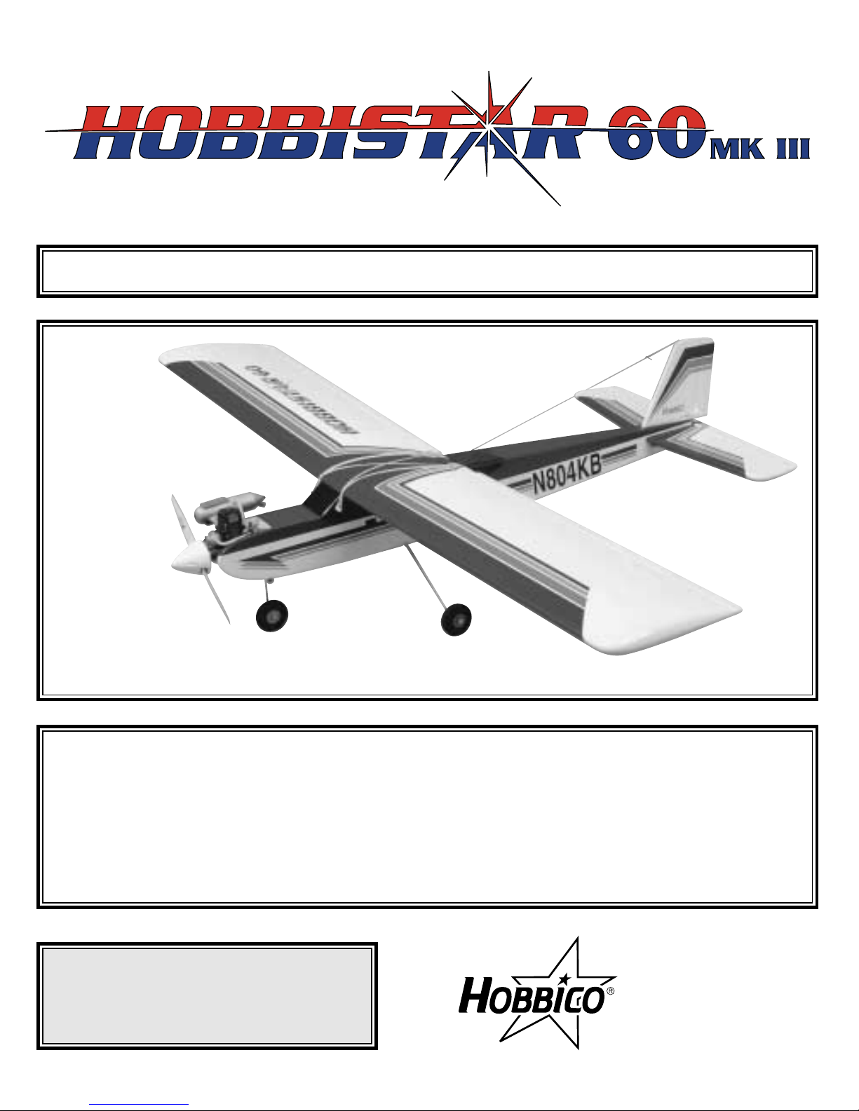
Congratulations and thank you for purchasing the
Hobbico Hobbistar .60 MKIII. You've made the right
decision by purchasing a “real” model airplane that
uses a .60-size engine and a 4-channel radio. Once
assembled and set up, there will be no fiddling with a
temperamental engine or constant troubleshooting to
figure out how to get the model to fly. Under the
guidance of a flight instructor, all you'll have to do is
concentrate on learning to fly. And after you've
mastered the Hobbistar, the engine and radio may be
installed in your next model!
IMPORTANT:
The best thing you can do to insure success is to
find a flight instructor who will inspect your
model for airworthiness and provide flying
lessons. It cannot be stated strongly enough that,
if you do not already know how to fly an R/C
airplane, you will probably not be able to fly this
model by yourself. It may appear to be easy, but
over-controlling and disorientation quickly
overcome inexperienced fliers swiftly ending their
first flight. If you haven't yet done so, contact the
local hobby shop and ask them to introduce you
to an instructor or an R/C club representative. If
there is no club or experienced R/C pilot nearby,
it would be worth even a long drive to find one-if
only for just a few flight lessons (then you'll have
an idea of what to expect).
If there is no hobby shop in your area, contact the
AMA (Academy of Model Aeronautics), the
governing body of model aeronautics. The AMA
can direct you to the closest R/C club whose
membership should have qualified flight
instructors. With the added benefit of insurance
coverage provided by the AMA, most clubs
require AMA membership to fly at their field.
Academy of Model Aeronautics
5151 East Memorial Drive
Muncie, IN 47302-9252
Tele. (800) 435-9262
Fax (765) 741-0057
Or via the Internet at: http://www.modelaircraft.org
IntroductionTable of Contents
3
1. Your Hobbistar .60 MKIII should not be
considered a toy, but rather a sophisticated, working
model that functions very much like a full-size
airplane. Because of its performance capabilities,
the Hobbistar .60 MKIII, if not assembled and
operated correctly, could possibly cause injury to
yourself or spectators and damage to property.
2. You must assemble the model according to the
instructions. Do not alter or modify the model, as
doing so may result in an unsafe or unflyable model.
In a few cases the instructions may differ slightly
from the photos. In those instances the written
instructions should be considered as correct.
3. You must take time to build straight, true and strong.
4. You must use an R/C radio system that is in firstclass condition, and a correctly sized engine and
components (fuel tank, wheels, etc.) throughout the
building process.
5. You must correctly install all R/C and other
components so that the model operates correctly on
the ground and in the air.
6. You must check the operation of the model before
every flight to insure that all equipment is operating
and that the model has remained structurally sound. Be
sure to check clevises or other connectors often and
replace them if they show any signs of wear or fatigue.
7. If you are not already an experienced R/C pilot,
you should fly the model only with the help of a
competent, experienced R/C pilot.
These are the items not supplied with the Hobbistar .60
MKIII that must be purchased separately. Where
appropriate, order numbers are provided in parentheses.
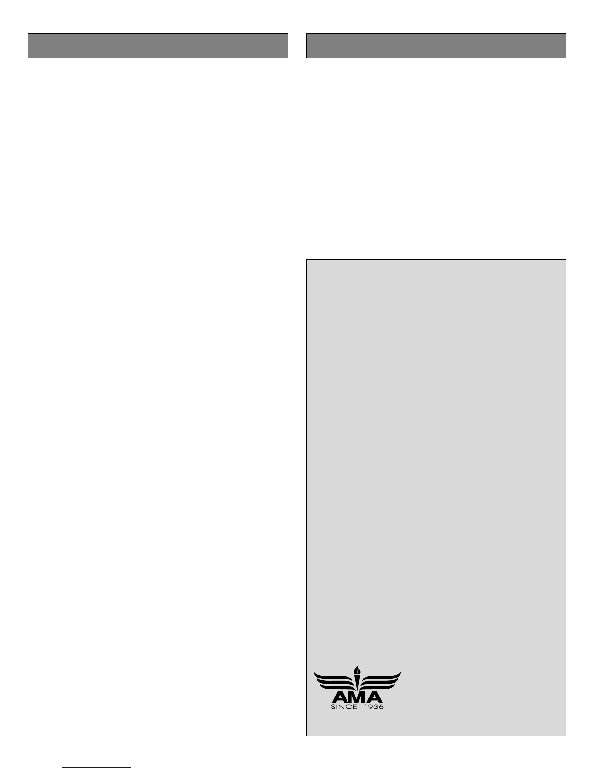
RADIO SYSTEM
A 4-channel radio control system with four servos is
required to fly the Hobbistar .60 MKIII. 4 “channels”
means that the radio is capable of operating four
controls. On a trainer model such as the Hobbistar
the controls are the ailerons, elevator, throttle and
rudder. Some 4-channel radio control systems
include only three servos, so a fourth servo may
have to be purchased separately.
ENGINE
A .60 to .65 cu in two-stroke model airplane engine
is required to fly the Hobbistar .60 MKIII. Basically,
there are two types of two-stroke engines; “ball
bearing” and “non ball bearing” engines. In addition
to having a crankshaft supported by two ball
bearings, most ball bearing engines have other
performance features that boost power and RPM
(and price). For the Hobbistar .60 MKIII, an
economical, non ball bearing engine is more than
suitable. Should you decide to go “all-out” and
Items Required
We, as the kit manufacturer, provide you with a
top quality kit and instructions, but ultimately the
quality and flyability of your finished model
depends on how you build it; therefore, we
cannot in any way guarantee the performance of
your completed model, and no representations
are expressed or implied as to the performance or
safety of your completed model.
Protect Your Model, Yourself & Others
Follow these Important
Safety Precautions
purchase a more powerful ball bearing engine
anyway, you’ll have to remember to throttle back to
slow the model while learning to fly. A suitable
propeller and spare propellers will also be required
(most two-stroke .60 engines run well with a 12 x 6
or 11 x 7 propeller, but refer to the recommendations
in the instructions that came with the engine).
TOOLS, BUILDING SUPPLIES AND ACCESSORIES
These are the rest of the items required to assemble
the Hobbistar .60 MKIII.
❏6" [150mm] servo extension (HCAM2701 for Futaba
®
)
❏ R/C foam rubber (1/4" [6mm] - HCAQ1000, or
1/2" [13mm] - HCAQ1050)
❏ Medium silicone fuel tubing (GPMQ4131)
❏ #64 rubber bands (1/4 lb [113g] box, HCAQ2020)
❏ Stick-on segmented lead weights (GPMQ4485)
❏Threadlocker thread locking cement (GPMR6060)
❏ 1/2 oz. [15g] Thin Pro
™
CA Glue (GPMR6001)
❏ 1/2 oz. [15g] Medium Pro CA+ Glue (GPMR6007)
❏ Pro 30-minute epoxy (GPMR6047)
❏ Denatured alcohol (for epoxy clean up)
❏ #1 Hobby knife (HCAR0105)
❏ #11 blades (5-pack, HCAR0211)
❏ #1 Phillips screwdriver (HCAR1022)
❏ #2 Phillips screwdriver (HCAR1024)
❏ Pliers
❏ Small metal file
❏ Masking tape
❏ 12mm (or appropriate size) prop wrench or
crescent wrench
❏ Drill and drill bits: 1/16" [1.6mm], 5/64" [2mm],
3/32" [2.4mm], #19 (or 11/64") [4.4mm]
OPTIONAL SUPPLIES AND TOOLS
These items are not absolutely required, but are
mentioned in the instructions and will help you
assemble the Hobbistar .60 MKIII
❏ Top Flite
®
MonoKote®sealing iron (TOPR2100)
❏ Top Flite Hot Sock iron cover (TOPR2175)
❏ 4 oz. [113g] aerosol CA activator (GPMR634)
❏ CA applicator tips (HCAR3780)
❏ CA debonder (GPMR6039)
❏ Epoxy brushes (6, GPMR8060)
❏ Mixing sticks (50, GPMR8055)
❏ Mixing cups (GPMR8056)
❏ Builder's Triangle Set (HCAR0480)
❏ Pliers with wire cutter (HCAR0630)
❏ Masking tape (TOPR8018)
❏ K & S #801 Kevlar thread (for stab alignment,
K+SR4575)
❏ Panel Line Pen (TOPQ2510)
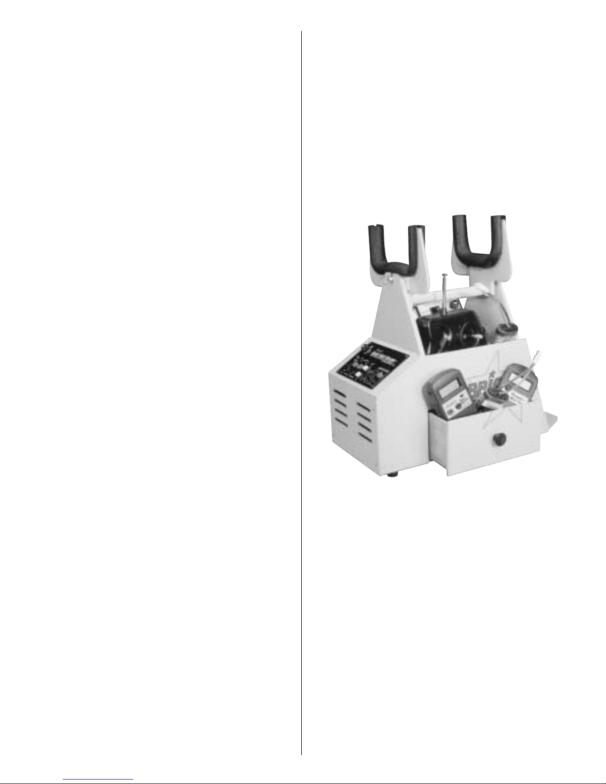
❏ CG Machine
™
(GPMR2400)
❏ Precision Magnetic Prop Balancer™ (TOPQ5700)
❏ Prop Reamer (GPMQ5005)
FIELD EQUIPMENT
When ready to fly, you'll need the equipment to fuel
the plane and start the engine. Perhaps you've already
made arrangements with the R/C club or your flight
instructor to borrow theirs, but eventually you'll want
to get your own. Refer to your hobby dealer for
specific recommendations on what to purchase.
Following is a list of the most important items…
❏ Model engine glow fuel (5%, 10% or 15%
nitromethane content is suitable)
❏ Hand-crank or electric fuel pump system with
fuel lines and fittings for transferring fuel from the
container into the fuel tank in the model.
❏ Glow plug igniter for starting the engine
❏ Battery for glow plug igniter (if not already
attached to igniter)
❏ Electric starter and 12v battery
❏ Field box for carrying starting equipment and tools
4

5
1
2
2
6
5
10
9
7
15
14
8
11
12
13
3
4
Kit Inspection
1. Fuselage
2. R&L wing halves w/ailerons
3. Stab w/elevator
4. Fin w/rudder
5. Main landing gear wires (2)
6. Nose gear wire
7. Fuel tank w/hardware
8. 1/4" x 1/2" x 10" [6 x 12 x 255mm]
balsa stick (fuel tank, receiver,
battery mounting) (2)
9. Cast aluminum engine mount
10. 2-3/4" [70mm] foam wheels (3)
11. 2-3/4" [70mm] white plastic
spinner w/4 spinner screws
12. 1/8" [3.2mm] plywood fuselage
servo tray
13. 1/8" [3.2mm] plywood wing
servo tray
14. 1/8" [3.2mm] plywood wing
joiners (3)
15. Hardwood wing dowels (2)
Before starting to build, take an inventory of all the parts to make sure the kit is complete and inspect the
parts to make sure they are of acceptable quality. If any parts are missing or are not of acceptable quality,
or if you need assistance with assembly, contact Product Support. When reporting defective or missing
parts, use the part names exactly as they are written in the Kit Contents list on this page.
Product Support:
Telephone: (217) 398-8970
Fax: (217) 398-7721
E-mail: airsupport@hobbico.com
Parts Photographed
(1) nylon nose steering arm
(1) nylon nose gear mount
(2) 2mm x 9-7/8" [250mm] threaded one-end
wire aileron pushrods
(1) 2mm x 27" [685mm] threaded one-end wire
throttle pushrod
(1) 2mm x 19-3/4" [500mm] wire nose wheel
steering pushrod
(2) nylon aileron torque rod horns
(2) nylon straps (main landing gear)
(5) nylon clevises
(5) nylon pushrod keepers
(2) nylon control horns w/mnt plates
(5) silicone retainers for clevises
(15) precut CA hinges
(4) 4 x 25mm Phillips-head screws (engine
mounting)
(6) 4 x 20mm Phillips-head screws (engine
mount, nose gear bearing)
(10) 4mm lock washer
(10) 4mm flat washer
(4) 4mm nut
(2) 2 x 16mm Phillips-head machine screws
(rudder control horn mnt)
(2) 2 x 20mm Phillips-head machine screws
(elevator control horn mnt)
(4) 3 x 12mm Phillips-head self-tapping screws
(main LG straps)
(4) 5mm wheel collars (main wheels)
(5) 4mm wheel collars (nose wheel)
(10) 3 x 5mm screw (for screw-lock connector,
wheel collars)
(1) 3 x 8mm screw (nose steering collar)
(2) 2mm washer (for pushrod connector)
(2) pushrod connector (screw-lock type)
(2) thumb nuts (for pushrod connectors)
(2) metal engine mount straps
(2) aileron torque rods (factory installed in wing)
(6) 4mm blind nuts (factory installed in firewall)
(1) 13-1/2" [340mm] plastic pushrod tube (throttle)
(1) 11-1/4" [285mm] plastic pushrod tube (for
nose wheel)
(2) 36" [915mm] threaded one-end pushrods
(elevator, rudder)
Parts Not Photographed

0" 1" 2" 3" 4" 5"
0 10 20 30 40 50 60 70 80 90 100 110 120 130
Inch Scale
Metric Scale
6
Ordering Replacement Parts
To order replacement parts for the Hobbico Hobbistar .60 MKIII ARF, use the order numbers in the
Replacement Parts List that follows. Replacement parts are available only as listed. Not all parts are
available separately (an aileron cannot be purchased separately, but is only available with the wing kit).
Replacement parts are not available from Product Support, but can be purchased from hobby shops or mail
order/Internet order firms. Hardware items (screws, nuts, bolts) are also available from these outlets. If you
need assistance locating a dealer to purchase parts, visit www.hobbico.com and click on “Where to Buy.”
If this kit is missing parts, contact Product Support.
Item
Description How to Purchase
Missing pieces Contact Product Support
Instruction manual Contact Product Support
Plans Construction Plans Not available
Hardware Individual hardware items Contact your hobby supplier
Parts listed below Contact your hobby supplier
HCAA3120 Fuselage Set (Fuselage, servo tray,wing dowels(2))
HCAA3121 Wing Set (Right & left wing panels w/ailerons, hinges (8), plywood wing
joiners (3), aileron servo tray)
HCAA3122 Tail Set (Fin & rudder, stab & elevator, hinges (7))
HCAA3123 Landing Gear Set (5mm main gear wires (2), 4mm nose gear wire, 5mm wheel
collars & screws (4), 4mm wheel collars & screws (2))
The Hobbistar .60 MKIII ARF is factory-covered with iron-on heat shrinkable model airplane covering.
Should repairs ever be required, the covering can be patched with Top Flite MonoKote or other similar
model airplane covering that has an iron-on adhesive on the back and shrinks with heat. Most coverings
are packaged in six-foot rolls, but some hobby shops sell covering by the foot. If only a small piece is
needed for a minor patch, perhaps a fellow modeler would give you some.
To convert inches to millimeters, multiply inches by 25.4
1/64" = .4mm
1/32" = .8mm
1/16" = 1.6mm
3/32" = 2.4mm
1/8" = 3.2mm
5/32" = 4mm
3/16" = 4.8mm
1/4" = 6.4mm
3/8" = 9.5mm
1/2" = 12.7mm
5/8" = 15.9mm
3/4" = 19mm
1" = 25.4mm
2" = 50.8mm
3" = 76.2mm
6" = 152.4mm
12" = 304.8mm
15" = 381mm
18" = 457.2mm
21" = 533.4mm
24" = 609.6mm
30" = 762mm
36" = 914.4mm
Metric Conversions
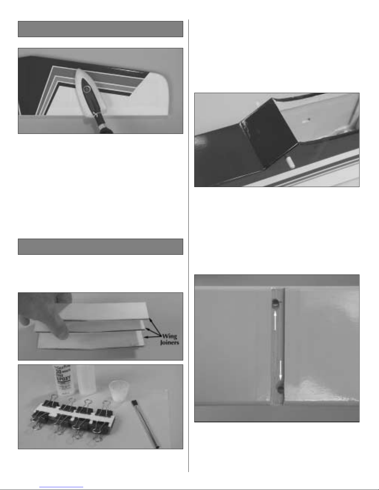
Examine the covering on the model. Occasionally,
the covering requires tightening to remove wrinkles
that develop. If necessary, use a model airplane
covering iron with a covering sock to tighten the
covering and remove wrinkles. Hint: Poke three or
four pin holes in the covering between the “ribs” in
the tail surfaces, allowing air to escape to fully
tighten the covering. Note: If you haven't yet
purchased a covering iron (or borrowed one from a
friend), this step may be done later.
There are a few steps that require 30-minute epoxy
that can be done first to speed assembly.
❏ 1. Use 30-minute epoxy to glue together the three
1/8" [3.2mm] plywood wing joiners. Be certain to
apply epoxy to all mating surfaces. (In other words,
apply epoxy to both sides of the joiner in the middle
and to the inside of both the joiner on the top and the
joiner on the bottom.) Hold the joiners together with
clamps. Wipe away excess epoxy before it hardens.
❏ 2. Round the ends of both 1/4" [6.5mm] wing
dowels. Cut the covering from the holes in the
fuselage for the dowels and glue them into position
with 30-minute epoxy. Lightly coat the dowels with
epoxy. (Only the front dowel is shown in the photo,
but there is a dowel at the aft end of the cutout in the
fuselage for the wing.)
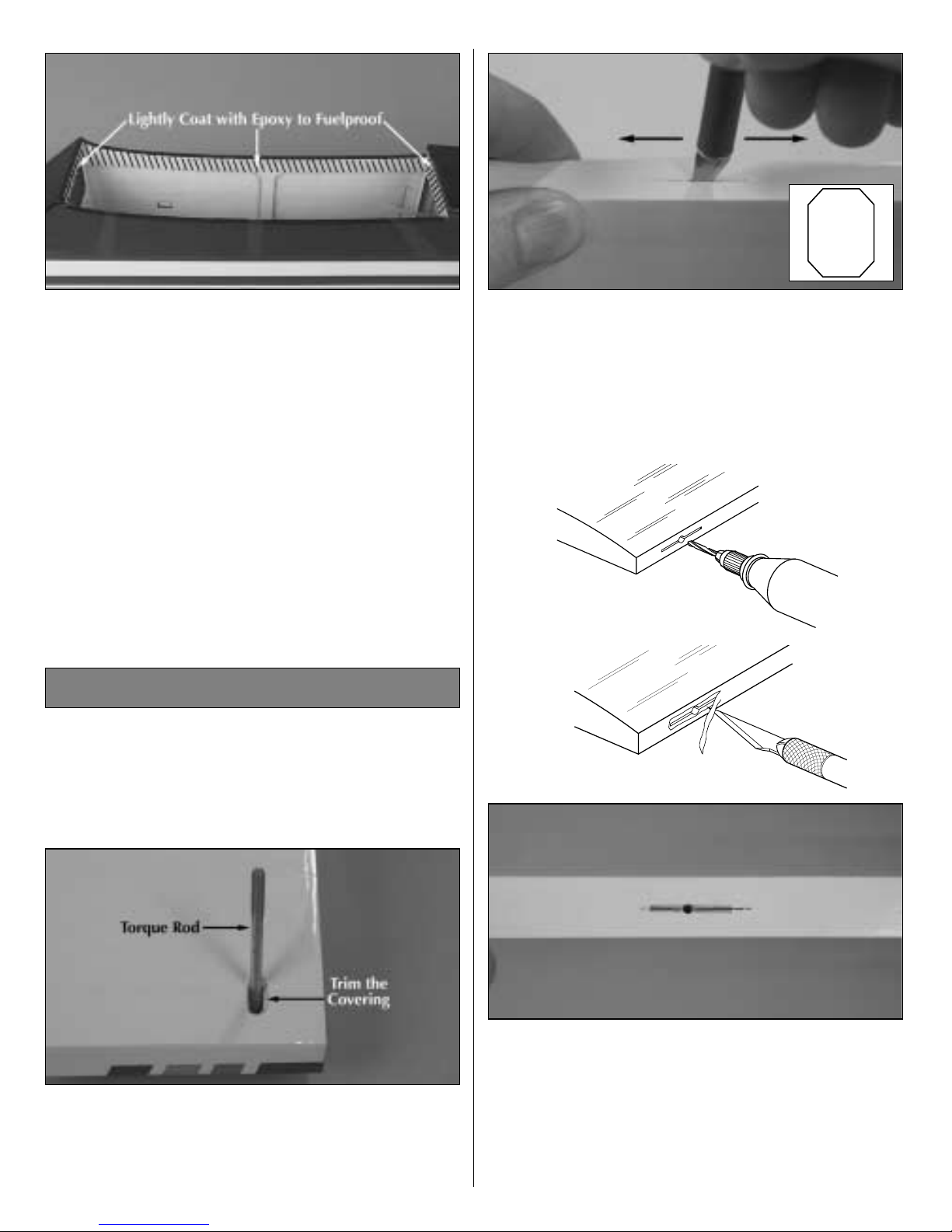
❏ 3. Use a hobby knife to bevel the inside edges of
the holes in the main landing gear rail where
indicated by the arrows to accommodate the bend
in the landing gear wire. Seal the exposed wood in
the landing gear rail with a light coat of epoxy.
Preparations
Tighten the Covering
7
❏ 4. Seal the edges of the covering around the
engine compartment with a thin coat of 30-minute
epoxy. Also use 30-minute epoxy to lightly coat the
inside of the fuselage all the way around the
opening for the wing (as indicated by the shaded
area). This will fuelproof the bare wood in case
engine exhaust residue seeps in.
JOIN THE AILERONS
Start with the right wing so yours matches the
photos the first time through.
❏❏1. Use a hobby knife with a #11 blade to neatly
trim the covering from the bottom of the right wing
around the aileron torque rod to allow full, unrestricted
movement of the rod.
❏❏2. Test fit the aileron to the wing with four CA
hinges but do not glue them in yet. If it is difficult to
join the aileron to the wing because the hinge slots
are too tight, remove the hinges. Widen the hinge
slots by inserting a #11 blade and moving it back
and forth a few times.
❏❏3. Remove the aileron from the wing. Drill a
3/32" [2.4mm] hole 1/2" [13mm] deep in the center
of the hinge slots to allow the thin CA used for gluing
in the hinges to fully “wick” all the way in. Cut a small
strip of covering from all the hinge slots in the wing
and aileron. For the best result, use a high-speed tool
such as a Dremel to drill the holes.
AWAY FROM THE SLOT
CUT THE COVERING
DRILL A 3/32" HOLE
1/2" DEEP, IN CENTER
OF HINGE SLOT
Assemble the Wing
8
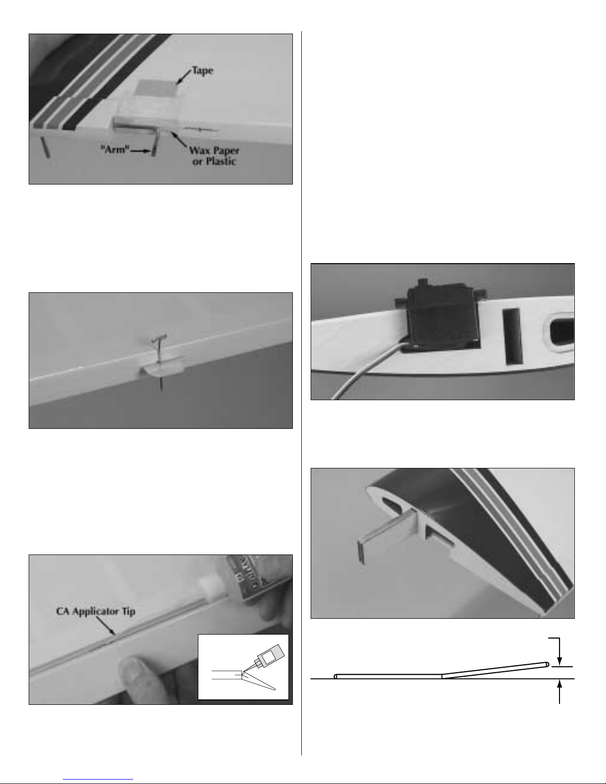
❏❏4. Tape a small piece of wax paper or a piece of
plastic from a sandwich bag to the wing under the
aileron torque rod. Coat the “arm” portion of the
torque rod and the hole and the slot in the aileron for
the torque rod with 30-minute epoxy. Immediately
proceed to the next step.
❏❏5. Join the aileron to the torque rod and wing
with the hinges. If the hinges don't remain centered,
stick a pin through the hinge to hold it in position.
Be certain there is a small gap between the aileron
and the wing—just enough to slip a piece of paper
through or to see light through. Remove any pins
that were used to center the hinges.
❏❏6. Apply six drops of thin CA to both sides of all
the hinges. Allow a few seconds between drops so
the CA fully soaks into the hinge rather than being
drawn into the hinge gap thus gluing the aileron to
the wing. Note the CA applicator tip (HCAR3780)
on the CA bottle to control and pinpoint the CA that
comes out.
❏❏7. Stack a few paper towels over each other and
cut them into approximately 2" [50mm] squares.
Moisten one of the squares with denatured alcohol
and use it to wipe away excess epoxy that came out
of the aileron.
❏ 8. Return to step 1 and join the left aileron to the
left wing panel the same way.
JOIN THE WING
❏ 1. Test fit the aileron servo in both wing halves to
make sure the servo fits. If necessary, enlarge the cut
outs in the wing to accommodate the servo.
❏ 2. Test fit the wing joiner you glued together earlier
into both wing halves, then test fit the wing halves
with the joiner. There should be no gap in the wing.
2-3/8" (± 3/8")
9
T
H
IN
C
A
 Loading...