

Page 1
INSTRUCTION MANUAL
FLWA4140 - Edge 540 RB 1,2 m
EDGE 540 RB
Fully licensed through
Red Bull GmbH
Austria
78239
Version 1.00
Technical data : Edge 540 RB
Wingspan 1 290 mm
Lenght 1 150 mm
Take o weight 1 250 g
Wing Area 28 dm²
Wing loading 44,6 g/dm²
Battery LiPo 3S 2200 mAh
RC Functions Ailerons, elevator,
rudder, motor
Please read the instruction manual carefully and take notice of the safety guidelines.
If the model is given to a third party, always include this instruction manual to the model.
The Flitework Gmbh assumes no liability in case of misprints. Technical amendments reserved.
Distributed by :
Designed in Austria - Made in China
www.hobbico.de
Page 2
TABLE OF CONTENTS
Introduction ........................................................................................ 2
General informations ...................................................................... 2
Environment protection infos ....................................................2
Safety Precautions ...........................................................................3
Additional items required ............................................................3
RecomMended accessories ..........................................................3
Kit check ................................................................................................ 4
Spare parts ........................................................................................... 4
Contenu du kit .................................................................................... 5
Installing the elevator ....................................................................6
Elevator linkage ................................................................................. 7
Mounting the rudder ......................................................................8
Rudder linkage ...................................................................................9
Installing the landing gear ........................................................ 10
Installing the motor ...................................................................... 11
Mounting the main wings .......................................................... 12
ENGLISH
Introduction
Installing the RC components .................................................. 12
Installing the battery ................................................................... 13
Final ight preparation ............................................................... 13
Center of gravity (C.G.) .............................................................13
Balance the Model Laterally .................................................. 13
Check the Control Directions ................................................ 13
Set the Control Throws ............................................................ 14
Check-List .......................................................................................... 14
Hobbico Service Line Europe ................................................... 14
Hobbico Service Line USA .......................................................... 14
Flitework Service Line..................................................................14
The Flitework Edge 540 1.2m is a handy sized model, which is constructed for a big range of aerobatic- or 3D ight.
In case of the light weight construction the ight characteristics are very good-natured. This Edge is a nice designed
trainer for every day.
The original plane is located in Hangar 7 of Red Bull - Salzburg/Austria. Red Bull uses it for air shows, own by the
multiple champion of the Red Bull Airrace - Hannes Arch.
Attention please!
Remote controlled model planes are not a toy! For assembling, ying and servicing such models, you need a high
grade of technical comprehension and liability. Careless assembling and operation may cause personal and material
damage.
Because the Flitework GmbH has no inuence on assembly, RC installation, operation and servicing of the ight
device, any liability is rejected under explicit advice to these dangers.
GENERAL INFORMATIONS
• Read this manual and its safety precautions carefully! Keep this manual
and if you give the model to a third party, put this manual to the model.
• Take care, that you are familiar with your transmitter and all electronic
• The symbols on the package show you, that the model and its accessories
should not be put to waste. All electric and electronic parts should be deposed
to places of waste management.
ENVIRONMENT PROTECTION INFOS
components, used in your plane.
• Take care of all safety instructions of tools, which are you using to
assemble this model.
• Only take glues, which are recommended for the specic materials and
which are approved for model business.
• Batteries and accumulators must be removed from
the devices and should be deposed to the correct
waste management organisation. Take information
from your home town government.
• Before assembling please check all parts of this kit. If some parts are
missing or have a mistake, please call.
2
Page 3

SAFETY PRECAUTIONS
❍ 1. Your Edge 540 1.2m should not be considered a toy, but
rather a sophisticated, working model that functions very
much like a full-size airplane. Because of its performance
capabilities, the Edge 540, if not assembled and operated
correctly, could possibly cause injury to yourself or
spectators and damage to property.
❍ 2. You must assemble the model according to the
instructions. Do not alter or modify the model, as doing
so may result in a unsafe or unyable model. In a few
cases the instructions may dier slightly from the photos.
In those instances the written instructions should be
considered as correct.
❍ 3. You must take time to build straight, true and strong.
❍ 4. You must use an R/C radio system that is in rst-class
condition.
❍ 5. You must correctly install all R/C and other components
so that the model operates correctly on the ground and
in the air.
❍ 6. You must check the operation of the model before
every ight to insure that all equipment is operating and
that the model has remained structurally sound. Be sure
to check clevises or other connectors often and replace
them if they show any signs of wear or fatigue.
❍ 7. If you are not already an experienced R/C pilot, you
should y the model only with the help of a competent,
experienced R/C pilot.
❍ 8. While this kit has been ight tested to exceed normal
use, if the plane will be used for extremly high stress
ying, such as racing, or if an engine larger than one
in the recommended range is used, the modeler is
responsible for taking steps to reinforce the high stress
points and/or substituting hardware more suitable for the
increased stress.
ADDITIONAL ITEMS REQUIRED
❍ 1 x Motorset FW 3545/100 (Référence : FLWA8003)
❍ 3 x Servos TSX10 (Réf. : TACM0210) (Elevator/Ailerons)
❍ 1 x Servo TSX20 (Réf. : TACM0220) (Rudder)
❍ 1 x LiPo 3S 2200 - 2 500 mAh 25C (Order No: GPMP0861
or FPWP2253)
❍ 1 x Receiver min 4 channels (Tactic TR624 Order No.
TACL0624 or Tactic TR625Order No : TACL0625)
❍ 2 x 300 mm servo extensions (HCAQ7332)
❍ 2 x 100 mm servo extensions (HCAQ7330)
RECOMMENDED ACCESSORIES
❍ Hobby knife
❍ Flat screw driver
❍ Philips screw driver
❍ 5 min. Epoxy glue
❍ CA glue thin
❍ Set of driller
❍ Thread lock - blue
❍ Long nose pliers
❍ Mini grinder
ENGLISH
Flitework quality
We, as the kit manufacturer, provide you with a top quality kit
and instructions, but ultimately the quality and yability of
your nished model depends on how you build it; therefore,
we cannot in any way guarantee the performance of your
completed model and no representations are expressed or
implied as to the performance or safety of your completed
model.
3
3
Page 4

KIT CHECK
Before starting to build, use the Kit Contents list to take an
inventory of this kit to make sure it is complete and inspect
the parts to make sure they are of acceptable quality. If any
parts are missing or are not of acceptable quality, or if you
need assistance with assembly, contact Hobbico Product
Support.
Service center Revell GmbH
Henschelstr. 20-30, 32257 Bünde,
Germany
Tel: +49 52239 65144
Email: service@hobbico.de
Hobbico Product Support
3002 N. Apollo Drive Suite 1
Champaign IL 61822 USA
Telephone: (217) 398-8970 ext. 6
Fax: (217) 398-7721
ENGLISH
E-mail: airsupport@hobbico.com
SPARE PARTS
Spare parts can be purchased from hobby shops or mail order/
Internet order rms. Hardware items (screws, nuts, bolts)
are also available from these outlets. If you need assistance
locating a dealer to purchase parts, contact Product Support.
NOTES
Service-Abteilung Revell GmbH
Henschelstr. 20-30, 32257 Bünde, Germany
Tel: 01805 110111 (nur für Deutschland)
(Anrufkosten: 14 Cent/Min. a. d. dt. Festnetz;
Mobilfunk max. 42 Cent/Min.)
Email: Hobbico-Service@Revell.de
Order N° Part name
FLWA4141 Edge 540 RB 1.2m Fuselage
FLWA4142 Edge 540 RB 1.2m Elevator complete
FLWA4143 Edge 540 RB 1.2m Main wing set
FLWA4144 Edge 540 RB 1.2m Carbon wing joiner
FLWA4145 Edge 540 RB 1.2m Motor cowl
FLWA4146 Edge 540 RB 1.2m Canopy
FLWA4147
FLWA4148 Edge 540 RB 1.2m Wheel pants
FLWA4149 Edge 540 RB 1.2m Rudder
FLWA4996 Edge 540 RB 1.2m Tail gear complete
FLWA4997 Edge 540 RB 1.2m Main wheels
FLWA4998 Edge 540 RB 1.2m Linkage set
FLWA4999 Edge 540 RB 1.2m Screw set
Edge 540 RB 1.2m Landing gear bow
including axles and screws.
4
Page 5
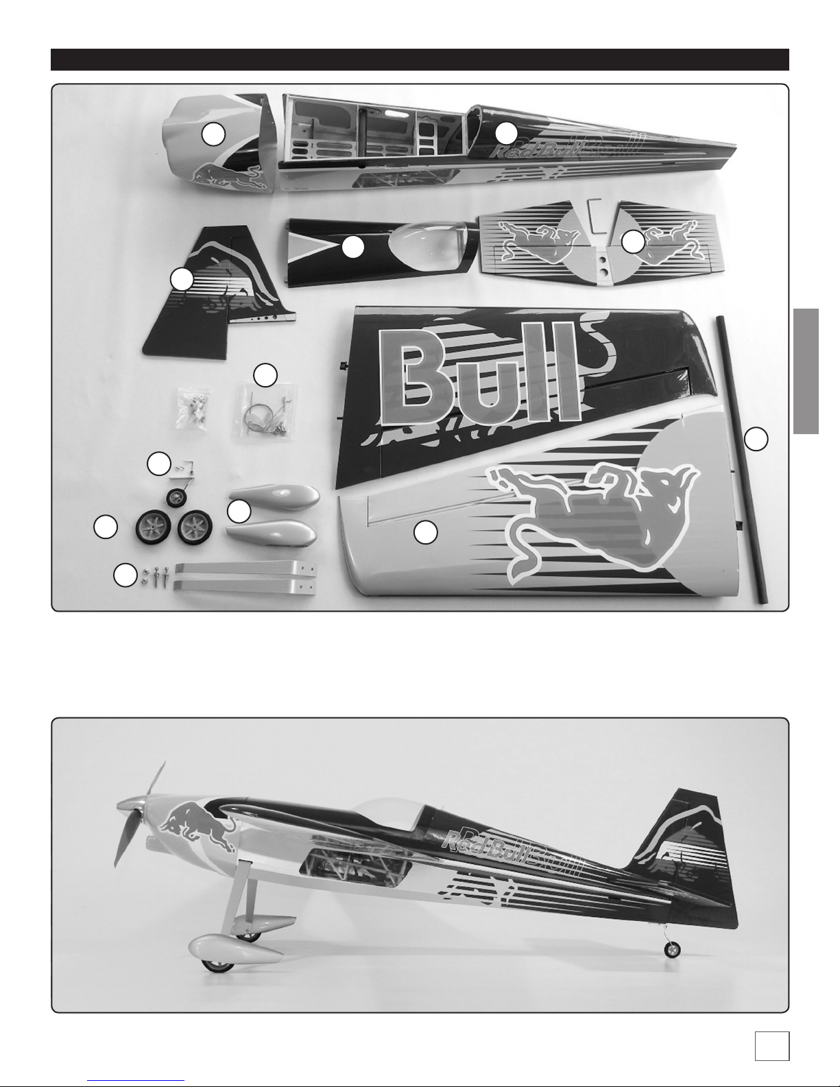
CONTENU DU KIT
12
11
1
3
5
10
9
6
2
4
ENGLISH
7
8
1 Painted motor cowl
2 Fuselage
3 Canopy
4 Elevator complete with connection
bracket
5 Rudder
6 Wing set
7 Carbon ber wing joiner 460x13mm
8 Landing gear bows with axles
9 Wheel pants
10 Linkage- and screw set
11 Tail landing gear
12 Main wheels
5
Page 6

INSTALLING THE ELEVATOR
❏ 1. Put the eece hinges into the slots of the elevator aps.
Mark the middle of the hinges with a permanent marker. Drill
1.5mm holes into the marked spots of the aps. These holes
are adhesion channels for the thin liquid CA glue. With this
system, you get a bigger bonding area than without the hole.
ENGLISH
It is very important, that the hinges are well glued..
❏ 2. Repeat the same procedure for the elevator.
❏ 4. Check the correct placement, measuring the distance
from elevator to a center point of the fuselage on both sides.
Now mark the fuselages shape on the elevator on both sides.
❏ 5. Take out the elevator and remove the covering lm
between the lines. Use a sharp hobby knife to cut the lm. Be
careful, that you do not cut into the wood of the elevator.
❏ 6. Put the elevator again into the fuselage and check the
correct alignment.
❏ 3. Put the elevator into the fuselage and look for a correct
alignment according to the center line of the fuselage.
6
❏ 7. Use thin CA glue with a needle applicator, to glue the
elevator into the fuselage. Be careful, that no CA glue is
dropping on the lm. You never can remove CA spots from
the covering lm.
Page 7

❏ 10. Remove oozing epoxy glue with cotton buds and look,
that the ap gaps are free of glue.
❏ 11. Is the epoxy glue hardened and are the aps are
movable smoothly, you can glue the eece hinges with thin
CAglue. Take the needle of a syringe for application. Start the
application from the middle of the hinges, where the 1,5mm
hole has been drilled. After the CA-glue is dry, move the aps
sometimes back and forth to get them smoothly movable.
ELEVATOR LINKAGE
ENGLISH
❏ 8. Draw the outer side of the elevator plus 1mm gap on
both sides to a paper sheet. Take the elevator aps and the
steel bracket, put it together and compare the distances with
your drawing. If necessary, rework the drill holes so, that the
aps are matching to the drawing. Both aps should be at
on the table .
Do not glue the brackets to the aps at this moment.
❏ 9. Sand the connection bracket on the gluing areas for
better adhesion of the epoxy glue. Put the bracket into the
fuselage. Fix the eece hinges with pins in the aps. Put eposxy
glue into the 2mm holes of the aps and into the groove of the
ap. Also put a little bit epoxy glue on both sides of the steel
bracket. Put aps and elevator together and x with tape. Take
care, that both aps are in plane and not distorted. Distorted
elevator aps are like ailerons.
❏ 1. Sand the elevator lever on both sides on the adhesive
area. Remove the lm over the slot for the lever. Put tapes
around the slot to avoid ugly glue spots on the lm and glue
the lever into the slot.
7
Page 8

❏ 2. Put a servo extension cable (300-350mm) to the
elevatorservo and x the connectors with shrinking tube or
adhesive tape.
ENGLISH
MOUNTING THE RUDDER
❏ 1. 18mm from the bottom of the rudder, drill a 2mm hole
for the tail gear. Make a small groove from the hole to the
bottom of the rudder.
❏ 3. Remove the lm on the left side of the fuselage from the
servoframe. Place the servo and drill 1,5mm holes for screws.
Screw the servo on the fuselage.
❏ 4. Mount the pushrod carrier into the ap lever. Use blue
locking agent for all screws and look for good movement of
the carrier. Hook the rod into the servolever and put it through
the hole of the carrier. Bring servolever and ap into neutral
position and x the clamp screw of the carrier. Always take
care of smoothly mobility of the ap!
❏ 2. Remove the lm from the border of the groove to have
area for gluing.
❏ 3. Now assemble the tailgear like in the picture below.
8
Page 9

❏ 4. Roughen the steel wire on the adhesive surface and glue
it with epoxy glue into the rudder. The wheel axis should be
rectangular to the rudder ap. The pivot point of the rudder
should match with the pivot point of the tail gear.
RUDDER LINKAGE
❏ 1. Thread the steering wires into the fuselage, using a
plastic bowden cable. The wires should be crossed inside the
fuselage.
ENGLISH
❏ 2. Thread the wire rst trough the clamp sleeve and then
trough the rudder lever, than back to the sleeve. Crimp the
sleeve with plieres and bend the outstanding end backwards.
❏ 5. Now you can glue the ber glass lever symmetric into
the slot of the rudder.
❏ 6. Insert the eece hinges into the rudder and x them
with pins. Now put the rudder into the fuselage and glue the
eece hinges like you did with the elevator.
❏ 7. Drill 1,5mm holes through the holes of the aluminium
tail gear holder. Screw the tailgear with 2.3x11mm wood
screws onto the fuselage.
❏ 8. Put the tail wheel on the axis and x it with the aluminium
adjusting collar. Use locking agent for the set screw.
❏ 3. Fit the rudder servo with rubber bushings and metal
sleeves. Put the rudder servo to its place and drill 1.5mm holes
for the screws. Fix the servos with the provided screws.
❏ 4. Screw the linkage
carriers to the servo lever.
Use blue thread lock and
take care, that the carriers
keep mobile. Adjust the
rudder servo to neutral
position and mount the
servo lever.
9
Page 10

❏ 5. Thread the steering wire into the eye bolts and the clamp
sleeves. Adjust the wire so, that the eye bolt can easy reach
the linkage carrier of the servo lever. Then crimp the sleeves,
shorten the wires and bend the end. Put the eye bolts through
ENGLISH
the linkage carriers until the wires have a light tension and x
them with the set screw.
INSTALLING THE LANDING GEAR
❏ 2. Screw the wheel together with the pants onto the
aluminium landing gear bow.
❏ 3. Put the gear bows into the slots of the fuselage and x
them, using 2pcs of M3x8mm screws on both sides. Don’t
forget locking agent.
❏ 1. Install the axle and use distance shims, to center the
wheels in the wheel pants. Fix the wheel on the axle, using the
aluminium adjusting collar. (Thread lock!!)
10
❏ 4. Adjust the wheel pants according to the fuselage, drill
a 1,5mm hole through the hole in the gear bow and x the
pants with the provided wood screws.
Page 11

INSTALLING THE MOTOR
❏ 1. Screw the prop adapter and the aluminium cross to the
motor. Use blue thread lock.
❏ 4. Bring the motor cowl in the correct position. Check the
position with the spinner base plate. There should be a gap of
2mm between the cowling and the spinner. Fix the cowl with
tapes in this position.
ENGLISH
❏ 2. Screw the motor with 4 pcs of M4x20 screws and the
12mm distance rolls against the rewall frame. Also use thread
lock for this connection. The motor cables should be place on
left side.
❏ 3. The ESC can be xed inside on the left side of the
fuselage, using a doublesided adhesive tape or a cable tie..
❏ 5. The cowling should overhang the rewall frame for
about 10mm. Then the position is OK.
❏ 6. Drill on both sides 1,5mm holes through the cowling
and through the wood of the fuselage. You can sti out the
hole in the wood, using thin CA-glue. Then you can mount
the cowling with 4 pcs of 2.3x8 wood screws. Do not install
the propeller and the spinner, until all radio adjustments are
nished. So the propeller cannot make any damage or hurts, if
somethging goes wrong during RC adjustment.
11
Page 12

❏ 7. On the bottom side of the fuselage you can cut out the
opening for cooling air stream.
MOUNTING THE MAIN WINGS
❏ 1. Glue the ailerons into the wings, like you did with
elevator or rudder aps.
ENGLISH
❏ 2. Remove the covering lm from the servo- and ap slots.
Glue the aileron ap levers with epoxy glue into the slots.
Sand the adhesive areas of the levers before.
❏ 4. Hook the Z-cranked end of the linkage into the servo
horn. Insert the other end into the hole of the linkage carrier.
Set the servo and the aileron ap into neutral position. Fix the
clamp screw of the carrier. Don’t forget locking agent.
❏ 5. Repeat the procedure for the second main wing.
INSTALLING THE RC COMPONENTS
For operation you need at least a four channel receiver. We
recommend the Tactic TR624 (TACL0624). Additional you
need 2 pcs of 100mm Servo extension cables for connecting
the aileron servos (HCAQ7330).
If you dismount the wings for transport, you can disconnect
the aileron servos easily.
If you reinstall the wings for ight, take care, that the aileron
servos are connected to the correct channels!!
❏ 3. Put the servos into the servo slots. The servo lever should
point to the exterior end of the wing. Drill 1,5mm holes and
screw the servos into the wing. Use the screws, provided with
the servos. Install the linkage carrier like you can see in the
picture above. The clamp screw shall point to the fuselage.
Use blue locking agent for the nut of the carrier. Take care of
a good mobility of axis of the carrier. Otherwise the linkage
becomes sti.
12
In the picture you can see a possible arrangement of the
RC-components.
The receiver is xed with a double sided adhesive tape to the
left side of the fuselage. The cables were folded, if to long and
bundled with cable ties. The plugs for left and right aileron
servo are marked with a paint stick.
Very important is, that the antenna of the Rx is free and not
surrounded with cable jam. Also avoid the silver colored parts
of the lm. This lm includes aluminium particles, which are
shielding the 2.4GHz signal a little.
Page 13

FULL
THROTTLE
RUDDER
GOES
RIGHT
ELEVATOR
GOES DOWN
LEFT AILERON
GOES DOWN
RIGHT AILERON
GOES UP
4 CHANNELS SETUP
(STANDARD MODE 1)
FULL
THROTTLE
RUDDER
GOES
RIGHT
ELEVATOR
GOES DOWN
LEFT AILERON
GOES DOWN
RIGHT AILERON
GOES UP
4 CHANNELS SETUP
(STANDARD MODE 2)
INSTALLING THE BATTERY
As underlay of the battery, a anti-slip mat of the DIY-store is
very useful. You can x this mat with a double-sided adhesive
tape to the battery-place.
For xing the battery, we recommend the Flitework battery
belt with 200mm.
The 2200mAh battery in correct position.
CHECK THE CONTROL DIRECTIONS
❍ 1. Turn on the transmitter and receiver and center the
trims. If necessary, remove the servo arms from the servos
and reposition them so they are centered. Reinstall the
screws that hold on the servo arms.
❍ 2. With the transmitter and receiver still on, check all the
control surfaces to see if they are centered. If necessary,
adjust the clevises on the pushrods to center the control
surfaces.
ENGLISH
FINAL FLIGHT PREPARATION
CENTER OF GRAVITY C.G.
More than any other factor, the C.G. (center of gravity/
balance point) can have the greatest e ect on how a model
ies and could determine whether or not your rst ight will
be successful. If you value your model and wish to enjoy it
for many ights, DO NOT OVERLOOK THIS IMPORTANT
PROCEDURE. A model that is not properly balanced may be
unstable and possibly un yable.
The CG-point is 70-80mm back from the leading edge of
the main wing, measured close to the fuselage. The middle
of the wing joiner are at 80mm. Mark the CG with a permanent
marker or with small adhesive dots.
The nose of the plane should point downward a little, if you
hold the model at the CG points. Move the battery until the
CG is correct.
❍ 1. With the wing level, have an assistant help you lift the
BALANCE THE MODEL LATERALLY
model by the engine propeller shaft and the bottom of
the fuse under the TE of the n. Do this several times.
❍ 2. If one wing always drops when you lift the model, it
means that side is heavy. Balance the airplane by adding
weight to the other wing tip. An airplane that has been
laterally balanced will track better in loops and other
maneuvers.
❍ 3.The right drive direction of the motor should be tested
without mounted propeller.
Do not test the power drive with mounted propeller in
your workshop!!
13
Page 14

ENGLISH
Elevator
Rudder
Ailerons
SET THE CONTROL THROWS
These are the recommended
control surface throws :
3D rate Normal aerobatics
Up
Maximum
Right
Maximum
MaximumUpMaximum
Down
Maximum
Left
Maximum
Down
20 mmUp20 mm
Right
40 mm
30 mmUp30 mm
Down
Left
40 mm
Down
❍ 6. Make sure all hinges are securely glued in place.
❍ 7. Reinforce holes for wood screws with thin CA where
appropriate (servo mounting screws, cowl mounting
screws, etc.).
❍ 8. Conrm that all controls operate in the correct direction
and the throws are set up according to the manual.
❍ 9. Make sure there are silicone retainers on all the clevises
and that all servo arms are secured to the servos with the
screws included with your radio.
❍ 10. Secure connections between servo wires and Y
connectors or servo extensions and the connection
between your battery pack and the on/o switch with
vinyl tape, heat shrink tubing or special clips suitable for
that purpose.
❍ 11. Make sure any servo extension cords you may have
used do not interfere with other systems (servo arms,
push rods, etc.).
❍ 12. Balance your propeller (and spare propellers).
❍ 13. Tighten the propeller nut and spinner.
❍ 14. Place your name, address, AMA number and
telephone number on or inside your model.
❍ 15. Inspect all cables from ight to ight!
❍ 16. If you wish to photograph your model, do so before
your rst ight.
❍ 17. Range check your radio when you get to the ying
eld.
CHECKLIST
During the last few moments of preparation your mind
may be elsewhere anticipating the excitement of the
rst ight. Because of this, you may be more likely to
overlook certain checks and procedures that should be
performed before the model is own. To help avoid this,
a checklist is provided to make sure these important
areas are no overlooked. Many are covered in the
instruction manual, so where appropriate, refer to the
manual for complete instructions. Be sure to check the
items o as they are completed (that's why it's called a
check list!).
❍ 1. Check the C.G. according to the measurements
provided in the manual.
❍ 2. Be certain the battery and receiver are securely
mounted in the fuse. Simply stung them into place with
foam rubber is not sucient.
❍ 3. Look for a correct position of your receiver antenna or
antennas. The antenna should not be close to other wires
inside the fuselage.
❍ 4. Balance your model also laterally.
❍ 5. Use threadlocking compound to secure critical
fasteners such as the set screws that hold the wheel
axles to the struts, screws that hold the carburetor arm (if
applicable), screw-lock push rod connectors, etc.
Have a ball! But always stay in control and y
in a safe manner.
GOOD LUCK AND GREAT FLYING!
HOBBICO SERVICE LINE EUROPE
Service department Revell GmbH
Henschelstr. 20-30, 32257 Bünde, Germany
Tel: +49 52239 65144
Email: service@hobbico.de
HOBBICO SERVICE LINE USA
Hobbico Product Support
3002 N. Apollo Drive Suite 1
Champaign IL 61822 USA
Telephone: (217) 398-8970 ext. 6
Fax: (217) 398-7721
E-mail: airsupport@hobbico.com
FLITEWORK SERVICE LINE
Service department Flitework GmbH
Geymannstr. 27, 4713 Gallspach, Austria
Tel: +43 664 3231 059
Email: technik@itework.at
14
Page 15

NOTES
ENGLISH
15
Page 16

ENGLISH
Flitework GmbH
Geymannstraße 27
4713 Gallspach
Austria / Europe
16
Tel: +43 664 3231059
Skype: itework
Mail.: oce@itework.at
www.itework.at
 Loading...