

Page 1
Fully licensed through the
Red Bull GmbH - Austria
INSTRUCTION MANUAL
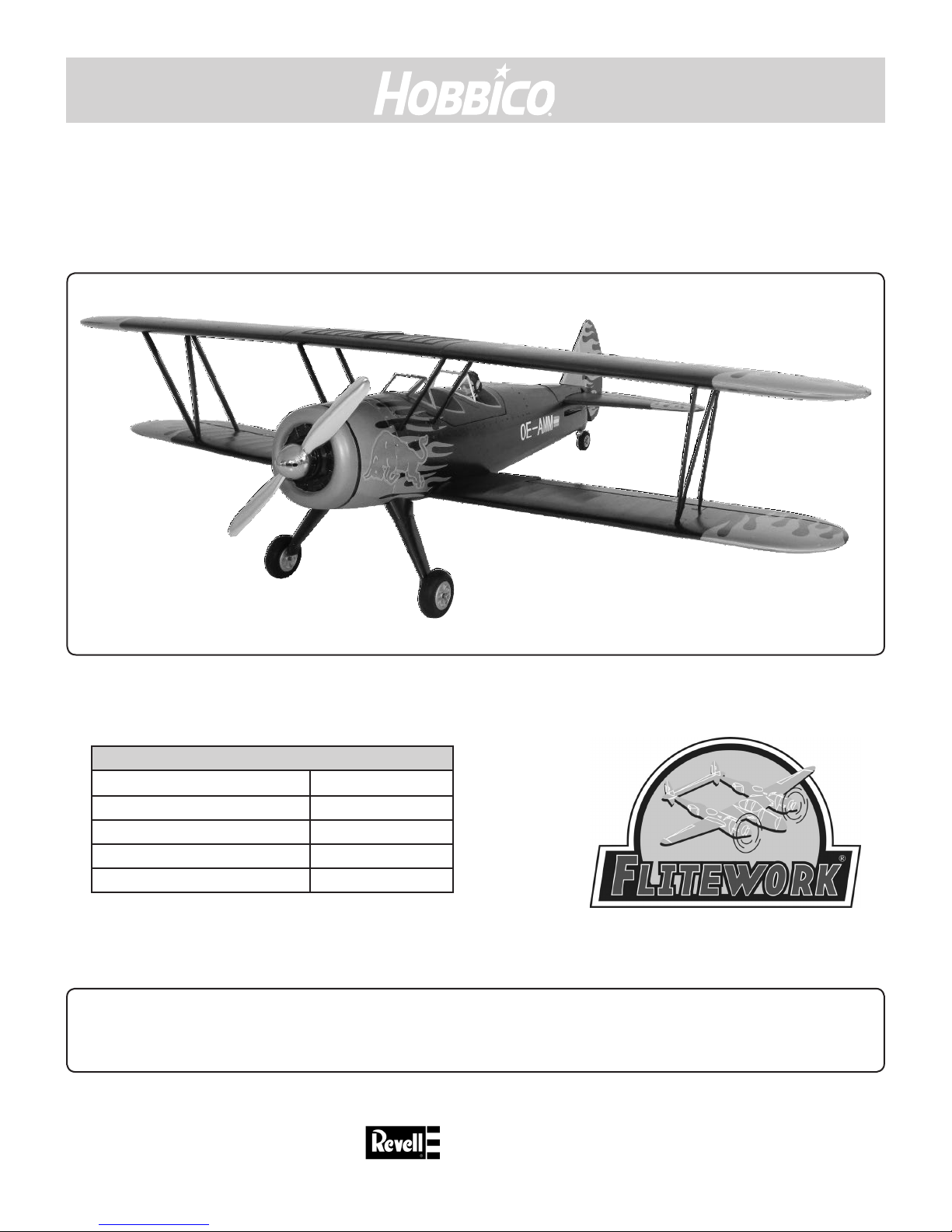
FLWA4110 - PT17-XS
78101
Technical data :PT17-XS
Wingspan 1200 mm
Length 970 mm
Take o weight 1600 g
Battery 4S 2500 mAh
RC Functions 4 channels
Please read the instruction manual carefully and take notice of the safety guidelines.
If the model is given to a third party, always include this instruction manual to the model.
The Flitework Gmbh assumes no liability in case of misprints. Technical amendments reserved.
Version 1.00
Distributed by
www.hobbico.de
Page 2
TABLE OF CONTENTS
General informations ..........................................................2
Environment protection infos ........................................2
Introduction ............................................................................2
Safety precautions ...............................................................3
Additional items required ................................................4
Hardware and accessories .............................................4
Useful tools .........................................................................4
Spare parts for the PT17-XS .............................................4
Kit check ....................................................................................4
Content of delivery .............................................................5
Part List .................................................................................5
Installing the main gear .....................................................5
Adding the wind shields ....................................................6
Installing the tail unit .........................................................6
Mounting the main wings .................................................6
Mounting the upper wing .................................................7
Receiver installation ............................................................8
ENGLISH
Before ight .............................................................................8
Get the model ready to y ................................................8
Check the Control Directions .......................................8
Set the Control Throws ...................................................9
Preight .....................................................................................9
Identify your model .........................................................9
Charge the Batteries ........................................................9
Balance Propellers ............................................................9
Ground check .....................................................................9
Range check .......................................................................9
Engine safety precautions ............................................. 10
Check-List ..............................................................................10
GENERAL INFORMATIONS
• Read this manual and its safety precautions carefully! Keep this manual and if
you give the model to a third party, put this manual to the model.
• Take care, that you are familiar with your transmitter and all electronic
components, used in your plane.
• Take care of all safety instructions of tools, which are you using to assemble
this model.
• Only take glues, which are recommended for the specic materials and which
are approved for model business.
• Before assembling please check all parts of this kit. If some parts are missing or
have a mistake, please call our service center.
Introduction
• The symbols on the package show you, that the model
and its accessories should not be put to waste. All electric
and electronic parts should be deposed to places of
waste management.
• Batteries and accumulators must
be removed from the devices and
should be deposed to the correct
waste management organisation. Take
information from your home town
government.
ENVIRONMENT PROTECTION INFOS
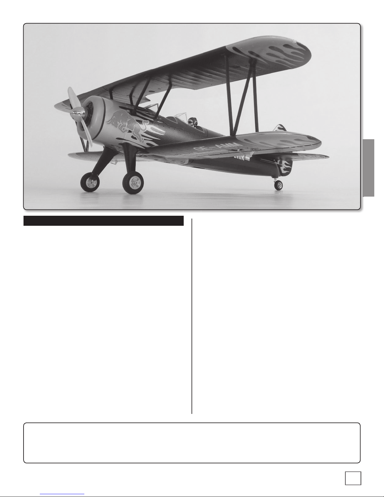
This biplane was developed 1934 as a trainer for the US. Army. Until this area the PT-17 fascinates a lot of peoples on
a lot of air shows with its unique sound and nice ight shilouette. Same as the original one, is the Flitework PT-17 an
exciting model with a lot of lovely details and its scale look.
Attention please!
Remote controlled model planes are not a toy! For assembling, ying and servicing such models, you need a high
grade of technical comprehension and liability.
Careless assembling and operation may cause personal and material damage.
Because the Flitework GmbH has no inuence on assembly, RC installation, operation and servicing of the ight
device, any liability is rejected under explicit advice to these dangers.
2
Page 3
ENGLISH
SAFETY PRECAUTIONS
1. Your PT17-XS should not be considered a toy, but rather a
sophisticated, working model that functions very much like
a full-size airplane. Because of its performance capabilities,
the PT17-XS if not assembled and operated correctly, could
possibly cause injury to yourself or spectators and damage to
property.
2.You must assemble the model according to the instructions.
Do not alter or modify the model, as doing so may result in a
unsafe or un yable model. In a few cases the instructions may
di er slightly from the photos. In those instances the written
instructions should be considered as correct.
3. You must take time to build straight, true and strong.
4. You must use an R/C radio system that is in rst-class
condition and a correctly sized engine and components (fuel
tank, wheels, etc.) throughout the building process.
5. You must correctly install all R/C and other components so
that the model operates correctly on the ground and in the air.
6. You must check the operation of the model before every
ight to insure that all equipment is operating and that the
model has remained structurally sound. Be sure to check
clevises or other connectors often and replace them if they
show any signs of wear or fatigue.
7. If you are not already an experienced R/C pilot, you should
y the model only with the help of a competent, experienced
R/C pilot.
8. While this kit has been ight tested to exceed normal use,
if the plane will be used for extremly hight stress ying, such
as racing, or if an engine larger than one in the recommended
range is used, the modeler is responsible for taking steps to
reinforce the hight stress points and/or substituting hardware
more suitable for the increased stress.
9. WARNING: The cowl and wheel pants included in this kit
are made of berglass, the bers of which may cause eye,
skin and respiratory tract irritation. Never blow into a part to
remove berglass dust, as the dust will blow back into your
eyes. Always wear safety goggles, a particle mask and rubber
gloves when grinding, drilling and sanding berglas parts.
Vacuum the parts and work area thoroughly after working
with berglass parts.
Flitework quatily
We, as the kit manufacturer, provide you with a top quality kit and instructions, but ultimately the quality and yability of your
nished model depends on how you build it; therefore, we cannot in any way guarantee the performance of your completed
model and no representations are expressed or implied as to the performance or safety of your completed model.
3
3
Page 4
ADDITIONAL ITEMS REQUIRED
HARDWARE AND ACCESSORIES
❍ GPMR6042 Pro Epoxy 6 Minuten / 100g
❍ GPMR6043 Pro Epoxy 30 Minuten /100g
❍ FPWP2254 Akkupack 4s 2500mAh / 25C oder
❍ FPWP3244 Akkupack 4s 2450mAh / 30C
❍ TACL0624 Tactic TR624 6 Kanal Empfänger
USEFUL TOOLS
❍ Hobby knife
❍ Philips screw driver
❍ Long nose pliers
❍ Hexagon screw driver 1,5 - 3mm
❍ Locking agent - blue
❍ Sand paper
❍ Glass brush
ENGLISH
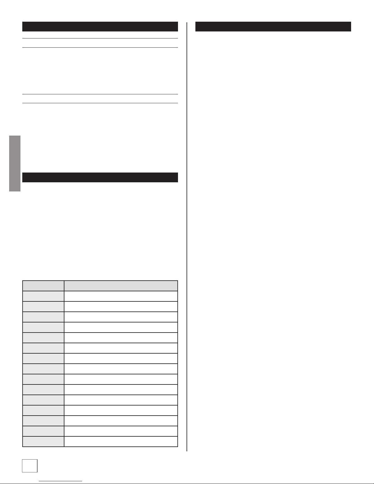
SPARE PARTS FOR THE PT17-XS
Support, but can be purchased from hobby shops or mail
order/Internet order rms. Hardware items (screws, nuts,
bolts) are also available from these outlets. If you need assistance locating a dealer to purchase parts, contact Product
Support.
KIT CHECK
Before starting to build, use the Kit Contents list to take an
inventory of this kit to make sure it is complete and inspect the
parts to make sure they are of acceptable quality. If any parts
are missing or are not of acceptable quality, or if you need assistance with assembly, contact Revell Product Support.
Service-Abteilung Revell GmbH
Henschelstr. 20-30, 32257 Bünde, Germany
Tel: 01805 110111 (nur für Deutschland) (Anrufkosten:
14 Cent/Min. a. d. dt. Festnetz; Mobilfunk max. 42 Cent/Min.)
Email: Hobbico-Service@Revell.de
For United States customers, please, contact :
Hobby Services
3002 N. Apollo Dr. Suite 1
Champaign IL 61822 USA
E-Mail: productsupport@hobbico.com
Service-Abteilung Revell GmbH
Henschelstr. 20-30, 32257 Bünde, Germany
Tel: 01805 110111 (nur für Deutschland)
(Anrufkosten: 14 Cent/Min. a. d. dt. Festnetz;
Mobilfunk max. 42 Cent/Min.)
Email: Hobbico-Service@Revell.de
Order n° Part name
FLWA4111 PT17-XS fuselage
FLWA4112 PT17-XS lower wing
FLWA4113 PT17-XS upper wing
FLWA4114 PT17-XS elevator
FLWA4115 PT17-XS rudder
FLWA4116 PT17-XS motor cowl
FLWA4117 PT17-XS main gear without wheels
FLWA4118 PT17-XS wing struts
FLWA4119 PT17-XS cockpit without pilot
FLWA4820 PT17-XS tail gear without wheel
FLWA4121 PT17-XS anodized spinner
FLWA4822 PT17-XS anodized prop
FLWA4823 PT17-XS brushless motor
FLWA4824 PT17-XS motor accessory set
FLWA4825 PT17-XS 40A ESC
4
Page 5

CONTENT OF DELIVERY
1
5
7
3
8
4
PART LIST
• 1. Fuselage with installed brushless motor and ESC, incl. anodized spinner and installed tail landing gear.
• 2. Set of main wings, painted and with all decals
• 3. Wing struts
• 4. Main gear
• 5. Rudder
• 6. Elevator
• 7. Accessory bag with levers and linkages and screw driver
• 8. Wing servos (installed)
6
2
ENGLISH
INSTALLING THE MAIN GEAR
❏ 1. Cut out the screws from the decal lm, using a sharp
hobby knife. Unscrew the 4 screws, xing the main gear slots.
❏ 2. Take away the plastic covering parts and put the gear
struts into the slots of the main gear holder of the fuselage.
5
Page 6

❏ 3. Put the plastic covers over the landing gear and x them
with 4 screws.
Take care, that the setscrews of the wheel collars are tightened.
ENGLISH
Otherwise take blue locking agent and tighten again.
ADDING THE WIND SHIELDS
❏ 1. Sand the wind shield a littgle bit on glueing area. Look,
that the shields are matching exactly to the body.
❏ 2. Also roughen the glueing area of the fuselage, using a
glass brush.
❏ 3. Then glue the wind shields with 5min. epoxy to the main
body. Also glue the pilot „Kurt“ to his seat.
INSTALLING THE TAIL UNIT
❏ 2. Install the levers on the aps of elevator and rudder
and adjust the linkage so, that servos and aps are in neutral
position.
If you put a little bit soap or vaseline to the screws, it is more easy
to screw it into. Also take care, to meet the holes on the opposite
plate of the rudder levers correctly.
MOUNTING THE MAIN WINGS
❏ 1. Put the fuselage upside down into a model stand. Put
the lower wing to the fuselage and x it with 2 screws.
❏ 1. Sand the splicing area and glue the elevator with 5min.
epoxy glue to the fuselage. Look for correct alignment and
x the elevator with pins until the glue is hardened. Srew the
tail wheel to the rudder, sand the body and the rudder at the
splicing area and glue it with 5min. epoxy to the fuselage.
6
❏ 2. Tighten the screws not to strong but strong enough.
Page 7

❏ 3. Cover the slots of the aileron servocables with
transparent adhesive tape.
MOUNTING THE UPPER WING
❏ 1. Before you can x the upper wing, you have to glue the
wing struts to the fuselage. All splice points are marked with
letters from A to F. Also you can nd these marks on the struts.
❏ 2. Roughen the splicing spots and keep them free of dust.
First glue the struts to the fuselage and wait until the epoxy
glue is hardened.
ENGLISH
❏ 3. For glueing the upper wing to the struts, take 30min.
epoxy glue, to have time enough, to t the wing exactly to
the body.
❏ 4. Fix the struts with clamps. Take balsa boards to avoid
dents of the clamps on wings upper side.
E
B
F
D
C
A
❏ 5. Bevore you remove the clamps, the epoxy glue should
be hardened completely.
❏ 6. Now the PT-17 assembling is nished and you can
continue with Rx installation.
7
Page 8

THROTTLE
GOES DOWN
4 CHANNELS SETUP
THROTTLE
GOES DOWN
4 CHANNELS SETUP
ENGLISH
RECEIVER INSTALLATION
GET THE MODEL READY TO FLY
CHECK THE CONTROL DIRECTIONS
❏ 1. Turn on the transmitter and receiver and center the
trims. If necessary, remove the servo arms from the servos and
reposition them so they are centered. Reinstall the screws that
hold on the servo arms.
❏ 2. With the transmitter and receiver still on, check all the
control surfaces to see if they are centered. If necessary, adjust
the clevises on the pushrods to center the control surfaces.
(STANDARD MODE 1)
RUDDER
GOES
RIGHT
LEFT AILERON
GOES DOWN
RIGHT AILERON
GOES UP
❏ 1. If you take o the magnetic holded cockpit, you have
space enough for placing the receiver.
On the picture above, you can see a sample installation of the
Tactic TR624 receiver. The receiver is xed with a doublesided
adhesive tape. Very important is, that the antenna of the
receiver is not crossing other cables. Always look for a clear
installation with free antenna, otherwise you will get receiving
troubles.
Use cable ties to put all free cables together.
BEFORE FLIGHT
The used 4s 2500 mAh battery should have at least 250g. If
you x this battery in the battery box with the velcro tape, the
C.G. should t automatically.
The C.G. is located 7,5 - 8,0 cm from the leading edge of the
middle of the upper wing. If you take the plane there, it should
be horizontal. Nose should be a little bit down.
ELEVATOR
FULL
(STANDARD MODE 2)
RUDDER
GOES
RIGHT
FULL
❏ 3. Make certain that the control surfaces and the carburetor
respond in the correct direction as shown in the diagram. If any
of the controls respond in the wrong direction, use the servo
reversing in the transmitter to reverse the servos connected to
those controls. Be certain the control surfaces have remained
centered. Adjust if necessary.
LEFT AILERON
GOES DOWN
RIGHT AILERON
GOES UP
ELEVATOR
8
Page 9

SET THE CONTROL THROWS
Use a ruler to accurately measure and set the control throw
of each control surface as indicated in the chart that follows.
If your radio does not have dual rates, we recommend setting
the throws at the low rate settings.
NOTE: The throws are measured at the widest part of the
elevators, rudder and ailerons.
Elevator Rudder Ailerons
+/- 10 mm +/- 25 mm +/- 15 mm
This setup is only a basic setup. Depending on your ight style,
you can increase or decrease the aps angle.
PREFLIGHT
IDENTIFY YOUR MODEL
No matter if you y at an AMA sanctioned R/C club site or if
you y somewhere on your own, you should always have your
name, address, telephone number and AMA number on or
inside your model. It is required at all AMA R/C club ying sites
and AMA sanctioned ying events. Fill out the identication
tag on the decal sheet and place it on or inside your model.
BALANCE PROPELLERS
We recommend, to balance the propeller very carefully.
Balanced propellers are very silent and have more thrust. Also
you protect the bearings of the motor.
ENGLISH
GROUND CHECK
Before ight inspect the model to make sure all screws remained tight, the hinges are secure, the prop is secure and all
pushrods and connectors are secure. Also check the landing
gear after every ight.
CHARGE THE BATTERIES
Follow the battery charging instructions that came with your
radio control system to charge the batteries. You should always
charge your transmitter and receiver batteries the night before
you go ying and at other times as recommended by the radio
manufacturer.
NOTE: Checking the condition of your receiver battery pack is
highly recommended. All battery packs, whether it's a trusty
pack you've just taken out of another model, or a new battery
pack you just purchased, should be cycled, noting the discharge
capacity. Oftentimes, a weak battery pack can be identied
(and a valuable model saved!) by comparing its actual capacity
to its rated capacity. Refer to the instructions and recommendations that come with your cycler. If you don't own a battery
cycler, perhaps you can have a friend cycle your pack and note
the capacity for you. gemessenen. Hier können große Unterschiede auftreten.
RANGE CHECK
Ground check the operational range of your radio before the
rst ight of the day. With the transmitter antenna collapsed
and the receiver and transmitter on, you should be able to
walk at least 100 feet away from the model and still have
control. Have an assistant stand by your model and, while
you work the controls, tell you what the control surfaces are
doing. Repeat this test with the engine running at various
speeds with an assistant holding the model, using hand signals to show you what is happening. If the control surfaces do
not respond correctly, do not y! Find and correct the problem
rst. Look for loose servo connections or broken wires, corroded wires on old servo connectors, poor solder joints in your
battery pack or a defective cell, or a damaged receiver crystal
from a previous crash.
9
Page 10

ENGINE SAFETY PRECAUTIONS
Failure to follow these safety precautions may result
in severe injury to yourself and others.
❍ Adjust the fail safe of your radio system so, that on signal
lost the motor is powered down immediately.
❍ Program a motor safety switch on your transmitter, if
possible.
❍ Do not run the engine in an area of loose gravel or sand;
the propeller may throw such material in your face or
eyes.
❍ Keep your face and body as well as all spectators away
from the plane of rotation of the propeller as you start
and run the engine.
❍ Keep these items away from the prop: loose clothing,
shirt sleeves, ties, scarfs, long hair or loose objects such as
pencils or screwdrivers that may fall out of shirt or jacket
pockets into the prop.
❍ The engine can be hot after use. Do not touch after
ENGLISH
operation.
❍ After ight bring the plane in a safe position
CHECK-LIST
During the last few moments of preparation your mind may
be elsewhere anticipating the excitement of the rst ight.
Because of this, you may be more likely to overlook certain
checks and procedures that should be performed before
the model is own. To help avoid this, a checklist is provided
to make sure these important areas are no overlooked.
Many are covered in the instruction manual, so where
appropriate, refer to the manual for complete instructions.
Be sure to check the items o as they are completed (that's
why it's called a check list!).
❍ 1. Check the C.G. according to the measurements
provided in the manual.
❍ 2. Be certain the battery and receiver are securely
mounted in the fuse. Simply stung them into place with
foam rubber is not sucient.
❍ 3. Look for a correct position of your receiver antenna or
antennas. The antenna should not be ´close to other wires
inside the fuselage.
❍ 4. Balance your model laterally as explained in the
instructions.
❍ 5. Use threadlocking compound to secure critical
fasteners such as the set screws that hold the wheel
axles to the struts, screws that hold the carburetor arm (if
applicable), screw-lock pushrod connectors, etc.
❍ 6. Add a drop of oil to the axles so the wheels will turn
freely.
❍ 7. Make sure all hinges are securely glued in place.
❍ 8. Reinforce holes for wood screws with thin CA where
appropriate (servo mounting screws, cowl mounting
screws, etc.).
❍ 9. Conrm that all controls operate in the correct direction
and the throws are set up according to the manual.
❍ 10. Make sure there are silicone retainers on all the
clevises and that all servo arms are secured to the servos
with the screws included with your radio.
❍ 11. Secure connections between servo wires and Y
connectors or servo extensions and the connection
between your battery pack and the on/o switch with
vinyl tape, heat shrink tubing or special clips suitable for
that purpose.
10
❍ 12. Make sure any servo extension cords you may have
used do not interfere with other systems (servo arms,
pushrods, etc.).
Page 11

❍ 13. Secure the pressure tap (if used) to the muer with
high temp RTV silicone, thread locking compound or
J.B.Weld.
❍ 14. Balance your propeller (and spare propellers).
❍ 15. Tighten the propeller nut and spinner.
❍ 16. Place your name, address, AMA number and
telephone number on or inside your model.
❍ 17. Cycle your receiver battery pack (if necessary) and
make sure it is fully charged.
❍ 18. If you wish to photograph your model, do so before
your rst ight.
❍ 19. Range check your radio when you get to the ying
eld.
PERSONAL NOTES
Remember to think.
Have a ball!
But always stay in control and y in
a safe manner.
GOOD LUCK AND
GREAT FLYING!
ENGLISH
11
Page 12

ENGLISH
Distributed by
12
www.hobbico.de
 Loading...