

Page 1
BUILDING AND INSTRUCTION MANUAL
FLWA4003 - Extra 300 LP ARF
V3
78150
Fully licensed through the
Red Bull GmbH - Austria
Wing load
Wingspan 1700 mm
Length 1570 mm
Take o weight 3770 g
Wing area 50.2 dm²
Wing load 75 g/dm²
Electric drive set FW 5065
Gas engine 25-30 ccm
Please read the instruction manual carefully and take notice of the safety guidelines.
If the model is given to a third party, always include this instruction manual to the model
Version 1.00
Distributed by
www.hobbico.de
Page 2
TABLE OF CONTENTS
General informations ...................................................................... 2
Environment protection infos ....................................................2
Introduction ........................................................................................ 3
Safety precautions ........................................................................... 3
Recommended accessories ..........................................................4
Additional items required ............................................................4
Hardware and Accessories ........................................................4
Covering Accessories ..................................................................4
Adhesives and Building Supplies ............................................ 4
Optional Supplies and Tools ..................................................... 4
Kit check ................................................................................................ 4
Spare parts ........................................................................................... 4
Fitting the landing gear: ................................................................ 5
Rudder assembling .......................................................................... 6
Assembling of the elevator ..........................................................7
Installation of the electric drive set ......................................... 7
ENGLISH
backmount version .......................................................................... 7
Wing assembly ...................................................................................8
Secure the canopy ............................................................................ 9
Nitro and gas engines ..................................................................... 9
Nitro engines ..................................................................................9
Gas engines ................................................................................. 10
Tank assembling and installation ........................................ 11
Template for the Flitework
Motorsets (008-5060/65) ........................................................ 11
RC components ............................................................................... 12
Get the model ready to y ......................................................... 12
Check the Control Directions ................................................ 12
Balance the Model (C.G.) ......................................................... 12
Balance the Model Laterally .................................................. 13
Set the Control Throws ............................................................ 13
Preight .............................................................................................. 14
Charge the Batteries ................................................................. 14
Balance Propellers ..................................................................... 14
Ground Check ............................................................................. 14
Range check ................................................................................ 14
Engine safety precautions ........................................................ 15
Check-List .......................................................................................... 15
GENERAL INFORMATIONS
• Read this manual and its safety precautions carefully! Keep this manual and if
you give the model to a third party, put this manual to the model.
• Take care, that you are familiar with your transmitter and all electronic
components, used in your plane.
• Take care of all safety instructions of tools, which are you using to assemble
this model.
• Only take glues, which are recommended for the specic materials and which
are approved for model business.
• Before assembling please check all parts of this kit. If some parts are missing or
have a mistake, please call.
2
ENVIRONMENT PROTECTION INFOS
• The symbols on the package show you, that the model
and its accessories should not be put to waste. All electric
and electronic parts should be deposed to places of
waste management.
• Batteries and accumulators must
be removed from the devices and
should be deposed to the correct
waste management organisation. Take
information from your home town
government.
Page 3

Introduction
Congratulations for purchasing the Flitework Extra 300LP. We say thanks for your trust and we wish you a lot of happy
ights with your new Extra 300 LP.
The Extra 300LP is one of the best aerobatic planes in the world. The competition pilots of the Flying Bulls commit this
versions very successful in dierent contests.
Also the Flitework Extra 300 is one of the best aerobatic and 3D models in this class. And we wish you a lot of pleasure
with this model.
Attention please!
Remote controlled model planes are not a toy! For assembling, ying and servicing such models, you need a high
grade of technical comprehension and liability.
Careless assembling and operation may cause personal and material damage.
Because the Flitework GmbH has no inuence on assembly, RC installation, operation and servicing of the ight
device, any liability is rejected under explicit advice to these dangers.
ENGLISH
SAFETY PRECAUTIONS
1. Your Extra 300 LP should not be considered a toy, but rather
a sophisticated, working model that functions very much like
a full-size airplane. Because of its performance capabilities, the
Extra 300 LP, if not assembled and operated correctly, could
possibly cause injury to yourself or spectators and damage to
property.
2.You must assemble the model according to the instructions.
Do not alter or modify the model, as doing so may result in a
unsafe or unyable model. In a few cases the instructions may
dier slightly from the photos. In those instances the written
instructions should be considered as correct.
3. You must take time to build straight, true and strong.
4. You must use an R/C radio system that is in rst-class
condition and a correctly sized engine and components (fuel
tank, wheels, etc.) throughout the building process.
5. You must correctly install all R/C and other components so
that the model operates correctly on the ground and in the air.
6. You must check the operation of the model before every
ight to insure that all equipment is operating and that the
model has remained structurally sound. Be sure to check
clevises or other connectors often and replace them if they
show any signs of wear or fatigue.
7. If you are not already an experienced R/C pilot, you should
y the model only with the help of a competent, experienced
R/C pilot.
8. While this kit has been ight tested to exceed normal use,
if the plane will be used for extremly hight stress ying, such
as racing, or if an engine larger than one in the recommended
range is used, the modeler is responsible for taking steps to
reinforce the hight stress points and/or substituting hardware
more suitable for the increased stress.
8. WARNING: The cowl and wheel pants included in this kit
are made of berglass, the bers of which may cause eye,
skin and respiratory tract irritation. Never blow into a part to
remove berglass dust, as the dust will blow back into your
eyes. Always wear safety goggles, a particle mask and rubber
gloves when grinding, drilling and sanding berglas parts.
Vacuum the parts and work area thoroughly after working
with berglass parts.
Flitework quatily
We, as the kit manufacturer, provide you with a top quality kit and instructions, but ultimately the quality and yability of your
nished model depends on how you build it; therefore, we cannot in any way guarantee the performance of your completed
model and no representations are expressed or implied as to the performance or safety of your completed model.
3
3
Page 4

RECOMMENDED ACCESSORIES
This is a partial list of items required to nish the Extra 300 LP
V3 that may require planning or decision-making before starting to build. Order numbers are provided in parentheses.
❍ 1 x Motorset FW 5065 order no.: FLWA8007
❍ 2 x Aileronservos order no.: 007-4020M
❍ 2 x Rudder- and elevator servos order no.: 007-4020M
❍ 1 x Lipo-Akku 6s 4000mAh 20C order no.: 018-4006
❍ 1 x 5-6 channel receiver
❍ 4 x Servo cable extensions
ADDITIONAL ITEMS REQUIRED
HARDWARE AND ACCESSORIES
In addition to the items listed in the “Decisions You Must
Make” section, following is the list of hardware and accessories
ENGLISH
required to nish the Extra 300 LP V3. Order numbers are
provided in parentheses.
❍ Hook & Loop Velcro (GPMQ4480)
❍ 3' Medium fuel tubing (GPMQ4131)
❍ Easy Fueler™ fuel lling valve for glow fuel (GPMQ4160)
❍ Handy Mounts air valve, fuel ller mounts (GPMQ6000)
COVERING ACCESSORIES
❍ 21st Century® sealing iron (COVR2700)
❍ 21st Century trim seal iron (COVR2750)
❍ 21st Century iron cover (COVR2702)
ADHESIVES AND BUILDING SUPPLIES
In addition to common household tools and hobby tools, this
is the “short list” of the most important items required to build
the Extra 300 LP V3. Great Planes Pro™ CA and Epoxy glue are
recommended.
❍ 1/2 oz. Thin Pro CA (GPMR6001)
❍ 1/2 oz. Medium Pro CA+ (GPMR6007)
❍ 6-Minute Epoxy (GPMR6045)
❍ 30-Minute Epoxy (GPMR6047)
❍ Small T-pins (HCAR5100)
❍ Electric drill
❍ Drill bit set including (1/16" 3/32" 1/8" 5/64" and 1/2" bits)
❍ Small Phillips and at blade screwdrivers (HCAR1040)
❍ Pliers with wire cutter (HCAR0630)
❍ Standard Hex wrench set (HCAR0520)
OPTIONAL SUPPLIES AND TOOLS
Here is a list of optional tools mentioned in the manual that
will help you build theExtra 300 LP V3.
❍ Great Planes CG Machine™ (GPMR2400)
❍ Top Flite® Precision Magnetic Prop Balancer™ (TOPQ5700)
❍ Straightedge with scale (HCAR0475)
❍ Cutting mat (HCAR0456)
❍ Masking Tape (TOPR8018)
❍ CA Applicator Tips (GPMR6033)
❍ CA Debonder (GPMR6039)
❍ CA Accelerator (GPMR6034)
❍ Milled Fiberglass (GPMR6165)
❍ Microballoons (TOPR1090)
❍ Epoxy Brushes (GPMR8060)
❍ Mixing Sticks (GPMR8055)
❍ Threadlocker (GPMR6060)
❍ Denatured Alcohol (for epoxy clean up)
❍ Hobby Knife (HCAR0105), #11 Blades (HCAR0211)
❍ Non-elastic monolament or Kevlar shing line (for stab
❍ alignment)
❍ Builders Triangle Set (HCAR0480) (for n alignment)
❍ Easy-Touch™ Bar Sander (GPMR6170, or similar)
❍ Felt-Tip Marker (TOPQ2510)
❍ Small metal le
❍ Rotary tool such as Dremel®
❍ Rotary tool reinforced cut-o wheel (GPMR8200)
❍ Curved Tip Canopy Scissors for trimming plastic parts
❍ (HCAR0667)
❍ Dead Center™ Engine Mount Hole Locator (GPMR8130)
❍ Great Planes AccuThrow™ Deection Gauge (for
❍ measuring control throws, GPMR2405)
KIT CHECK
Before starting to build, use the Kit Contents list to take an
inventory of this kit to make sure it is complete and inspect the
parts to make sure they are of acceptable quality. If any parts
are missing or are not of acceptable quality, or if you need assistance with assembly, contact Revell Product Support.
Service-Abteilung Revell GmbH
Henschelstr. 20-30, 32257 Bünde, Germany
Tel: 01805 110111 (nur für Deutschland) (Anrufkosten:
14 Cent/Min. a. d. dt. Festnetz; Mobilfunk max. 42 Cent/Min.)
Email: Hobbico-Service@Revell.de
SPARE PARTS
Support, but can be purchased from hobby shops or mail
order/Internet order rms. Hardware items (screws, nuts,
bolts) are also available from these outlets. If you need assistance locating a dealer to purchase parts, contact Product
Support.
Service-Abteilung Revell GmbH
Henschelstr. 20-30, 32257 Bünde, Germany
Tel: 01805 110111 (nur für Deutschland)
(Anrufkosten: 14 Cent/Min. a. d. dt. Festnetz;
Mobilfunk max. 42 Cent/Min.)
Email: Hobbico-Service@Revell.de
4
Page 5
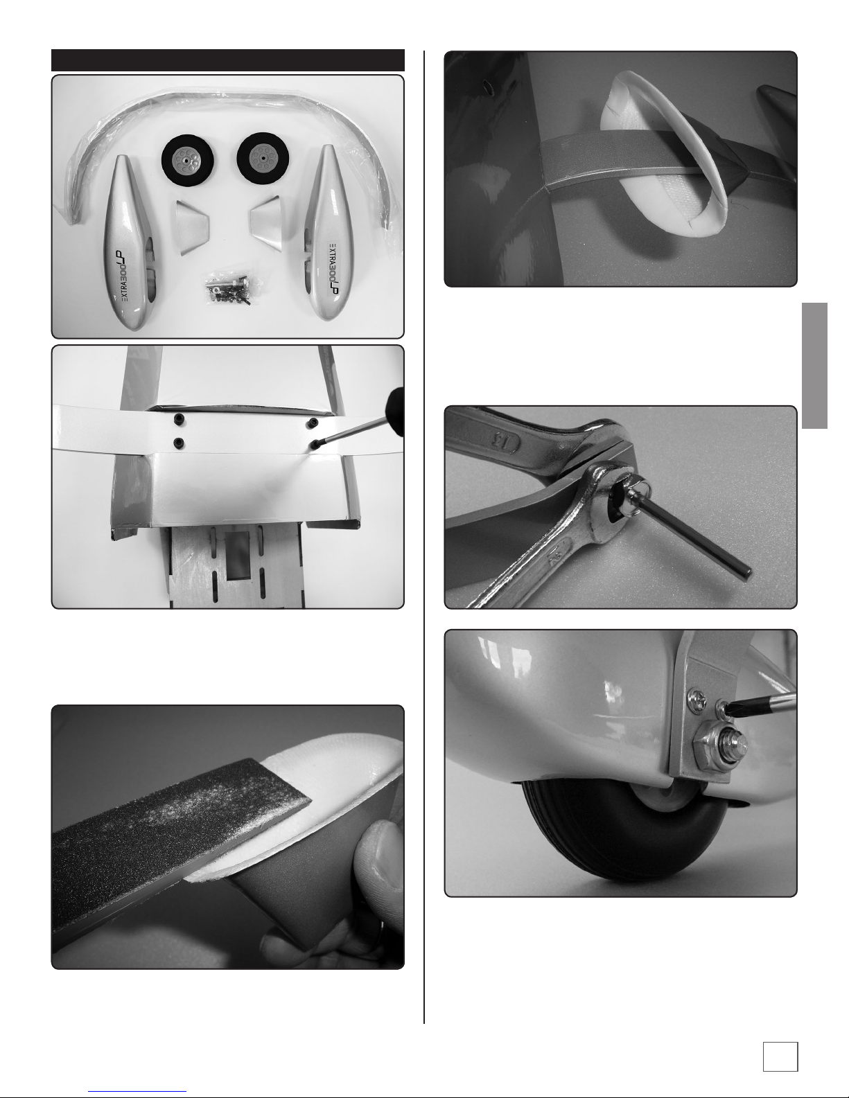
FITTING THE LANDING GEAR:
Fit the fairings close to the fuselage. Use sandpaper or a le to
adapt the correct mounting angle. Put the fairings along the
hangers to the body and x with double sided adhesive tape
or use the 2 mm screws for fastening.
ENGLISH
The landing gear is a stable aluminium construction. For
mounting put the landing gear into the slot of the fuselage
and x it, using the 4 pcs of M4x20 screws. Use blue locking
agent!
Now put the wheel hub into the hanger and x with the 8 mm
locknut. Take care, that the edges of the nut are parallel to the
hanger. This is important to place the wheel pants correctly.
With the 2 collars you can x the wheels. After mounting
the wheels you can screw the wheel pants towards the gear
hangers. Take care of the parallel direction of the wheel pants.
5
Page 6

ENGLISH
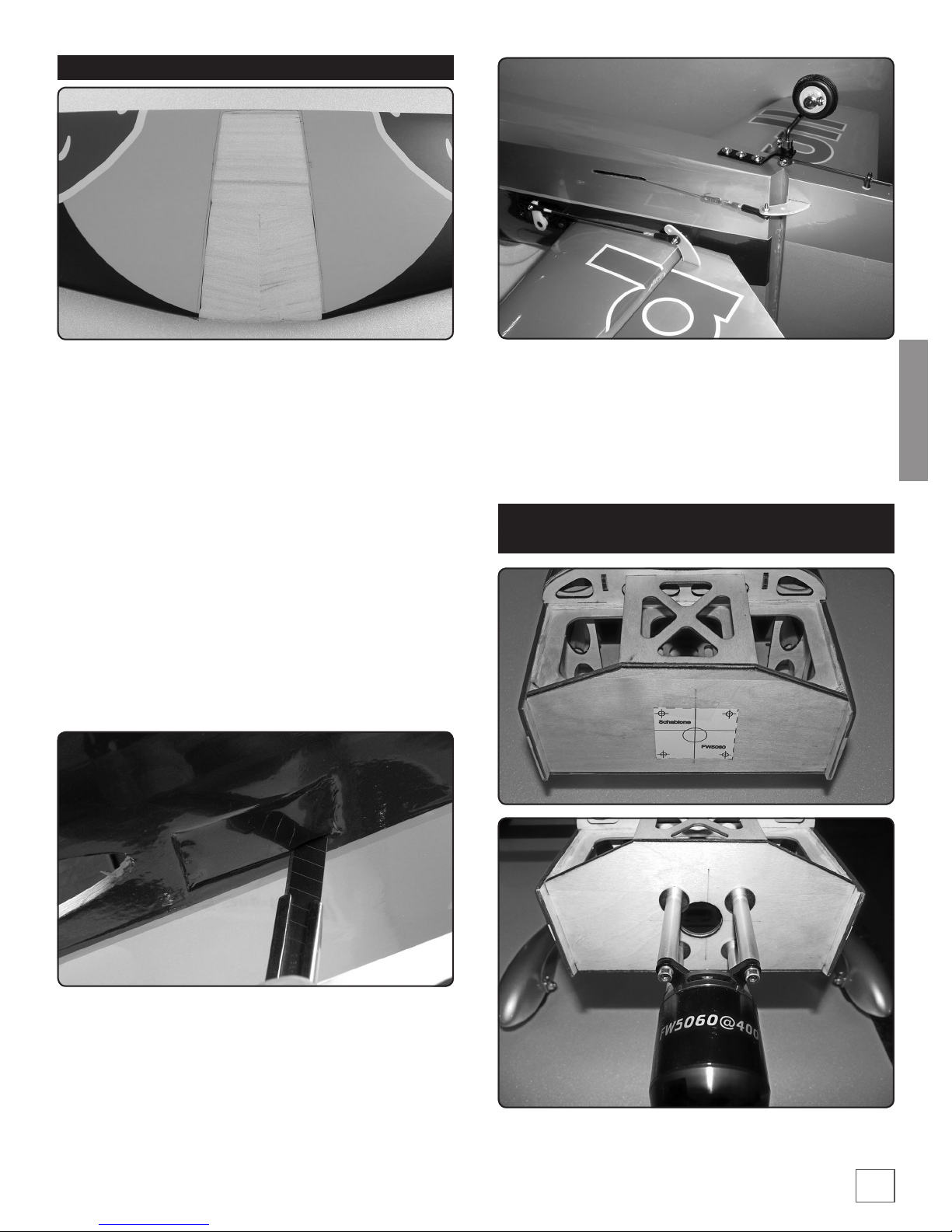
RUDDER ASSEMBLING
Now you can glue the rudder into the slots of fuselage.
Assemble the tail gear like shown in the pictures below and
mount to the fuselage using 3 wood screws. The pivot points
of rudder and tail gear should be the same. About 5 cm away
from the pivot point drill a 4-4.5 mm hole. Thread the ball
head on the steel pin and glue the ball head into the rudder.
Put the rudder into max. position and shorten the steel pin
1 cm after the ball head. Put the eyescrews halfway into the
ball link and x the ball link with M2 screws to the servo lever.
Mount the steering wire like in the picture. The steering wires
should be mounted crossed over inside the fuselage. Fix the
steering wire to the rudder lever in the same way like servo
lever. The wires should have a small tension and there should
be no gap in neutral rudder position.
Feel out the slots under the covering lm and open them
with a hobby knife. Try the matching of the rudder lever and
correct with a le if necessary. Glue the lever with 10 min
epoxy into the slot, taking care of a symmetric position of the
lever. Afterwards put the hinges into the rudder, using very
thin CA or PVA glue. If the slots for hinges are to close, open it
with a hobby knife.
6
Page 7
ASSEMBLING OF THE ELEVATOR
Put the elevator unit into the fuselage and adjust carefully.
Take a thin non permanent marker and make a line along the
fuselage on both sides onto the elevator unit. Put away the
covering lm a little bit inside the lines, using a very sharp
hobby knife. Take care and do not hurt the balsa wood under
the covering. If you like to use only one elevator servo, it is
very important, to put the steel connector rst into the correct
position in the body. Then glue the elevator unit with 10 min.
Epoxy into the fuselage. Afterwards glue the hinges into the
elevator ns, using very thin CA or PVA glue. Together with
the hinges glue the steel connector to the elevator unit. We
recommend, to roughen the steel part, which is glued into
the elevator n, with sand paper. Make the same procedure
on other side of elevator. Look at the exact position of both
elevator ns. The ns should be not distorted!! After opening
the slot in the elevator n you can glue the elevator lever into
the slot, using epoxy glue.
Open the servo frame in front of the elevator unit.
If you use one elevator servo, we recommend the Flitework
4020M servo with 90N/cm traction force. (Order no.: 0074020M) If you use 2 servos for elevator, we recommend
2 pcs of Flitework 3615 servos. (Order no.: 007-3615) The
servo levers should have 25 mm from pivot point of servo to
mounting point of ball link to have a elevator range of +/- 45°
for 3D ight.
INSTALLATION OF THE ELECTRIC DRIVE SET
BACKMOUNT VERSION
ENGLISH
Cutout the drilling template from the end of this manual and
x with adhesive tape against the rewall*.
7
Page 8

ENGLISH
WING ASSEMBLY
Then, attach the aluminium spacers to the rewall using
washers on both sides of the rewall and SHSC 4 x 20 mm
screws. Add a drop of threadlocker compound ont the screws.
Note that inner washers need to be cut to clear the triangular
spars.
The ESC will be secured as shown using Tie-Raps. The ESC
cables will be routed alog the fuse anges to clear space for
the battery pack.
Fit the ailerons to the wings like rudder and elevator, using thin
CA or PVA glue. Be carefully, because CA glue can make ugly
tracks on the surface of the wing. Feel out the slots for aileron
levers and open with sharp hobby knife. Glue the levers into
the aileron ns with 10 min. Epoxy. Put the aileron servos into
the servo frames and x with wood screws. For 3D ight the
levers should have a length of 30 mm. We recommend the
Flitework carbon bre servo lever set for Extra 300 LP (Order
no.:007-902)
8
Page 9

SECURE THE CANOPY
For extrem 3D ight, please secure the canopy using screws.
Holes are made in the fuse, you just have tu drill holes in the
canopy frame and to add a nut. An other way may be to t a
2/2.2 mm carbon rod in the holes.
NITRO AND GAS ENGINES
As a wide range of gas engine can be tted on the Extra, the se
instructions are only informative and each user will dene the
exact way to install his engine.
NITRO ENGINES
For the Extra 300 LP, we suggest to use a two strokes .120 ci
engine or a four strokes .140 ci engine
You can mount the attached motor holder directly to the
rewall frame. The distance between the motor holders is
dependent on the used nitro engine.
The side pull of the motor is basically integrated in the rewall
frame. If the side pull or the motor inclination is not correct,
you can adjust with shims.
Its better to make a template from paper for mounting the
specic engine. The cross mark on the rewall indicates the
center of the motor axis.
ENGLISH
9
Page 10

ENGLISH
To keep the scale design of the cowling, the engine should be
mounted hanging with cylinder down. On the lower side of
the cowling cut out openings for the exhaust system and for
cooling air circulation.
GAS ENGINES
Gas engines from 26 ccm and more are very easy to x, because
they mostly have a back mount system We recommend to use
the DLE 30 engine. (Order no.: 008-DLE30)
Similar to the nitro engine mounting you use the cross mark
on rewall for correct engine orientation. Also it is useful to
make a paper template from the mounting points of the used
gas engine.
10
Like nitro engines were gas engines built in hanging position.
You also have to cut out the openings for muer and cooling
air stream.
The throttle servo can be mounted on the lower side of the
motor dome.
Page 11

TANK ASSEMBLING AND INSTALLATION
Check the leakproofness of the tank and x it in the shown
position with zip ties. Use some damping material under the
tank, that the vibrations of the motor cannot reach the tank
unabated. Vibrations may cause foamy fuel and therefore
unstable motor operation.
ENGLISH
TEMPLATE FOR THE FLITEWORK
MOTORSETS (008-5060/65)
First you should bend the aluminium tubes in an angle of 40°.
Then install the tubes into the sealing plug as shown in the
pictures below.
11
Page 12

RC COMPONENTS
MOVES DOWN
4-CHANNEL RADIO SETUP
MOVES DOWN
4-CHANNEL RADIO SETUP
(MODE 1)
ENGLISH
RUDDER
MOVES
RIGHT
ELEVATOR
(MODE 2)
RIGHT AILERON MOVES UP
LEFT AILERON MOVES DOWN
RIGHT AILERON MOVES UP
LEFT AILERON MOVES DOWN
CARBURETOR WIDE OPEN
RUDDER
MOVES
RIGHT
Der 6s 4000 Akku lässt sich mit Akkubändern (BestNr.: 008-
502) sicher im Bug des Rumpfes verankern. Wir empfehlen
unter dem Akku eine Antirutschmatte mit doppelseitiger
Klebefolie zu befestigen.
Vor dem Seitenruderservo ist ausrei-chend Platz, die
Empfangsanlage unterzubringen. Für die Querruderservos
sind zwei Servokabelverlängerungen von 10 cm Länge
ausreichend.
GET THE MODEL READY TO FLY
❏ 1. Turn on the transmitter and receiver and center the
trims. If necessary, remove the servo arms from the servos and
reposition them so they are centered. Reinstall the screws that
hold on the servo arms.
❏ 2. With the transmitter and receiver still on, check all the
control surfaces to see if they are centered. If necessary, adjust
the clevises on the pushrods to center the control surfaces.
CHECK THE CONTROL DIRECTIONS
ELEVATOR
CARBURETOR WIDE OPEN
❏ 3. Make certain that the control surfaces and the carburetor
respond in the correct direction as shown in the diagram. If any
of the controls respond in the wrong direction, use the servo
reversing in the transmitter to reverse the servos connected to
those controls. Be certain the control surfaces have remained
centered. Adjust if necessary.
BALANCE THE MODEL (C.G.)
More than any other factor, the C.G. (balance point) can
have the greatest e ect on how a model ies and may
determine whether or not your rst ight will be successful.
If you value this model and wish to enjoy it for many ights,
DO NOT OVERLOOK THIS IMPORTANT PROCEDURE. A
model that is not properly balanced will be unstable and
possibly un yable.
12
Page 13
At this stage the model should be in ready-to-y condition
with all of the systems in place including the engine, landing
gear, covering and the radio system.
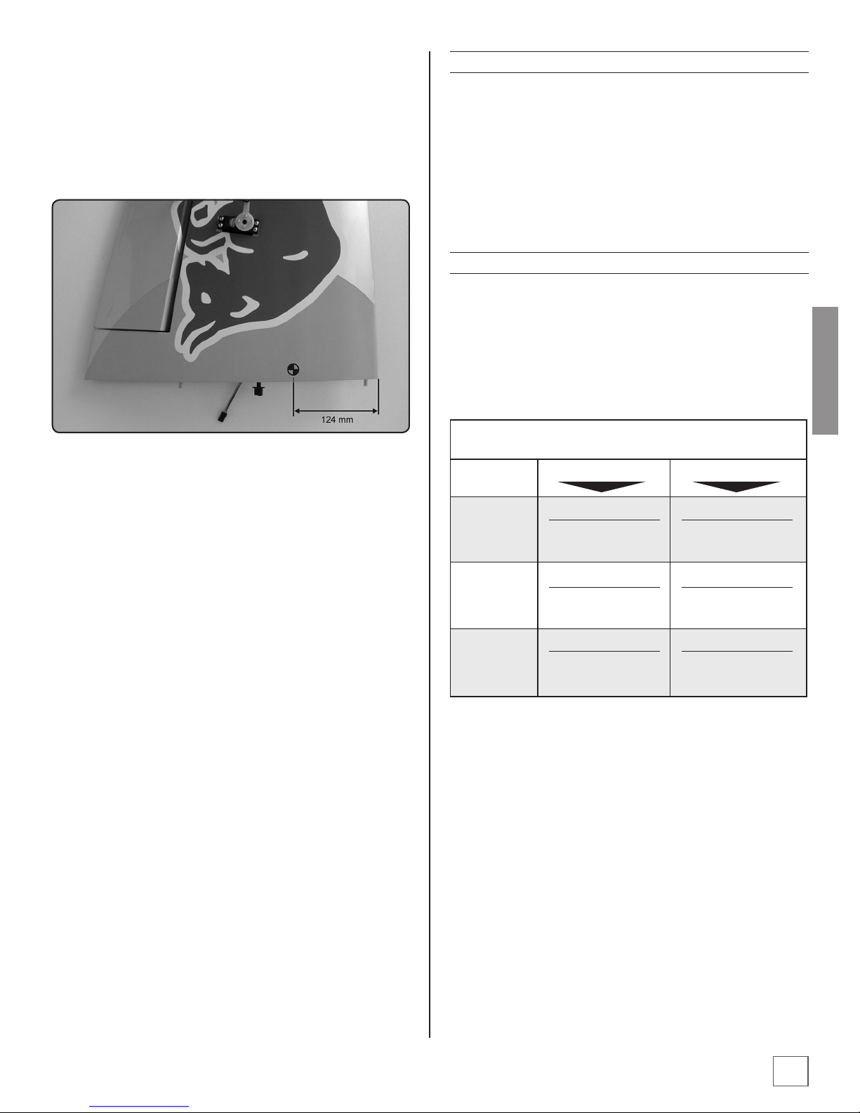
❏ 1. Use a felt-tip pen or 1/8"-wide tape to accurately mark
the C.G. on the top of the wing. The C.G. is located 4-7/8"
[124mm] back from the leading edge of the wing.
❏ 2. With the wing attached to the fuselage, all parts of the
model installed (ready to y) and an empty fuel tank, place
the model upside-down on a Great Planes CG Machine, or lift
it upside-down at the balance point you marked.
❏ 3. If the tail drops, the model is “tail heavy” and the battery
pack and/or receiver must be shifted forward or weight must
be added to the nose to balance. If the nose drops, the model
is “nose heavy” and the battery pack and/or receiver must be
shifted aft or weight must be added to the tail to balance. If
possible, relocate the battery pack and receiver to minimize or
eliminate any additional ballast required. If additional weight is
required, nose weight may be easily added by using a “spinner
weight” (GPMQ4645 for the 1 oz. weight, or GPMQ4646 for the
2 oz. weight). If spinner weight is not practical or is not enough,
use Great Planes (GPMQ4485) “stick-on” lead. A good place to
add stick-on nose weight is to the rewall (don't attach weight
to the cowl–it is not intended to support weight). Begin by
placing incrementally increasing amounts of weight on the
bottom of the fuse over the rewall until the model balances.
Once you have determined the amount of weight required, it
can be permanently attached. If required, tail weight may be
added by cutting open the bottom of the fuse and gluing it
permanently inside.
BALANCE THE MODEL LATERALLY
❏ 1. With the wing level, have an assistant help you lift the
model by the engine propeller shaft and the bottom of the
fuse under the TE of the n. Do this several times.
❏ 2. If one wing always drops when you lift the model, it
means that side is heavy. Balance the airplane by adding
weight to the other wing tip. An airplane that has been laterally
balanced will track better in loops and other maneuvers.
SET THE CONTROL THROWS
Use a ruler to accurately measure and set the control throw of
each control surface as indicated in the chart that follows. If
your radio does not have dual rates, we recommend setting
the throws at the low rate settings.NOTE: The throws are measured at the widest part of the elevators, rudder and ailerons.
We recommend the following control surface throws:
3D Control Throws Low rate
Elevator
Rudder
Ailerons
Up
40°
Expo 45%
Left
45°
Expo 45%
Up
40°
Expo 45%
Down
40°
Expo 45%
Right
45°
Expo 45%
Down
40°
Expo 45%
Up
20°
Expo 25%
Left
30°
Expo 30%
Up
20°
Expo 25%
Down
20°
Expo 25%
Right
30°
Expo 30%
Down
20°
Expo 25%
ENGLISH
Note: Do not rely upon the adhesive on the back of the
lead weight to permanently hold it in place. Over time, fuel
and exhaust residue may soften the adhesive and cause the
weight to fall o. Use #2 sheet metal screws, RTV silicone or
epoxy to permanently hold the weight in place.
❏ 4. IMPORTANT: If you found it necessary to add any weight,
recheck the C.G. after the weight has been installed.
13
Page 14

PREFLIGHT
CHARGE THE BATTERIES
Follow the battery charging instructions that came with your
radio control system to charge the batteries. You should always
charge your transmitter and receiver batteries the night before
you go ying and at other times as recommended by the radio
manufacturer.
NOTE: Checking the condition of your receiver battery pack is
highly recommended. All battery packs, whether it's a trusty
pack you've just taken out of another model, or a new battery
pack you just purchased, should be cycled, noting the discharge
capacity. Oftentimes, a weak battery pack can be identied (and
a valuable model saved!) by comparing its actual capacity to its
rated capacity. Refer to the instructions and recommendations
that come with your cycler. If you don't own a battery cycler,
perhaps you can have a friend cycle your pack and note the
ENGLISH
capacity for you. gemessenen. Hier können große Unterschiede
auftreten.
BALANCE PROPELLERS
all screws remained tight, the hinges are secure, the prop is
secure and all pushrods and connectors are secure.
RANGE CHECK
Ground check the operational range of your radio before the
rst ight of the day. With the transmitter antenna collapsed
and the receiver and transmitter on, you should be able to
walk at least 100 feet away from the model and still have
control. Have an assistant stand by your model and, while
you work the controls, tell you what the control surfaces are
doing. Repeat this test with the engine running at various
speeds with an assistant holding the model, using hand signals to show you what is happening. If the control surfaces do
not respond correctly, do not y! Find and correct the problem
rst. Look for loose servo connections or broken wires, corroded wires on old servo connectors, poor solder joints in your
battery pack or a defective cell, or a damaged receiver crystal
from a previous crash.
Carefully balance your propeller and spare propellers before
you y. An unbalanced prop can be the single most signicant
cause of vibration that can damage your model. Not only will
engine mounting screws and bolts loosen, possibly with
disastrous eect, but vibration may also damage your radio
receiver and battery. Vibration can also cause your fuel to
foam, which will, in turn, cause your engine to run hot or quit
We use a Top Flite® Precision Magnetic Prop Balancer™
(TOPQ5700) in the workshop and keep a Great Planes Fingertip Prop Balancer (GPMQ5000) in our ight box.
GROUND CHECK
If the engine is new, follow the engine manufacturer's instructions to break-in the engine. After break-in, conrm that the
engine idles reliably, transitions smoothly and rapidly to full
power and maintains full powerindenitely. After you run the
engine on the model, inspect the model closely to make sure
14
Page 15

ENGINE SAFETY PRECAUTIONS
Failure to follow these safety precautions may result in
severe injury to yourself and others.
❍ Keep all engine fuel in a safe place, away from high heat,
sparks or ames, as fuel is very ammable. Do not smoke
near the engine or fuel; and remember that engine
exhaust gives o a great deal of deadly carbon monoxide.
Therefore do not run the engine in a closed room or
garage.
❍ Get help from an experienced pilot when learning to
operate engines.
CHECK-LIST
During the last few moments of preparation your mind may
be elsewhere anticipating the excitement of the rst ight.
Because of this, you may be more likely to overlook certain
checks and procedures that should be performed before
the model is own. To help avoid this, a checklist is provided
to make sure these important areas are no overlooked.
Many are covered in the instruction manual, so where
appropriate, refer to the manual for complete instructions.
Be sure to check the items o as they are completed (that's
why it's called a check list!).
❍ Use safety glasses when starting or running engines.
❍ Do not run the engine in an area of loose gravel or sand;
the propeller may throw such material in your face or
eyes.
❍ Keep your face and body as well as all spectators away
from the plane of rotation of the propeller as you start
and run the engine.
❍ Keep these items away from the prop: loose clothing,
shirt sleeves, ties, scarfs, long hair or loose objects such as
pencils or screwdrivers that may fall out of shirt or jacket
pockets into the prop.
❍ Use a “chicken stick” or electric starter to start the engine.
❍ Do not use your ngers to ip the propeller.Make certain
the glow plug clip or connector is secure so that it will not
pop o or otherwise get into the running propeller.
❍ Make all engine adjustments from behind the rotating
propeller.
❍ The engine gets hot! Do not touch it during or right after
operation. Make sure fuel lines are in good condition so
fuel will not leak onto a hot engine, causing a re.
❍ To stop a glow engine, cut o the fuel supply by closing
o the fuel line or following the engine manufacturer's
recommendations. Do not use hands, ngers or any
other body part to try to stop the engine. Do not throw
anything into the propeller of a running engine.
❍ 1. Fuelproof all areas exposed to fuel or exhaust residue
such as the cowl ring, cowl mounting blocks, wing saddle
area, etc.
❍ 2. Check the C.G. according to the measurements
provided in the manual.
❍ 3. Be certain the battery and receiver are securely
mounted in the fuse. Simply stung them into place
with foam rubber is not sucient.
❍ 4. Extend your receiver antenna and make sure it has a
strain relief inside the fuselage to keep tension o the
solder joint inside the receiver.
❍ 5. Balance your model laterally as explained in the
instructions.
❍ 6. Use threadlocking compound to secure critical
fasteners such as the set screws that hold the wheel
axles to the struts, screws that hold the carburetor arm (if
applicable), screw-lock pushrod connectors, etc.
❍ 7. Add a drop of oil to the axles so the wheels will turn
freely.
❍ 8. Make sure all hinges are securely glued in place.
❍ 9. Reinforce holes for wood screws with thin CA where
appropriate (servo mounting screws, cowl mounting
screws, etc.).
❍ 10. Conrm that all controls operate in the correct
direction and the throws are set up according to the
manual.
❍ 11. Make sure there are silicone retainers on all the
clevises and that all servo arms are secured to the servos
with the screws included with your radio.
ENGLISH
❍ 12. Secure connections between servo wires and Y
connectors or servo extensions and the connection
between your battery pack and the on/o switch with
vinyl tape, heat shrink tubing or special clips suitable for
that purpose.
15
Page 16

❍ 13. Make sure any servo extension cords you may have
used do not interfere with other systems (servo arms,
pushrods, etc.).
❍ 14. Secure the pressure tap (if used) to the muer with
high temp RTV silicone, thread locking compound or
J.B.Weld.
❍ 15. Make sure the fuel lines are connected and are not
kinked.
❍ 16. Balance your propeller (and spare propellers).
❍ 17. Tighten the propeller nut and spinner.
❍ 18. Place your name, address, AMA number and
telephone number on or inside your model.
❍ 19. Cycle your receiver battery pack (if necessary) and
make sure it is fully charged.
❍ 20. If you wish to photograph your model, do so before
your rst ight.
ENGLISH
❍ 21. Range check your radio when you get to the ying
eld.
PERSONAL NOTES
Remember to think.
Have a ball!
But always stay in control and y in
a safe manner.
GOOD LUCK AND
GREAT FLYING!
Distributed by
16
www.hobbico.de
 Loading...