

Page 1
ALMOST READY-TO-FLY RADIO CONTROLLED MODEL AIRPLANE
• SUPERIOR QUALITY IN AN ALMOST-READY-TO-FLY MODEL.
• SPECIAL COVERING PROCESS YIELDS A STRONG, BRILLANT, AND FUEL-PROOF
FINISH.
• 80% COMPLETE OUT OF THE BOX - NO SANDING, PAINTING, OR FINISHING REQUIRED
• WORLD CLASS AEROBATIC CAPABILITIES, JUST LIKE THE REAL EXTRA 300.
• BEAUTIFUL SEMI SCALE APPERANCE.
WINGSPAN: 553/4"
LENGTH: 44 1/2"
WING AREA: 543sq.in.
WEIGHT: 91-95 oz.
RADIO: 4-Channel (Not Included)
ENGINE: .46 Performance 2-Cycle (Not Included)
or 60-70 4-Cycle (Not Included)
ACCESSORIES: Starting Battery w/Clip, Fuel Etc. (Not Included)
ENTIRE CONTENTS © 1990, V1.0 INC.
Page 2
IMPORTANT: BEFORE YOU BEGIN.
Congratulations on your choice of an ASAP kit. BEFORE you begin assembly, carefully look through the box and
thoroughly read the instruction manual. Also check the parts list against the items in the box to be sure you have
everything that is on the parts list. Also check the parts list against the items in the box to be sure you have everything
that is on the parts list. Although we have taken great pains to simplify the building process, there are no shortcuts
to safety. These instructions are your guide to safe and successful flying.
Only after you are thoroughly familiar with the construction process should you proceed with assembly.
Remember! Under no circumstances will a dealer accept a kit back for return if assembly has already begun.
If the Extra 300 is not quite what you expected, return it to your dealer in New and Unused condition. However,
we think you will agree with us that the Extra 300 kit is one of the finest models of its type and will offer you many hours
of enjoyment.
BEFORE ASSEMBLY
CONSTRUCTION HINTS:
1. Trial fit each part before gluing. Be certain that the parts fit properly.
2. Use PlastiZap or a thin type Cyanoacrylate glue for installing the
plastic parts. Do not use too much, as it may run and spoil the
appearance. Do not get Cyanoacrylate on the foam parts of the Extra
300. Cyanoacrylate will destroy the foam.
3. It is best to use 30 minute epoxy where required. This allows time
to position the parts before the epoxy cures.
4. Before assembly, place your radio system on charge.
5. There is a metric ruler on page 3 to aid in finding the correct screw
sizes.
ADDITIONAL
ITEMS
The following items are needed for completing the Extra 300 kit:
Medium Fuel
Tubing
(12")...................................................................
1
.46 Sized 2-Cycle
Engine....................................................................
1
OR
.60 - .70 Sized 4-Cycle
Engine............................................................
1
4-Channel Radio System
....................................................................
1
Pacer
PlastiZap CA Glue
....................................................................
1
Goldberg #481
Foam
Rubber
....................................................................1
Hobbico (HCAR3950) 30-Minute
Epoxy..............................................
1
Silicone
Sealer....................................................................................
1
Dubro
121
E-Z
Connects
(Optional)
....................................................2
Dubro
203 Kwik-Switch Mount
(Optional)............................................
1
Hobbico (HCAR3760)
Threadlock.......................................................
1
Dubro In
Line
Fuel
Filter......................................................................
1
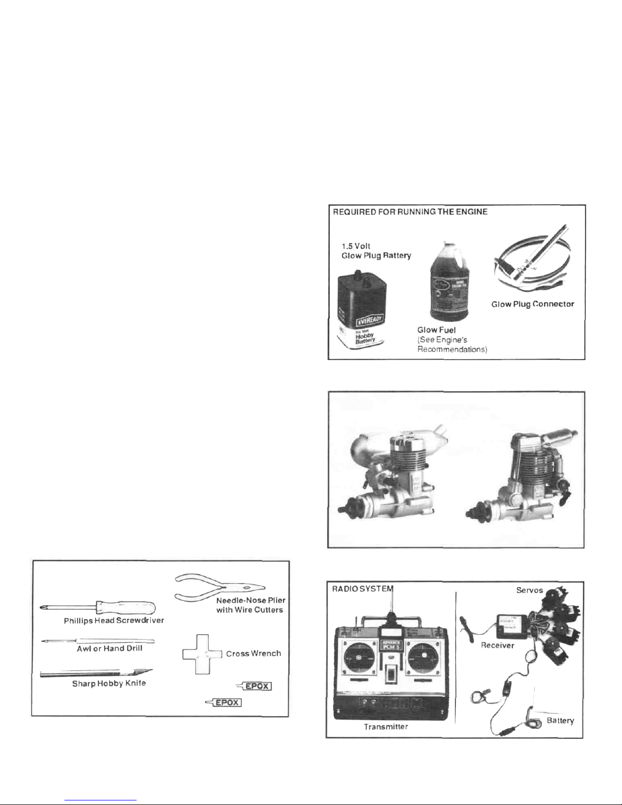
TOOLS REQUIRED
TOOLS-
You will need the following tools to assemble the Extra 300: X-Acto knife,
Philips screwdriver (small and medium), needle nose pliers, drill, drill bits,
sand paper, ruler, and string.
2-
Most engines require a 1.5V glow plug starting battery, a glow plug clip,
and a quality brand fuel (consult the engine manufacturer's
recommendatiions).
A quality brand engine will be needed. We recommend the O.S. .46 SF
2-cycle engine or the O.S. 70 Surpass 4-cycle. A prop and fuel tubing will
be required for the engine.
A four-channel radio control sytem with 4 servos is required for the Extra
300. The various components are pictured above.
Page 3
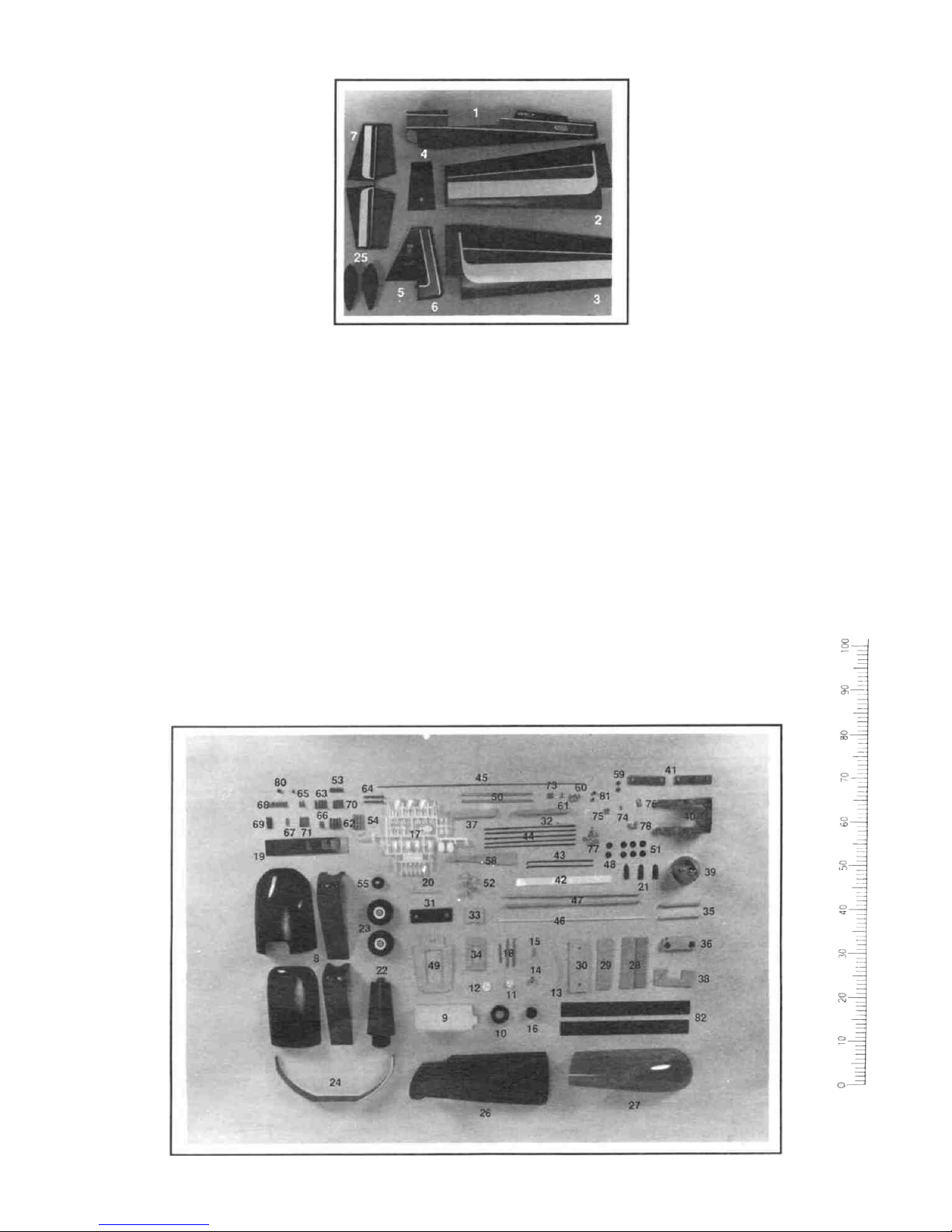
PARTS LIST
Before assembly, match the parts
in the exploded view of the Extra
300 with the parts in the kit. Check
off each part on the parts list. If any
parts are missing or damaged
return the kit to your hobby dealer.
Check to make sure that all the
listed parts are included in your kit.
1 Fuselage
2 Right Wing
3 Left Wing
4 Wing Center Cover (Plastic)
5 Vertical Fin
6 Rudder
7 Horizontal Stabilizer
8 Cowl (4 Piece)
9 Fuel Tank
10 NeopreneRing
11 Plastic Disc (Small)
12 Plastic Disc (Large)
13 Silicone Tubing
14 Clunk
15 3x18mm Self-Tapping Screw
16 Rubber Plug
17 Plastic Collar
Aileron Horn
Control Horns
Snap Clevis
Rod Clevis
Back Plates
18 Fuel Pipe
19 Mounting Plates (Angled)
20 Clevis Retaining Tube
21 Push Rod Exits
22 Stab. Root Cover (Plastic)
23 Wheels
24 Main Gear
25 Wheel Pants
26 Cock Pit
27 Canopy
28 Main Wing Joiners
29 Rear Wing Joiner
30 Front Wing Joiner
31 Rubber Shock Absorber
32 Cowl Brace
33 Aileron Servo Tray Mount
34 Aileron Servo Tray
35 8mm Dowel Rod
36 Wing Bolt Mounting Block
37 Balsa Tank Support
38 Wing Mounting Brace
39 3x12mm Self Tapping Screw
2 1/4" Spinner
Spinner Back Plate
40 Engine Mount
41 Mounting Plates
42 Shrink Tubing
43 Control Rod (Short-Bent)
44 Control Rods
45 Throttle Control Rod (Long)
46 Throttle Tube
47 Wood Push Rods
48 Plastic Disc (Red)
49 Main Servo Tray
50 Stabilizer Supports
51 Plastic Disc (Blue)
52 CockPit Mounts
53 Brass Sleeve
54 Brass Tube
55 Tail Wheel
56 Tail Gear
57 Tail Gear Mount
58 1/8" Wooden Wedge
59 0-Ring
60 Collars
61 Wheel Collar
62 4 x 40mm Screw
63 4 x 30mm Screw
64 2x15mm Screws
65 3 x 8mm Self-Tapping Screw
66 3 x 8mm Screw
67 3x12mm Self-Tapping Screw
68 3 x 5mm Screw
69 3.5 x 15mm Screw
70 3x12mm Screw
71 4x15mm Screw
72 4 x 20mm Screw
73 4mm Nut
74 2mm Nut
75
3mm Nut
76 4mm Washer
77 3mm Washer
78 2mm Washer
79 Lock Washers
80 4mm Washer
81 4mm Nylon Nut
82 Cowl Stripes (Red)
83 Decal Sheet
-3-
Page 4
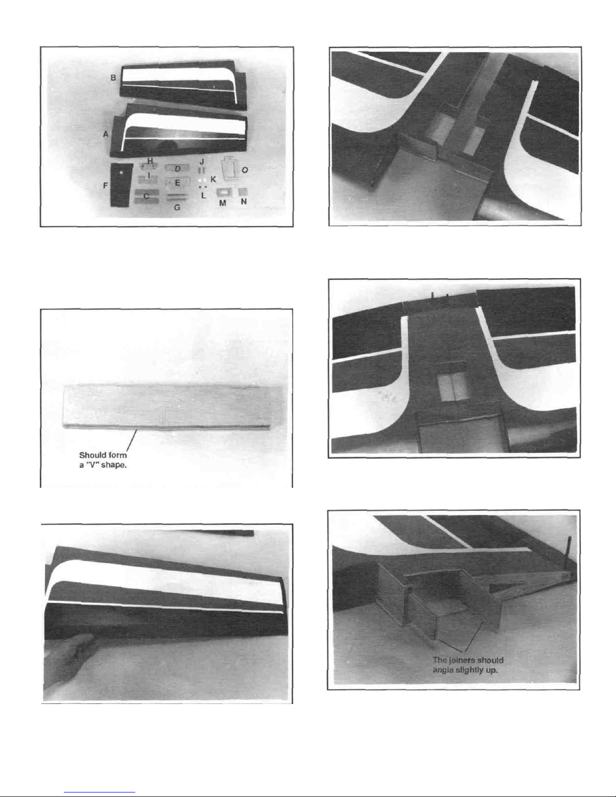
WING ASSEMBLY
A.
Right Wing
(Aileron
Installed) ..........1
B. Left Wing (Aileron Installed)......... 1
C. Main Wing
Joiner.........................
2
D. Rear Wing
Joiner.........................
1
E.
Front Wing
Joiner........................ 1
F Wing Center Cover (Plastic)........ 1
G. 8mm Dowel Rods
..........................2
H. Wing
Bolt
Mounting
Block.............
1
I. Wing Mounting Brace.................. 1
J. 4 x
30mm
Bolts
...........................2
K. 4mm Washer
...............................2
L
0-Ring
........................................2
M. Aileron Servo Tray
......................1
N. Aileron Servo Tray Mount............ 1
0.
Main
Swvo
Tray..........................
1
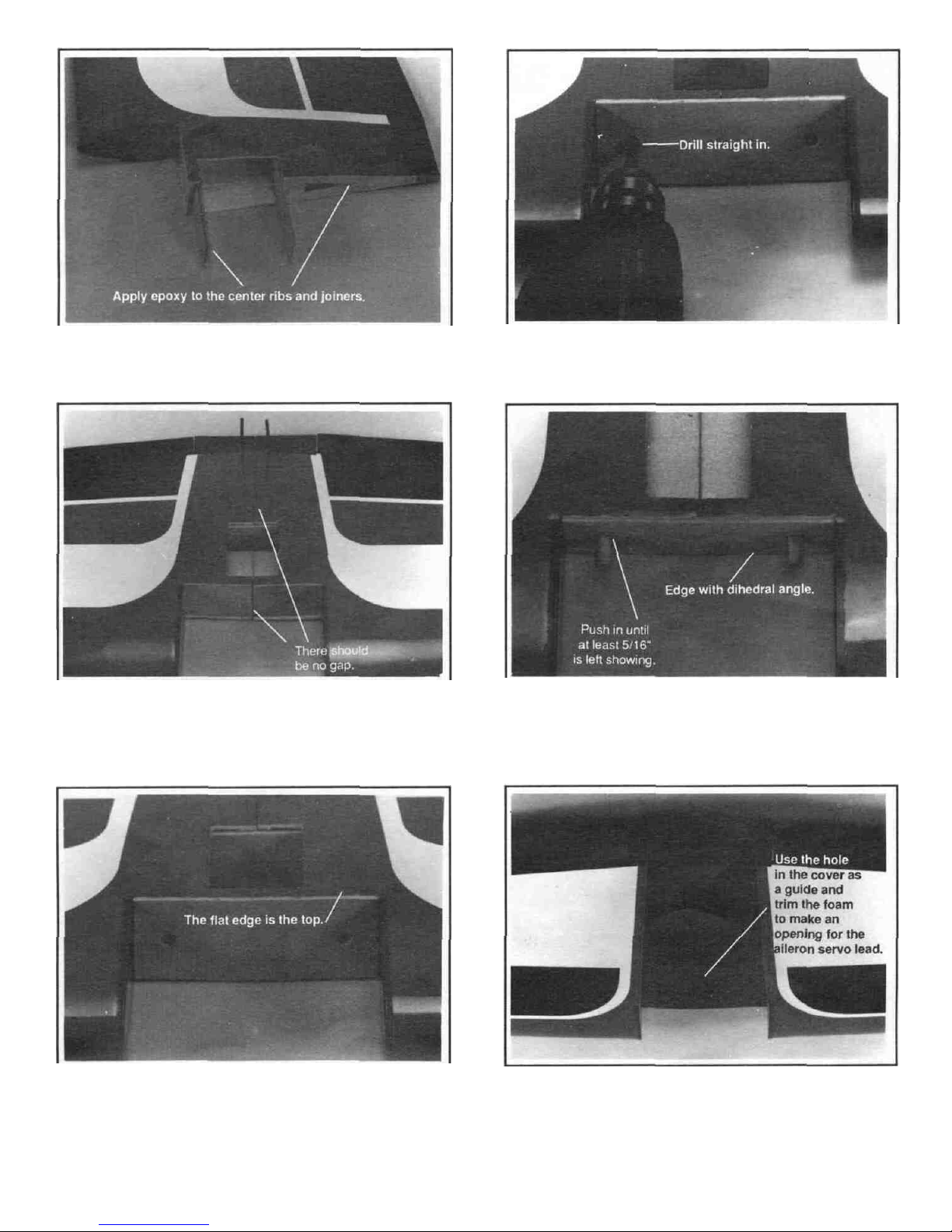
3. Remove the foam covering from the aileron servo mounting area
from the top side of the wing. Test fit the main wing joiner and the
rear wing joiner in the right and
left
wing
sections.
The dihedral angle
of the joiners should make the wing tips slightly higher than the
center.
4. Make sure that there is no gap between the wing halves. If there is,
sand the wing joiner ends until there is a tight fit.
1. Align and epoxy the two main wing joiners together. Hold tight until
the glue sets. You'll notice that there is dihedral angle cut into the
joiners so make sure they are perfectly lined up.
2. Check each wing half for smooth aileron operation. It is a good idea
to exercise (move back and forth) the ailerons to insure easy
deflection. Trim the end of the aileron if any rubbing is noticed.
-4-
5. Apply epoxy to one half of one side of both the main and rear wing
joiners and glue them to one wing half. Make absolutely sure the
wing joiner pocket is well coated with epoxy. Make sure the
dihedral angle is correct and that the wing halves are slid in all the
way. Clean any excess epoxy with paper towel and isopropyi
alcohol.
Page 5
6. After the joiners have cured, apply epoxy where shown. The wing
roots, the wing joiners should be evenly and liberally covered with
epoxy. The wing joiner pocket should be heavily coated with epoxy.
9. Drill two 8mm (5/16") holes into the wing joiners for the dowel
rods. Drill through the front joiner and into the rear wing joiner.
7. Slide the two wing halves together slowly and wipe off any excess
glue. With the wing on a flat surface, hold one wing half down so the
other end will be elevated. The wing tip should be 1 1/16" off of
the surface. Hold the two wing halves firmly together with tape until
the epoxy has cured.
10. Epoxy the two dowel rods into the holes. Make sure they pass all the
way through the front joiner plate and are inserted into the rear
joiner.
8. Once cured, remove the tape. Position the front joiner as shown.
The flat edge of the joiner should line up with the top of the wing.
Next, remove and epoxy in that same position. Let cure. NOTE: You
may have to trim the covering for a tight wood to wood joint. This is
very important to the structural integrity of the wing.
11. Position the wing center cover on the bottom of the wing. Apply
Cyanoacrylate glue (PlastiZap) under the edges and hold until it
sets.
-5-
Page 6
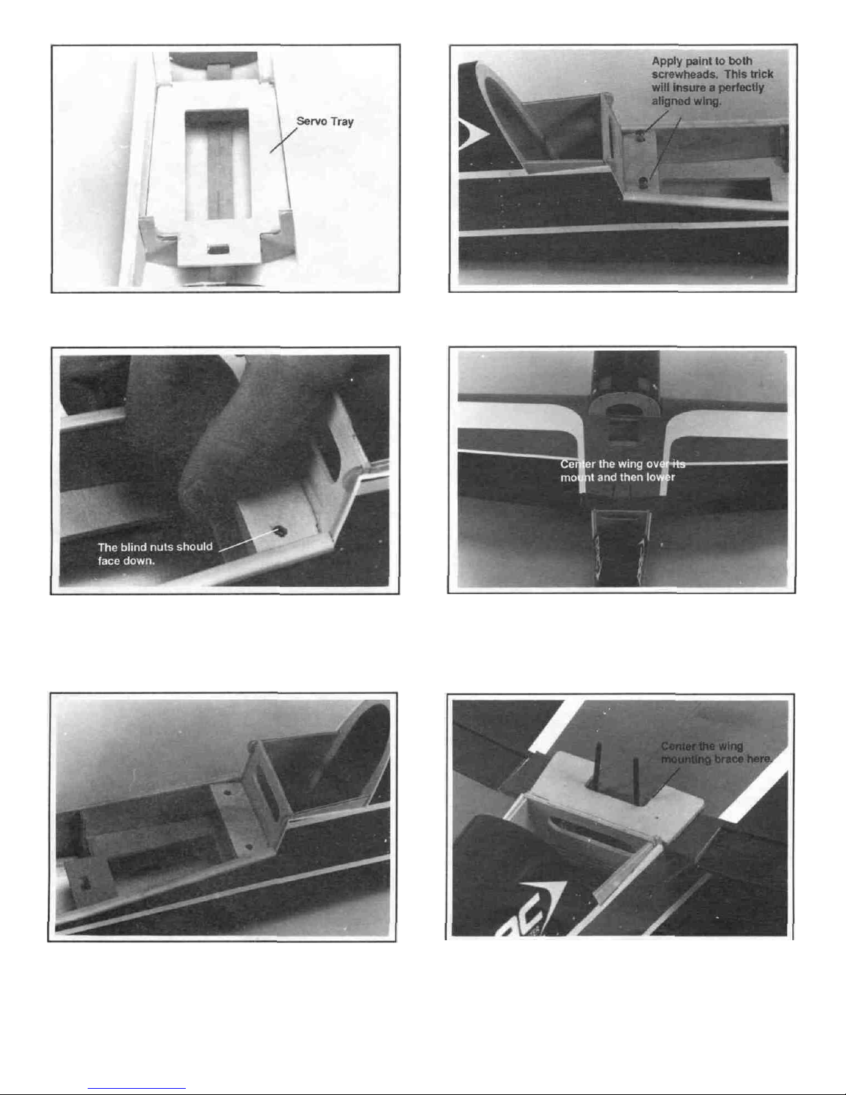
12. Epoxy in the main servo tray as shown.
15. Screw in the wing bolts into the wing bolt mounting block so that the
heads are 1/4" above the block. Apply ink or paint to the heads of
the two bolts.
13. Test fit the wing bolt mounting block to the inside of the fuselage. The
blind nuts should face down. Make sure that the blind nuts are
securly pressed in and then place a drop or two of Cyanoacrylate to
hold them in. Make sure that no glue gets on the threads
16. After the epoxy has cured, place the wing into the fuselage as shown.
Put the front in first by inserting the dowel rods in the holes. Once
in place lower the back into position. This will mark where you need
to
drill.
14.
Epoxy in the wing bolt mounting block. This is a high stress point and
extra care should be taken to ensure a strong joint. Let cure.
17. Place the wing mounting brace onto the wing as shown and center
the wing and brace in the fuselage. NOTE: The two indentations on
the brace should face up. Trim away any wood to allow the aileron
torque rods to move freely. Use PlastiZap to glue this in place.
-6-
Page 7
LANDING GEAR INSTALLATION
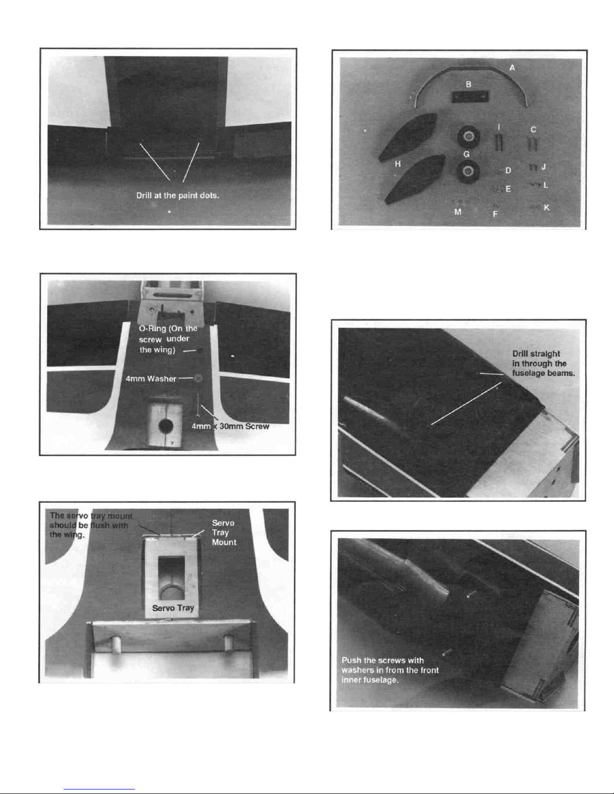
18. Drill two 4mm holes 90' from the top wing surface for the wing bolts
where the paint marks are.
19. Assemble the wing bolts as shown (Bolt - Washer - Wing - 0-ring)
and temporarily fasten down the wing. Check for a good fit and
then remove.
20. Trial fit the aileron servo tray mount and tray to the wing. NOTE: The
front edge should be on the wood. You will have to trim away a little
covering to insure a good fit. You may also have to trim the bottom
of the servo tray mount so it will fit flush inside the wing. Epoxy the
aileron servo tray mount into the rear section of the wing servo mount
and then epoxy in the tray.
A. MainGear.................................. 1 H Wheel Pants...............................2
B.
Rubber
Shock
Absorber..............
1 I. 4mm x 40mm Screw
...................2
C 4mm x 30mm Screw
....................2
J.
3mm x 12mm Screw
...................2
D. 4mm Washer.............................4 K.
3mm Washer.............................2
E. 4mm
Nut...
.................................6
L
3mm
Nut.
................................2
F. 4mm
Nylon
Nut............................ 2 M.
Plastic
Spacer................................
2
G.
Wheel............................................ 2
1. Drill two 4mm holes at the indents.
2. Remove the wing. Place the two 4mm x 30mm screws with the
4mm washers into the two landing gear holes that are located inside
the front fuselage section.
Page 8
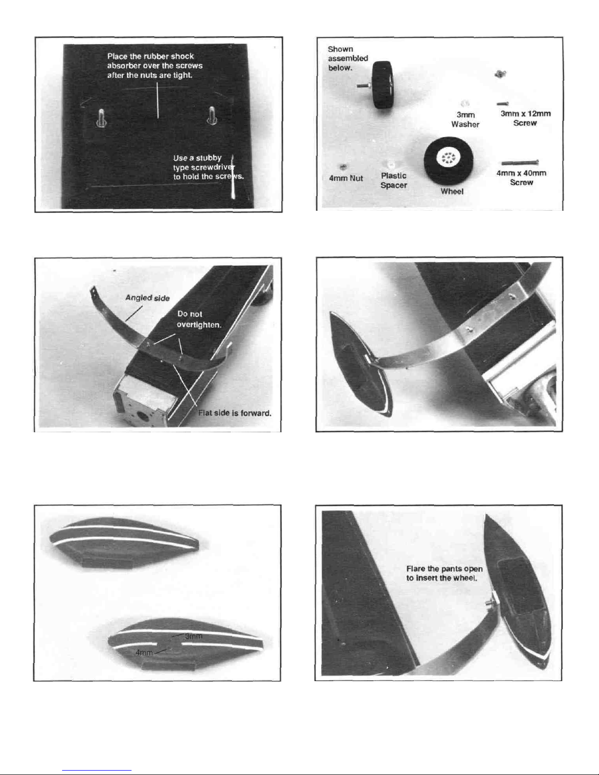
3. Thread two 4mm nuts onto the two screws and tighten Next place
the rubber shock absorber over the screws.
6. Arrange the above parts as shown and then assemble together. Do
this
twice. Place
thread lock on the
threads when
installing
the
nuts
4. Now place the main gear over the screws and secure it with two 4mm
nylon nuts NOTE: tighten
both one turn. This will give the gear the correct shock absorbing
qualities.
5. Next, take the two wheel pants and drill two holes in each one The
first hole should be at the indent (4mm in diameter) The second
should be 3/8" above the first and smaller (3mm diameter) Apply
the wheel pant's decal stripes to both sides of the two wheel pants.
the nuts
all
the way and then loosen them
7. Place the 3mm screw/washer into the top hole of the wheel pants
from the inside And then attach it to the top hole of the main gear
using a 3mm nut with threadlock.
8. Flare open the pants and insert the wheel assembly Install the 4mm
nut with threadlock and tighten, holding the inside nut with needle
nose pliers.
-8-
Page 9
9. Make sure that both wheels rotate freely. If they do not, trim away
the plastic as needed. Or if need be, loosen the nuts and reposition
the wheel.
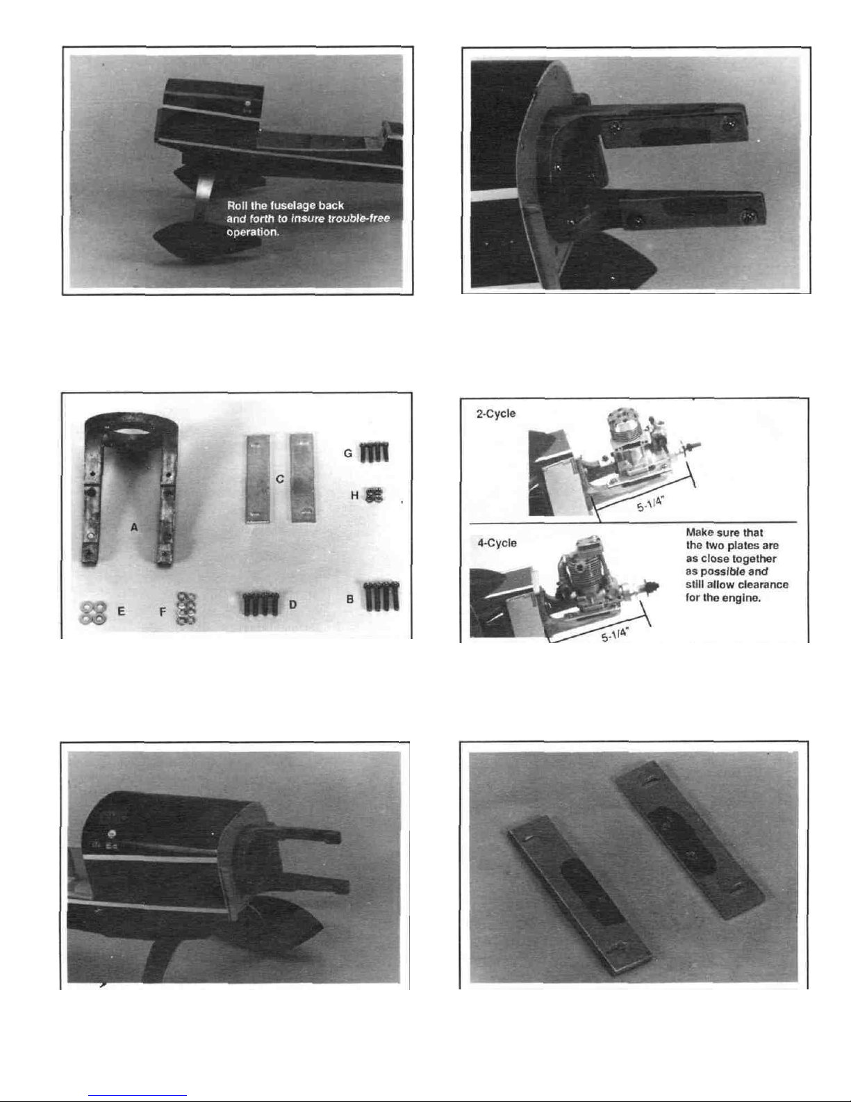
2. Install the two mounting plates onto the engine mount. Next, paint
a strip on each plate using four 4mm x 15mm screws and washers
and proceed with the following step before the paint dries.
ENGINE INSTALLATION
FOLLOW THE SAME PROCEDURE FOR EITHER 2-CYCLE OR 4CYCLE INSTALLATION.
A.
Engine
Mount..............................................................................
1
B. 4mm x 20mm
Screws
.................................................................4
C.
Mounting
Plates
..........................................................................
2
D. 4mm x 15mm Screws
.................................................................4
E.
4mm
Washers.............................................................................
4
F.
Lock Washers
.............................................................................8
G.
3.5mm Screw
..............................................................................4
H. 3.5mm
Nuts
................................................................................4
3. Before touching the plates, align the engine so it is pointing straight
forward. Center the engine with the plates and carefully touch the
engine into position. Now carefully remove the engine and there
will be the guides for drilling the mounting holes.
1. Install the engine mount to the fuselage using four 4mm x 20mm
screws and four lock washers. Note the direction the mount is
installed for proper engine positioning. Also use threadlock on the
screw threads.
-9-
4. Drill two 4mm holes in each mounting plate at the marks.
Page 10

5. Mount the plates to the engine using the 3.5mm screws up from the
bottom as shown. Next apply screw locking compound to the screw
threads and
tighten
on the 3.5mm nuts
with
lock washers.
Do
this
to both sides.
6. When mounting a four cycle engine, the existing throttle control
rod hole (for 2-cycle engines) will not work. Position the engine to the
mount and drill a 1/8" hole into the firewall so it will line up with the
throttle arm on the engine.
7. Now mount the engine to the fuselage. Use four 4mm x 15mm
screws with the four4mm washers. Be sure to use threadlock on the
screws.
ENGINE INSTALLATION
A.
Fuel
Tank................................................................................... 1
B. Clunk
..........................................................................................1
C.
Silicone
Tubing
....................................................................
..
...1
D.
Fuel
Pipe...........................................................
(2)
Long
(1)
Short
E. Plastic Disc(Large).....................................................................1
F. Plastic Disc(Small ......................................................................1
G. 3mm x 18mm Self-Tapping Screw ..............................................1
H. Rubber Plug ................ ......................................................... ....1
I. Neoprene Ring............................................................................1
J. Balsa Tank Support .................................................................... 1
1. Install one of the long and one of the short fuel pipes through the
rubber plug. Center the pipes in the cap. Place the two plastic discs
onto each side. The large one should be on the outside. The bump
on the small one should face the rubber cap Put the 3mm x 18mm
self-tapping screw in the center hole from the large end and tighten
it only a couple of turns into the small disc
10-
2. Attach the silicone tubing to the short fuel pipe and attach the clunk
to the other end
Page 11

3. Carefully bend up the other fuel pipe so it will just touch the inside
top of the fuel tank.
6. Put a bead of silicone sealer on the neoprene ring.
4. Attach the complete fuel tank cap to the tank. Make sure that the
bent pipe is pointing to the top. Slide the cap on until the lip on the
fuel tank is in the groove of the cap. Then tighten the screw. Check
to make sure the clunk is free to swing at the bottom of the tank. This
is where the term "clunk" comes from.
7. Install the fuel tank from the inside of the fuselage with the fuel lines
facing front. Slide the tank into its mount and up into the hole in the
front of the fuselage. Make sure that the fuel tubing is through the
hole.
5. Glue the neoprene ring to the tank with silicone sealer. Attach two
pieces of fuel tubing (6" each) to the pipes. One is for the carburetor
the other is for the pressure tap on the muffler.
8. Epoxy the tank support to the inside of the front fuselage. Once
dry apply a bead of silicone sealer where the support and the
tank touch.
-11
-
Page 12

RADIO INSTALLATION
A.
Aileron
Horn.................................
2
B.
Wood
Push
Rods.........................
2
C. Control
Rods................................
5
D. Control Rod (Short-Bent)............. 2
E.
ShrinkTubing.............................. 1
F. Throttle Control Rod (Long)......... 1
G. SnapClevis................................. 2
H.
Push
Rod Exits
...........................3
i.
Clevis Retaining Tubing
..............1
J.
Throttle
Tube...............................
1
3. Screw two snap clevises half way up the threads on the aileron
control rods. Next, cut two pieces of the clevis retaining tubing
(3/16") and slide them onto the rods.
1. Check the fit of your aileron servo in the aileron servo tray. You may
have to trim away some of the servo tray for a good fit. Install the
rubber grommets onto the servo case flange. Route the servo lead
through the hole in the bottom of the wing and fasten it to the aileron
servo mount using the screws provided with the radio system.
4. Attach the clevises to the aileron horns and slide on the retaining
tubes. After checking the neutral position of the aileron servo and
ailerons, put a mark on the push rods where the servo arm holes line
up. Be sure the aileron is in the neutral position.
2.
Screw the aileron horns onto the aileron control arms. Trim the wing
mounting brace as needed for full aileron movement. Make sure you
use the two horns with the larger holes.
5. At the mark, bend each push rod at a right angle. Next, cut the push
rods 6mm from the bend.
12-
Page 13

RADIO INSTALLATION
6. Locate two rod clevises from the plastic parts tree.
9. Trial fit the servos into the fuselage servo tray, and trim the tray as
needed for a good fit.
7. Attach the rods to the servo arm using the rod clevis. NOTE: You
may have to use a different style servo horn for more throw as shown.
10. Install the three remaining servos (1/4" apart) into the tray using
grommet eyelets and screws. Be sure that the servos are
positioned correctly. Next, mount the radio switch. NOTE: Make
sure
that the
servo wires
all run
forward so they are easily
accessible.
8. Connect the aileron servo to the receiver and check the movement
of the ailerons. Make sure that both ailerons are neutral when the
servo is neutral. Adjust the clevises as needed.
11. We suggest installing an external switch mount so that the radio
system can easily be turned on and off from the outside without
taking the wing off. (The Dubro #203 Kwik-Switch Mount works
well.)
-13-
Page 14

12. Assemble the rudder and elevator control rods using the parts
above.
15. Cut four equal pieces of the white shrink tubing (about 2" each)
13. Bend two of the long rods as shown for the elevator and one of the
rods for the rudder.
16. Assemble the elevator push rod as shown. Place the two elevator
rods into the double grooved end of one of the rods. Next, place one
of the short (pre-bent) rods into the other end.
14. Drill a 1/16" hole 2" from the ends (2 holes 1/16" apart on one end
of one rod) of both wood push rods. With a hobby knife, carefully
cut straight grooves from the holes to the ends. Only cut a groove
on one side of each end. except for one end of one rod (the one with
two holes). For this one end, make a groove on both sides.
17. Next, do the same with the other rudder rod. Make sure that each
rod fits in a groove. Now slide the four pieces of shrink tubing over
the ends of the wooden rods and shrink them with a heat gun or
lighter. To ensure durability, place a drop or two of Cyanoacrylate
glue to the edges.
-14
Page 15

18. Punch out the three rod exits at the tail and insert the rudder pu sh rod
into the fuselage from the front and then through the bottom exit on
the right side. Do the same with the elevator rod, but put those
through the top two holes. It may be necessary to bend the rods
slightly to fit.
21. Use the throttle control rod and the white throttle tube for the engine
linkage. Lightly sand the plastic tube so the epoxy will adhere to it.
Cut the plastic tube so it is only 12" long.
19 Using PlasiZap, glue the three plastic push rod exits to the
fuselage.
22. Install the plastic tubing through the hole in the firewall to the servo
tray Epoxy the tube where it goes in If using a four cycle engine,
install the tube into the drilled hole from Page 10.
20 Check to make sure that the rods will easily move in and out with little
resistance. You may have to bend the rods slightly for a perfect fit
(we will connect the rods to the servos after the tail assembly).
23. Make a "Z" bend on one end of the throttle control rod and insert the
opposite end into the tube.
-15-
Page 16

24. Connect the servos to the receiver and battery and center all radio
controls (including the throttle stick and move the servo horns so
they are in line with the servo as shown. After they are centered, pull
the throttle stick back down (low throttle). Install the straight servo
horns that are included with your radio system.
27. From the inside, pull back the throttle control rod so the carburetor
is closed. Now, mark the rod where it crosses the throttle servo horn
(in low posistion).
25. Connect the "Z" bend to the engine throttle arm. It may be necessary
to remove the arm from the engine for easier installation.
28. Next, at the marked point, make another "Z" bend, cutoff the excess
and attach it to the servo arm. For easy adjustments, an easy
connect can be used here. (Dubro#121 E-Z Connectors work well.)
26. Epoxy the white tube to the tube guide.
29. Check for proper radio operation of the throttle. Make sure that the
carburetor will move from low to high completely.
-16-
Page 17

NOTE: The tail wheel parts M-T may vary due to an updated design.
See page 18, Step 10.
A.
Horizontal
Stabilizer..................... 1
L Tail Wheel................................... 1
M. Tail Gear..................................... 1
N. MetalStrip...................................1
0.
3mmx12mmSelf-TappingScrew 2
P.
3mm x 5mm
Screw
.....................
1
Q. Wheel Collar
...............................1
R.
BrassCollar
................................1
B. Vertical
Fin...................................
1
C.
Rudder......................................... 1
D. 1/8-Wooden Wedge.................... 1
E.
Stab. Root Cover (Plastic)
...........
1
F. Stab. Supports.............................2
G. Plastic Disc
..................................4
H.
BrassSleeve
...............................2
I.
2mm x 15mm Screw
....................2
J.
2mm Nut...................................... 2
K.
2mm
Washer
...............................4
3. Install the main wing. Next place the horizontal stabilizer onto the
tail. Hold it on and visually see if the wing and stabilizer are parallel.
If not, sand the higher side of the stabilizer mount until! the stabilizer
is parallel.
4. Next take a piece of string and attach it with a pin to the top center
of the fuselage. Make sure that the stabilizer is centered and stretch
the string to the corner of the elevator. Adjust the positioning of the
stabilizer so that both corners are the same length when moving the
string from side to side.
1. Test fit the 1/8" wooden wedge into the tail end of the fuselage. If
there is a good fit, epoxy it in place making sure that it is even with
the fuselage sides. NOTE: It may be necessary to trim away some
wood or glue to make the wedge fit flush.
5. Next, remove the stabilizer and apply epoxy to the wedge. Reinstall
the stabilizer and re-center like before.
-17-
2. Trim away as necessary part of the plastic rear cover to allow
proper fit of the horizontal stabilizer.
Page 18

6.
Once the horizontal
stabilizer epoxy has cured,
trial
fit the
vertical fin
(without the rudder)
on
top
of
the horizontal
stabilizer
and
the
back
edge is even with the rear of the fuselage. Draw a line on both sides
of the fin as shown
9. When satisfied with the fairing positioning, apply cyanoacrylate glue
to the underside edge of the stabilizer cover and install in place
7 Next, apply epoxy to the top of the horizontal stabilizer and re
position the fin between the lines Make sure that the fin is still 90"
to the stabilizer Do the next step before the glue sets
10. Assemble the tail wheel section shown Slide on a brass collar,
the tail wheel, and install the wheel collar with a 3x5mm screw.
8. While the epoxy is still wet, position the plastic stabilizer fairing cover
over the fin Double check the positioning of the fin after doing this.
Allow epoxy to set.
11 Inserta 3mmx12mm self tapping screw through the middle hole of
the metal strip and attach to the under side of the tail section so
that the screw is positioned 1/2" from the end of the fuselage.
-18-
Page 19

12. Now take the supports and bend the ends as shown above.
15. Install the tail wheel
assembly
through the
metal
strip.
Next,
trail
fit
the rudder onto the vertical fin. Notice where the bottom hinge
meets the fuselage and make a slot in the tail where the rudder hinge
needs to be with an X-Acto knife.
13. Attach the two supports onto the fuselage with a 3mm x 12mm selftapping screw. Make sure that the metal strip is straight.
16. Next, drill a 2mm hole about 1" deep at 7/8" from the bottom of the
rudder. The hole should be straight in from the front edge.
14.
Position
the
supports straightout (90')
to
the
fuselage.
Mark where
the supports touch the horizontal stabilizer, drill a 2mm hole on each
side at the marks. Next, cut 1/8" off of two brass sleeves. Finally,
attach the supports as shown in the drawing above.
17. Notch a small groove (1/8" deep) from the hole down to the bottom
for the tail control arm.
-19-
Page 20

18. Place a small amount of epoxy on the hinges, in the groove, and on
the end of the tail control arm. (It is a good idea to place some
petroleum jelly onto the hinge center joint (point of movement) to
keep out any epoxy.
1. Glue (using PlastiZap) the rectangular mounting plates to the rudder
so that they are centered, one on each side, over the tail control arm
that is "inside" the rudder.
19. Carefully postion the tail control rod into the hole and the groove.
Wipe off any excess epoxy and then insert the hinges into the slots.
Wipe off any excess epoxy from the hinges and check for free
operation. Let cure.
2. Using PlastiZap again, glue the angled mounting plates, one on
each side, on the two elevator halves as shown.
ELEVATOR/RUDDER CONTROL ROD INSTALLATION
A.
Control
Horns..............................................................................3
B. Back
Plates....................................................................................3
C. Mounting Plates (Rectangled)
.....................................................2
D. Mounting Plates
(Angled)
............................................................4
E. Brass
Tubes................................................................................6
F. 2mm x 20mm Screws
.................................................................6
G. Clevis Retainer Tube
..................................................................
1
H. Rod Clevis
..................................................................................2
I.
Snap
Clevis.................................................................................
3
3. Using the control horn as a guide, center and mark two holes for
drilling on all three mounting plates. The horns will then be
mounted - two underneath the elevator and one on the right side
of the rudder (as viewed from the rear).
-20-
Page 21

4 Drill six 3mm holes for the three horns Make sure that you drill
straight through to the other side
7 Cut the clevis retaining tube so that you have three 3/16" tubes
8 Slide on one of the retaining tubes onto each rod Screw on the
plastic snap clevises to the three push rods coming out of the
fuselage Screw them on half way up the threads
5 Install the six brass tubes into the holes
6 Mount the control horns to the surfaces with the 2mm x 20mm
screws Pass the screws through the horn, through the tubes and
finally thread them into the back plates
9 Attach the respective control rods to each horn Use the middle hole
of the horn Turn on the radio system and adjust the clevises for
centered control surfaces Slide up the retaining tubes to lock the
clevises.
-21
-
Page 22

10 Align the rods over the servo horns and make a mark where they
intersect Make sure that the control surfaces are in neutral (center
position) before marking.
11. Next, make a 90' bend upwards at the mark and cut-off the excess
so that there is only 6mm of rod after the bend.
COWL AND PROP INSTALLATION
A.
Cowl
(4
piece)...
.........................................................................
1
B.
Cowl Brace
..............................................................................1
C.
3mm x 10mm
Self-Tapping
Screw
..............................................3
D.
Spinner
.......................................................................................1
E.
Spinner
Back Plate
.................
................................................
1
F.
3mm x 12mm
Self-Tapping Screw
..............................................2
G.
Mounting
Block . .................................................................
1
H. White Striping Tape
1/4"
.............................................................
1
12 Attach the rods to the servos using the rod clevises as shown in the
above drawing You may need to enlarge the holes in the horns
slightly for a good fit.
1. Epoxy the small mounting brace to the top of the firewall Fill any
gap with epoxy, allow to cure.
2. Trim away some of the plastic from under the front of the fuselage
where shown.
-22-
Page 23

3. Epoxy the cowl brace onto the front of the fuselage. Make sure that
the beveled ends angle down in line with the fuselage. Attach the
muffler to the engine if using a two cycle. Remove, if necessary,
the muffler/pipe if using a four cycle engine.
6. Apply the 1/4" white striping tape to the seams on the outside of the
cowl.
4.
Lightly sand the flanges on the upper and
lower
cowl edges.
This
will
allow the glue to adhere better to the plastic. Next, hold or tape the
left side over the flange of the lower cowl and glue together along the
inside seam with CA glue. Finally, install the right side in the same
manner and glue.
7. Trail fit and trim the cowl as needed so that the engine muffler
will exit with at least 1/8 - 3/16" clearance. Now, carefully cut two
holes in the cowl, one hole on the side to the cylinder head. Now
cut one where the needle valve is located for easy accessibility.
For four cycle engines, cut another hole for the choke linkage.
5. Trail fit the upper cowl in place from the inside. Check for a good fit.
You
may
have to trim the upper cowl flanges slightly
for
a perfect
fit.
Once satisfied, place a light bead of CA glue along the length of the
flange and hold in place until the glue cures.
8. Slide the cowl onto the fuselage and make 3 marks (1 on top, and
1 on each side) where the mounting block and cowl brace
are located.
-23-
Page 24

9. Reposition the cowl and drill a 2mm hole at each point and attach the
cowl using three 3mm x 8mm self-tapping screws. If using a 4-Cycle
engine, install the muffler/pipe at this time.
2. Install the battery first into the front of the fuselage as shown and
then install the receiver on top.
10. Install in order (spinner backplate - prop - prop washer - prop nut spinner cone - two 3mm x 12mm self tapping screws) onto the
engine crankshaft.
3.
Drill
a small
1/16" hole into the left side
of
the fuselage under the
wing and drill a hole at the top of the vertical fin.
RECEIVER AND BATTERY INSTALLATION
1. Hook up the servos and wrap the receiver and battery in natural foam
rubber to protect it from vibration (Goldberg #481 Foam Rubber
1/4" works well). Use the aileron extension for your particular radio
installation.
4. Make a small knot 6" from the receiver and route the antenna wire
out through this hole and up through the hole in the tail.
.24-
Page 25

5. Use the antenna retainer and secure the wire to the tail.
2. Once the epoxy has completely cured, position the cockpit on the
fuselage. Make 4 small
holes where
the cockpit
mounts
are
located.
Attach with the 4 small self-tapping screws. Do not glue the cockpit.
Apply the instrument decal to the front of the cockpit.
COCKPIT/CANOPYASSEMBLY
A.
Cockpit....................................................................................... 1
B. Canopy....................................................................................... 1
C. Cockpit Mounts
..........................................................................4
D. 3 x 8mm
Self-Tapping Screws
....................................................4
E. Decals........................................................................................2
F. Striping Tape
..............................................................................1
3. Trial fit the canopy to the cockpit. If necessary, trim for a perfect fit.
Apply a
thin
bead
of
Cyanoacrylate
glue
to
the cockpit and attach and
hold the canopy until secure. Now apply the black striping tape to
the edge of the seam.
1. Connect the aileron servo lead to the receiver and install the wing.
Epoxy the four cockpit mounts to the fuselage as shown. Be careful
when gluing the rear mounts to only glue them to the wing mounting
brace.
4. Apply the red sthpes to the side of the cockpit and trim as shown.
Apply the "Extra 300" decals to the cowl sides.
-25-
Page 26

SERVO THROWS CENTER OF GRAVITY
The amount of throw that the control surfaces have is critical if you want
a properly responsive plane Measure the throws as shown above They
should be.
Each way
3/16"
9/16"
13/8"
Ailerons
Elevator
Rudder
Total
3/8"
1
1/8"
23/4"
If not, move the clevis to a different hole or use a larger servo horn.
TRANSPORTING CHECKLIST
Balance the plane using the mark on the side of the fuselage. It should
balance at this point See below.
The center of gravity is a very important aspect of setting up the airplane
properly It will control a large part of what type of flying characteristics
your plane will have, if it is nose heavy the airplane will try to dive, and the
elevator will be sluggish to respond to your control inputs If the plane is
tail heavy the airplane will be very sensitive to the elevator and possibly
uncontrollable The center of gravity should be checked with the fuel tank
empty in the plane to be accurate The range in which the airplane should
balance is marked with a black dot on the side of the fuselage With
standard radio equipment, the plane should balance within this range If
it does not balance within this range, feel free to add weight to the nose
or tail as you need to obtain proper C G.
Before leaving for the flying field go through the checklist. This will
help prevent you from forgetting to take things with you.
1. Make sure radio batteries are all charged.
2. Make sure the transmitter and receiver are on the same
frequency
3. Glow plug clip and fully charged 1 1/2 volt battery.
4. Fuel and fuel pump or fuel bulb
5. Extra props and prop wrench
6 Screw drivers, knife, pliers, and wrenches.
7 Epoxy and something to mix it on.
8. Paper towels
9. Cleaner to remove residue on the plane.
10. Extra glow plugs
11. Electric starter or chicken stick.
RADIO CHECK
Always check the operation of your radio before you fly to see that the
control surfaces move in the proper directions and that they move the
proper amount If the direction of rotation needs to be reversed to
correct for reversed controls, simply change the side of the servo arm
to
which the push rod is
attached
or
flip the proper servo reversing
switch on your transmitter To INCREASE the amount of movement
that the surface will have, move the CLEVIS CLOSER to the surface
or move the (ROD CLEVIS OR E Z CONNECTOR) away from the
center of the servo arm To DECREASE the amount of movement,
move the CLEVIS AWAY from the surface or move the (ROD CLEVIS
OR E Z CONNECTOR) closer to the center of the servo arm
IMPORTANT SAFETY MEASURES
Receiver Battery
1. Always make sure the receiver battery pack is fully charged before
flying
2. Wrap the receiver battery in 1/2" soft foam rubber to protect it
from engine vibration and shock A rubber band may be used to
hold the foam around the battery pack It is also suggested
to place the battery pack in a plastic bag to protect it from fuel
3. If using NiCd batteries, follow the instruction that came with your
radio for charging and care of the batteries
4. Before the first flight of the day, check all the wires on the battery
pack and switch for corrosion or broken wires
5. Do a pre-flight check of your radio system each flying
session
Receiver
1. Do not cut the receiver antenna. This may affect the sensitivity
of the receiver
2. Carefully wrap the receiver in foam and a plastic bag like the
receiver battery
3. Make sure that all the servos are plugged into the correct receiver
terminal
Servos
1. Make sure that all the control surfaces move smoothly without
binding When installing the push rods the servo must be able to
move through its complete range of rotation
2. If the servo buzzes when the transmitter stick is moved to its
limit, the servo still has some movement left This can damage
the servo and drain the battery which may cause loss of control
of the plane and crash
-26-
Page 27

STARTING ENGINE
Engine Maintenance
Always check
the engine mounting bolts,
muffler, glow
plug,
propeller
and
spinner, etc .before attempting to start the engine Check for loose bolts,
nuts or screws which may come off when the engine is running and cause
serious damage Always check the area in which you will be flying or just
running the engine Check for possible hazards, such as loose rags,
rocks, tools, etc , lying on the ground which may get caught in the prop
If you intend on starting the engine by hand flipping the prop, always use
a chicken stick, and be sure to check the position of the prop It is most
comfortable when it is at the 2 o clock position when starting the
compression stroke When you are using an electnc12V starter, try to
position the prop parallel to the wing
Engine Break-In and Starting
Most manufacturers recommend that the engine be broken in on a test
stand We also recommend that this be done according to manufacturer's
instructions If a test stand is unavailable the engine may be broken in on
the airplane Breaking in the engine allows the parts to "seat" to each
other
1 Use a filter on the caburetor line
2 Remove the carburetor fuel line and the muffler pressure line from
the muffler
3 Fill the fuel tank through the carburetor fuel line, when the tank is full
the fuel will come out the pressure line
4
Reconnect the
tubing
5 Follow your manufacturer's instructions according to needle valve
settings
6. Turn the radio on and open the throttle to full open Place your finger
over the air intake on the carburetor while turning the prop counter
clockwise a few times Notice the fuel line If no fuel is reaching the
carburetor, recheck the fuel line plumbing
7 Reduce the throttle to 1/4 or 1/2 throttle for starting
8 Using a starting stick (chicken stick) and holding the fuselage firmly
quickly flip the prop in the counter clockwise direction Do not attach
the glow
plug
clip
in
this
step
This
will
prevent the
engine
from
being
flooded and will make starting much easier Do not use bare hands/
fingers for starting, as the kick back from a model engine can be
strong enough to cause severe injury
9 Attach the glow plug clip at this time
10 With quick flipping movements, flip the prop in the counter-clockwise
direction
If
the
engine
does
not try to start in the
first
few
tries, double
check your procedure and keep trying
11. Once the engine has started, listen carefully to the sound of the
engine The sound of the engine will tell you how the engine is
running, if you know what to listen for A lower tone, popping sound
is the sound of a rich running engine As you turn the needle valve
in, the popping sounds should decrease and the pitch of the engine
should rise The optimum needle valve setting will depend on your
engine and current weather conditions Again check with the
manufacturers recommendations for engine break in procedures
and valve settings
12 If you continue to have problems with the performance or starting of
your engine, refer to engine trouble shooting guide as shown below
ENGINE TROUBLESHOOTING GUIDE
SYMPTOM
The engine does not start.
The propeller is difficult to
rotate
The engine fires but does
not start.
The engine starts but does
not sound or run good
POSSIBLE CAUSE
Glow plug battery is making poor contact.
Battery is dead or has a very low voltage
Bad glow plug (burned out or deteriorated
filament)
Improper air/fuel mixture intake
Engine is flooded with fuel.
Engine may be flooded.
Fuel is not reaching the carburetor.
Improper break in procedures
Loose plug or bad plug
SOLUTION
Check to see if the battery is wired correctly and to
see if the clip is making good contact with the plug
Replace or recharge the battery and check to make
sure the battery can glow the plug red hot pnor to
starting
Replace the glow plug
Prime the engine through the carburetor air intake
Close the needle valve completely and try to start
the engine It should start and then quickly stop
Reset the needle valve and continue starting
Remove the glow plug and rotate the engine until
only a mist of fuel remains in the cylinder Replace
the plug and continue
Check the level of fuel in the tank Recheck fuel
Open the needle valve a half turn or so and continue
Check the break in procedure and repeat
Replace the plug and/or tighten the old plug
-27-
Page 28

Pre-Flight Check
1. Clean the dust dirt, and oil off of the surface of the airplane
2. Check to make sure all nuts, bolts, and screws are securley
fastened
3. Check all control surfaces to see if they are properly attached.
4. Check the range of the radio system as the manufacturer
recommends
5.
Check that all controls move
smoothly
and
in the proper directions.
6. Check the level of charge in the transmitter and receiver batteries
7. Check that the area being used is free of obstacles and debris
8. Check the frequencies currently in use at the field and in your
area
9. Check the level of the fuel tank to be sure it is full
10. Double check the radio operation
Flight Safety
• If this airplane happens to be your first radio controlled airplane, we
strongly suggest that you ask a skilled pilot or instructor to help you
learn how to fly You should also suggest to him to take the maiden
flight
to
see what
problems
(if
any) that
need
to be worked out There
will be enough to worry about on your first solo flight without having
to worry about whether or not it is properly set up
• Fly in an open field without any obstructions For example, trees,
power lines, buildings, crowds of people, etc , are obstacles that the
plane may hit and cause damage
• If you are a novice pilot, local area clubs have been formed and are
very willing to help you with any questions you may have Many of
the clubs even have club trainer airplanes that they will actually teach
you to fly with This helps prevent disappointing crashes on your first
flights Addresses of local area clubs can be located from your local
area hobby shop and/or by writing to Academy of Model Aviation,
1810 Samuel Morse Drive, Reston, VA 22090
• Fly the model at reduced throttle until you get to know the flight
characteristics
• When adjusting the needle valve JU st prior to flight, hold the plane at
a 45" nose up altitude, full open throttle and adjust the throttle for top
performance as the manufacturer's instructions suggest.
Take-Off
The airplane may be taxied around on a smooth/open section of
pavement without the wing and the engine has been adjusted and the
radio has been properly checked Become familiar with controlling the
plane on the ground with the rudder, in the air you will find that most of the
time you will be using a combination of elevator and ailerons to turn the
plane because they are more effective in the air On the ground, the
rudder is more effective A transition will need to be made once the plane
leaves the ground That transition, from using the rudder on the ground
to using the ailerons once it leaves the ground, will take a little practice
Once good rule of thumb is to always take off directly into the wind (if there
is any) This will prevent the wind from trying to blow the model from sideto side and will not take as much runway as if you were trying to take off
downwind
One you feel comfortable with the way it handles on the ground, it
comes time for you to concentrate very much on the airplane's movements
As you are ready for take off, simply point the nose into the wind and
slowly advance the throttle up to full throttle At this point the plane will be
going very fast and will be very sensitive to your rudder inputs Use
smooth inputs to correct the plane from wandering off of the runway Once
the plane is at take off speed, slowly pull back on the elevator stick This
will cause the plane to leave the ground At this point, notice whether the
plane tends to turn. climb or dive, and make the necessary opposite
control inputs to keep the plane on a gentle climb in the desired direction.
Flight
Once the plane has reached a safe altitude, reduce the throttle to
about half power If the airplane is properly set up (i. e. correct C G .trims
all centered, engine properly set), the plane should be very stablewithout
any wandering tendencies. If the plane does tend to go more in one
direction
than another, use your
trim levers
on
your
transmitter to correct
this Do not look at the transmitter while adjusting trims Then while the
plane is flying straight, adjust the elevator trim to correct abnormal
climbing or diving If the trims will not overcome a turn or a climbing
tendency, land the model immediately and check for improper setup
Landing
There is an old saying that states, "You do not have to take off ..
But you do have to land " Therefore, be ready to land at all times during
your flight The engine may not stay running through a complete tank of
fuel for one reason or another It is suggested to time the "run time" of a
complete tank before flight That way you know approximately what to
expect and when you need to land before the fuel runs out
Set up your landing approach downwind at 100 200 feet up and 500
800 feetaway depending on the height of the plane and the strength of the
wind Approach into the wind and slowly reduce the throttle to the closed
position Concentrate on the glide path of the plane, taking notice of
whether the plane will reach the beginning of the runway or if it will
overshoot the runway completely With smooth, deliberate inputs, use
your engine power and your elevator to adjust the glide path so the plane
will touch down smoothly on the beginning of the runway at its slowest
speed Itwill still seem very fast and will use the complete runway to slow
down.
After-Flight Maintenance
• Remove all excess fuel from the fuel tank as this fuel can become
jelly like and cau se clogging of the fuel lines as well as clogging the
engine's carburetor valves
• Always use after run oil in the engine to prevent corrosion
• Check and double check that the transmitter and receiver switches
are switched to the off positions
• Wipe off the excess oil that will collect on the wing and fuselage
Use
a light duty cleanser to help cut through the oil
• Remove fresh fuel from the surface of the plane immediately as
different brands can cause clouding of the surface
• Replace any bent, marred, or dinged props as they can fly apart at
any time when the engine is turning
• Completely check the alplane for damage to the wings, landing gear,
covering and repair as needed before your next flight.
Repair
If damage should occur, wipe the broken area clean with a clean rag to
remove all debris Use epoxy glue to repair Do not use Cyanoacrylate
adhesive near any foam parts as it will deteriorate the foam
Fully Assembled Extra 300
-28
 Loading...