

Page 1
PLEASE READ THESE OPERATING INSTRUCTIONS CAREFULLY.
Misuse and/or abuse of this instrument may cause injury and/or damage to
the meter or the equipment under measurement. Please read and follow all
instructions carefully. Please inspect the meter and test probes for wear or
abnormalities prior to every use. If a flaw exists, do not attempt to take any
measurements. Replace the damaged equipment. Never touch exposed
wiring, connection, or line circuit conductors when attempting to take
measurements. Damage resulting from a failure to follow instructions will
void the warranty.
HCAZ3064 for HCAP0360© Copyright 1999 Printed in China
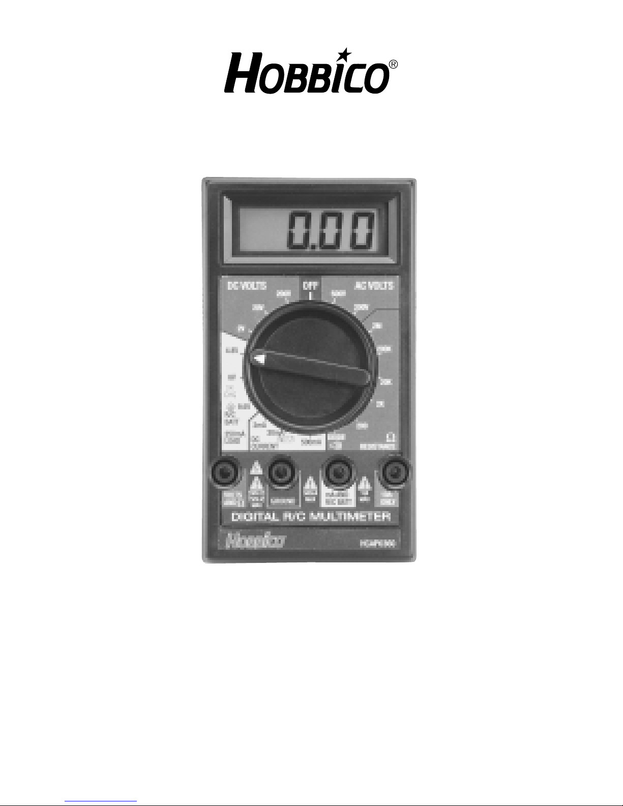
DIGITAL R/C MULTI-METER
OPERATION MANUAL
Page 2

· Pocket-size
· Simple operation
· 300 hour battery life
· Maximum 10A DC current range
· Recessed safety designed input terminals
· Built-in table stand
· Overload protection on all ranges
· Diode test function
· Audible continuity buzzer
· R/C battery test function with 250mA simulated load and
go/no-go LED
· 15 minute auto-off function
Display: 3-½ digit LCD, 0.5" numerals,
maximum reading “1999” with
automatic polarity sign and
weak LCD battery indicators
Overrange Indication: A “1” will blink in the most
significant digit
Sampling Rate: 2.5 times per second
Operating Environment: 32° to 122°F (0° to 50°C) at less
than 70% relative humidity
Storage Environment: -4° to 140°F (-20° to 60°C) at
less than 80% relative humidity
Power Source: One 9V carbon zinc battery
Power Consumption: 30mW typical
Battery Life: 300 hours typical
Sleep Mode: 15 minute auto-off timer
Low Battery Indicator: Battery symbol in LCD window
SPECIFICATIONS
FEATURES
2
Page 3

Max. Common Mode Volts: 500V DC or AC peak voltage
Accuracy Temp. Coefficient: (10°C-18°C and 28°C-50°C)
less than 0.1x applicable
accuracy specification per
degree C
Fuse: 0.8A, 250V, 5 x 20mm fast
acting cylindrical glass
Dimensions: 5.0" x 2.8" x 1.4"
Weight: Approximately 7.0oz. (200g)
including battery
Accuracies are +/- (% of reading + number of digits) at 23°C
(+/-5°C), less than 75% relative humidity.
R/C Battery Check
Range Resolution Red LED Green LED
4.8V 0.01V 2.0 - 4.7V 4.9V or higher
6.0V 0.01V 2.0 - 5.9V 6.1V or higher
9.6V 0.01V 2.0 - 9.5V 9.7V or higher
Overload protection: 0.8A / 250V fuse on mA inputs.
Load current each selection: 250mA
DC Voltage
Range: 2V, 20V, 200V +/- (0.8% of
reading + 1 digit)
Overload protection: 1000V DC or 750Vrms AC for
15 seconds
Impedance: 10M
AC Voltage (50-400Hz)
200V selection: +/- (1.5% of reading + 4 digits)
RANGES
3
Page 4
500V selection: +/- (2.0% of reading + 4 digits)
Overload protection: 1000V DC or 750Vrms AC for
15 seconds
Impedance: 10M
DC Current
Range: 2mA, 20mA, 500mA +/- (1.2%
of reading + 1 digit)
10A selection: +/- (2.0% reading + 3 digits)
Overload protection: 0.8A / 250V fuse, no protection
for 10A selection
Resistance
200 selection: +/- (1.5% reading + 3 digits)
2k , 20k , 200k , 2M : +/- (1.0% of reading + 1 digit)
Overload protection: 400V DC / AC rms
Diode Test
Test current: 1.0mA +/- 0.6mA
Test voltage: 3.2V maximum
Continuity Test
Audible indication: less than 50 approx.
1. Read these operating instructions thoroughly and completely
before operation. Pay close attention to the WARNINGS and
CAUTIONS which will inform of potentially dangerous
procedures.
2. Always inspect your meter, test probes and accessories for
any sign of damage or abnormality before every use. If any
abnormal conditions exist (broken test probes, cracked plugs,
SAFETY RULES
4
Page 5

faulty display, etc.), do not attempt to take any
measurements.
Refer to the Troubleshooting Guide at the rear of this manual
for further information.
3. Never ground yourself when taking electrical measurements.
Do not touch exposed metal pipes, outlets, fixtures, etc.,
which might not be at ground potential. Keep your body
isolated from ground by using dry clothing, rubber shoes,
rubber mats, or any approved insulating material.
4. Never touch exposed wiring, connections or any live circuit
conductors when attempting to take measurements.
5. Never replace the protective fuse inside the meter with a fuse
of a different rating.
6. When testing for voltage, make sure the voltage function is
operating properly by reading a known voltage in that range
before assuming that a zero reading indicates a no-voltage
condition.
7. Calibration and repair on the meter itself should be performed
only by a qualified technician.
8. To avoid electric shock use CAUTION when working with
voltages above 40V DC or 20V AC. Such voltages pose a
shock hazard, and should always be considered dangerous.
5
Page 6

6
Digital
Display
Rotary
Selector
Switch
R/C Battery
Load Test
Range With
2-color
Go/No-Go
LED
Input
Terminals
Figure 1
Page 7

1. Digital Display: A 3-½ digit liquid crystal display (LCD), with
0.5" numerals, maximum reading of “1999” with automatic
polarity sign and low battery indicator (see figure 1).
2. Rotary Selector Switch: Select desired measurement by
rotating dial to the appropriate position.
3. Input Terminals: Color coding of the measurement selections
helps determine which banana jacks (recessed for safety) the
probes should be connected to for measurement.
This meter has a self-contained 9V battery which can be easily
replaced if necessary. When the low battery indicator
appears
on the LCD, or if the LCD will not illuminate in any way, the internal
9V battery is likely in need of replacement (see figure 2).
BATTERY REPLACEMENT
FRONT PANEL CONTROLS
7
Page 8

WARNING: Before attempting to replace the battery, first
disconnect the test probes from any energized circuit and then
disconnect the test probes from the instrument.
1. Disconnect the test probes from any energized circuit, and
from the meter.
2. Turn the dial to the “OFF” position.
3. Remove the single screw from the rear of the case with a
Phillips screwdriver.
4. Remove the battery from the case, and disconnect the
connector.
5. Replace the battery with another 9V type battery. These
batteries can be found at any local convenience or
department store.
6. Reverse the above procedure to close the meter’s case.
A 0.2A, 250V, 5 x 20mm fast acting glass fuse is installed inside
the meter and is used to protect the ampere ranges (but NOT
including the 10A range). If the DC Current ranges (except the
“10A ONLY” range) do not operate, the internal fuse may need to
be replaced. Refer to figure 2.
WARNING: Before attempting to replace the fuse, disconnect the
test probes from any energized circuit and then disconnect the test
probes from the instrument. Replace the fuse only with a fuse with
equivalent ratings. Always use fast acting type fuses.
1. Disconnect the test probes from any energized circuit and
then from the meter.
2. Turn the dial to the “OFF” position.
3. Remove the single screw from the rear of the case with a
Phillips screwdriver.
FUSE REPLACEMENT
8
Page 9

4. Remove the battery from the battery clip.
5. Remove the fuse from the clips located in the center of the
p.c. board.
6. Install the replacement fuse (making certain it is of the same
specifications as the original fuse). Prior to inserting the fuse,
make sure each clip is crimped so that the fuse will be held
tightly inside the clips when inserted. A loose fuse inside the
clips will cause intermittent operation of the meter.
7. Replace the battery and rear cover by reversing the above
procedure.
The Digital R/C Multi-Meter’s selection ranges and input jacks are
color coded for convenience and safety. The red test probe
should always be inserted in the input jack whose color
matches the color of the range in which the dial is positioned.
If the dial is set anywhere in the yellow range, for example, the red
test probe must be in the jack marked yellow, and so on. Before
making any measurements always examine the meter and
accessories for damage, contamination (like dirt, oil, or water, etc.)
and defects. Examine the test probes for cracked or frayed
insulation and make sure the probes plug snugly into the meter ’s
jacks. If any abnormal conditions exist do not attempt to make any
measurements and refer to the Troubleshooting Guide in the rear
of this manual for further instructions.
AC or DC Voltage Measurements
1. Insert the black probe into the black “GROUND” jack, and the
red probe into the red “VOLTS AND ” jack.
2. Move the dial to the 200V DC position if DC volts are to be
measured, or into the 500V AC position if AC volts are to be
measured. Always start in the highest range of the function
OPERATION
9
Page 10

being measured and work down from there. Note these areas
of the selection range are red in color, to match the color of
the proper jack in which the red test probe should be inserted
for this type of measurement. CAUTION: To avoid possible
electric shock, instrument and/or equipment damage, do not
attempt to take any voltage measurements if the voltage is
above 200V DC or if the voltage is unknown. The “GROUND”
jack potential should not exceed 500V measured to ground.
3. Apply the test probes to the two points at which the voltage
reading is to be taken. Be careful not to touch any energized
conductors with any parts of your body.
4. Turn the dial to the next lower range for a more accurate
reading only if the reading is within that next lower range.
5. When measurements are completed, disconnect the test
probes from the circuit under test.
DC Current Measurements
WARNING: This meter is NOT designed to measure AC current.
Attempts to measure AC current could cause permanent damage
to the meter and/or the equipment under test and void the
warranty.
1. Always start at the highest range of the function to be
measured and move down from there.
2. Insert the black probe into the black “GROUND” jack, and the
red probe into the blue “10A ONLY” jack.
3. Adjust the dial to the blue “10A” position. Note this area of the
selection range is blue in color to match the color of the
proper jack in which the red test probe should be inserted for
this type of measurement only. CAUTION: The 10A range is
NOT protected in any way and has a very low internal
resistance. Do not attempt to take a current measurement if
the current is unknown or above 10A DC. The “GROUND”
terminal potential should not exceed 500V measured to
ground.
10
Page 11

4. Completely de-energize the circuit in which the current is to
be measured. Place the meter in series with the conductor
carrying the current which is to be measured. Energize the
circuit.
5. If the reading is less than 0.20 amps, you can move the dial
to a lower selection for greater accuracy. CAUTION: Before
changing ranges, always de-energize the circuit completely.
Failure to do so could damage the meter or equipment under
test and void the warranty.
6. Before moving the dial to a lower current range, you must first
move the red probe to the yellow “mA AND R/C BATT” jack
(noting the DC current selection range is yellow in color to
match the proper jack color). Then, move the dial to the
500mA DC Current selection. CAUTION: The mA ranges are
fuse protected. To avoid possible electrical shock, meter
damage and/or equipment damage do not:
A. Attempt to take mA current readings on circuits having
more than 500mA (0.5A) of current flow.
B. Apply a voltage between the “GROUND” and “mA” jacks
exceeding 250V AC or DC, as permanent equipment damage
and/or injury could result. Partial circuit damage may result for
voltages below 250V AC or DC.
C. Raise the “GROUND” terminal potential above 500V to
ground.
D. Energize the circuit. If the reading is within the next lower
range, switch to that range after completely de-energizing the
circuit under test. Re-energize the circuit and try again.
Continue changing to lower ranges if the reading is within the
next lowest range to obtain the best accuracy.
Resistance and Diode Measurements, and Continuity Check
1. Insert the black probe to the black “GROUND” jack, and the
red probe into the red “VOLTS AND ” jack. CAUTION: All
11
Page 12

resistance and diode measurements should be taken on
de-energized circuits only. To avoid possible electrical shock,
instrument and/or equipment damage, do not connect the
“GROUND” and “VOLTS AND ” jacks to circuits having a
potential difference exceeding 250V AC or DC. Do not
connect the “GROUND” terminal to potentials exceeding
500V to ground.
2. Set the dial to the proper “ -Resistance” range desired for
measurement (again noting this selection area is red to match
the color of the proper jack in which to insert the red test
probe).
3. For resistance measurements:
A. Completely de-energize the circuit or device which is to be
measured.
B. Connect the test probes to the device. A reading of “1.---”
indicates an overrange condition, meaning the actual
measured
resistance value of the device under test is too large for the
current position of the dial. Move the dial to the next highest
resistance range and try again. If overrange occurs again,
move to the next highest setting until a reading is displayed.
4. For diode measurements:
A. The “DIODE” test range measures resistance from 000
up to 1999 and is used to test the forward resistance value
of diodes.
B. Connect the red probe to the diode’s anode, and the black
probe to the cathode. Note: On most diodes, the negative or
cathode side is marked with a line around the diode.
C. A reading of “1.---” indicates a resistance greater than is
normal (>2k ), which means the diode has an open circuit
and is defective. This reading could be displayed if the meter
is connected to the diode in reverse, in which event the
probes need to be reversed to properly measure the diode. A
reading of approximately “.700” is normal and typically
indicates the diode is good.
12
Page 13

5. For continuity measurements:
A. Move the dial to the selection marked “DIODE” with the
buzzer icon underneath.
B. Touch the red and black probes together to confirm the
audible buzzer sounds and that the LCD reads “.000”.
C. Completely de-energize the circuit or device which is to be
measured. Place the probes across the conductor or circuit to
be measured.
D. If the buzzer sounds and LCD reads “.000”, perfect
continuity is occurring.
E. If the buzzer sounds and the LCD reads under “.050”, only
partial continuity exists (a small resistance exists somewhere
in the circuit).
F. If the buzzer does not sound and the LCD reads a value
greater than “.050”, continuity does not exist.
R/C Battery Test Measurements
1. Insert the black probe into the black “GROUND” jack, and the
red probe into the yellow “mAAND R/C BATT” jack.
2. Place the dial into the proper “R/C BATT” position to match
the battery being tested; 4.8V is for 4-cell packs, 6.0V is for 5cell packs, and 9.6V is for 8-cell packs. Note: The meter
automatically applies a 250mA load to the battery under
test any time the dial is one of these three positions. This
is to test the battery under a similar load to that typically
drawn by most R/C transmitters or flight systems to see
if the battery is capable of operating under load.
3. Connect the probes to the battery to be tested. Make certain
the black probe is connected to the negative (-) terminal on
the battery (usually a black or brown wire) and the red probe
is connected to the positive (+) terminal (red wire).
WARNING: Do not allow the black and red probes, or the
battery’s positive (+ red) or negative (-) leads to touch at any
13
Page 14

time. Permanent damage to the meter or equipment under
test could result and void the warranty. It is highly
recommended to remove the battery from either the Tx or Rx
before testing. Inaccurate readings could result as a failure to
follow these instructions.
4. If the measured voltage exceeds the rating for that battery, the
2-color LED on the far left of the meter will illuminate green to
indicate the battery is “OK” to use. The LED will illuminate a
red color to indicate the battery is not O.K. and requires a
charge “CHG” prior to use. WARNING: In no way does this
function accurately indicate the precise amount of capacity
remaining in the battery. The only way to attain such
information is by using a cycler. This function simply provides
an indication of the instantaneous state of charge of the
battery and its ability to withstand a load condition, and should
not be used to gauge the amount of safe flying time left on the
batteries.
This meter has a built-in auto-off timer that will turn off the meter if
no activity has occurred within 15 minutes. This is to maximize the
lifespan of the battery. Sleep mode can occur when the dial is
adjusted to any setting except the “OFF” position. To revive the
meter during sleep mode, simply rotate the dial to another
selection and the LCD should illuminate indicating the meter
is ready.
WARNING: Sleep mode simply turns off the meter’s display
circuitry but does not disconnect the input jacks from internal
electrical connections. While in sleep mode, make sure the probes
SLEEP MODE
14
Page 15

are not touching any live electrical circuitry to prevent accidental
short circuits and possible damage to the meter and/or other
equipment. It is always important to keep the probes completely
clear of any live electrical circuitry when not in use.
Problem: LCD is fading or does not display - battery indicator
illuminates on LCD.
Possible Cause and Cure: Internal 9V battery going dead,
replace battery.
Problem: LCD always reads “1.---”.
Possible Cause and Cure:
· Range selection too low, adjust dial to next highest selection.
· For diodes, probes are backwards, reverse probes on diode.
· For diodes, diode may be defective, discard diode.
· Poor connection with probes, recheck all connections.
Problem: LCD always reads a negative value.
Possible Cause and Cure: Probes are backwards, either
disconnect
probes from device under test and connect in reverse to the
meter ’s jacks or reverse probes on device being measured.
Problem: “R/C Batt” LED will not go red.
Possible Cause and Cure: Range selection in wrong position,
adjust dial up to the proper setting.
Problem: “R/C Batt” LED will not go green.
Possible Cause and Cure:
· Range selection in wrong position, adjust dial down to the proper
setting.
· Defective battery under test, may need to be cycled or replaced.
TROUBLESHOOTING GUIDE
15
Page 16

Problem: Display always reads “.000” in current ranges.
Possible Cause and Cure: Internal fuse blown, replace fuse.
Problem: Display behaves strangely, readings are
incomprehensible.
Possible Cause and Cure:
· Dial in wrong setting or range, disconnect probes and adjust dial
to proper position.
· Probes are in wrong jacks, disconnect probes from equipment
under test and move to proper jacks.
· Poor connection with probes, recheck all connections.
· Frayed or broken probe, replace probe.
· Range selection too high, move dial to lower setting for better
accuracy.
· Internal problem with meter, return to Hobby Services for repair.
1 YEAR LIMITED WARRANTY
HOBBICO warrants this product to be free from defects in materials and
workmanship for a period of one (1) year from the date of purchase. During that
period, we will repair or replace, at our option, any product that does not meet
these standards. You will be required to provide proof of purchase (receipt or
invoice).
If, during the 1 year warranty period, your HOBBICO product shows defects
caused by abuse, misuse, or accident, it will be repaired or replaced at our
option, at a service charge not greater than 50% of the current retail list price.
Be sure to include your daytime phone number in case we need to contact you
about your repair.
Under no circumstances will the purchaser be entitled to consequential or
incidental damages as a result of using this product.
This warranty gives you specific legal rights, and you may also have other
rights which vary from state to state.
If you attempt to disassemble or repair this unit yourself it may void the
warranty.
For service to your HOBBICO product, either in or out of warranty, send it
post paid and insured to:
Hobby Services
1610 Interstate Drive
Champaign, IL 61822
(217) 398-0007
Internet: www.hobbico.com
E-mail: productsupport@hobbico.com
16
 Loading...