

Page 1
• Learn to fly low-wings with AWARFease!
• Quick to build...flight-ready in just 16-20 hours
• Stable at low speeds—acrobatic at full throttle
Features like this easy-access
engine positioning will make
BrightStar maintenance fast
and simple.
You'll quickly make a successful step up to flying low-wings with your BrightStar 40 AWARE Its
90% prebuilt construction gets you out of the workshop and onto the flight line in only a matter
of hours. Then you can begin exploring the exciting acrobatic possibilities in the BrightStar's
low-mounted wing...without leaving behind the reasssuring durability and low-speed stability
of your basic trainer.
Easy as 1,2,3
Entire
Contents © Copyright
1996
HCAZ3077
V
1.0
Page 2
Y
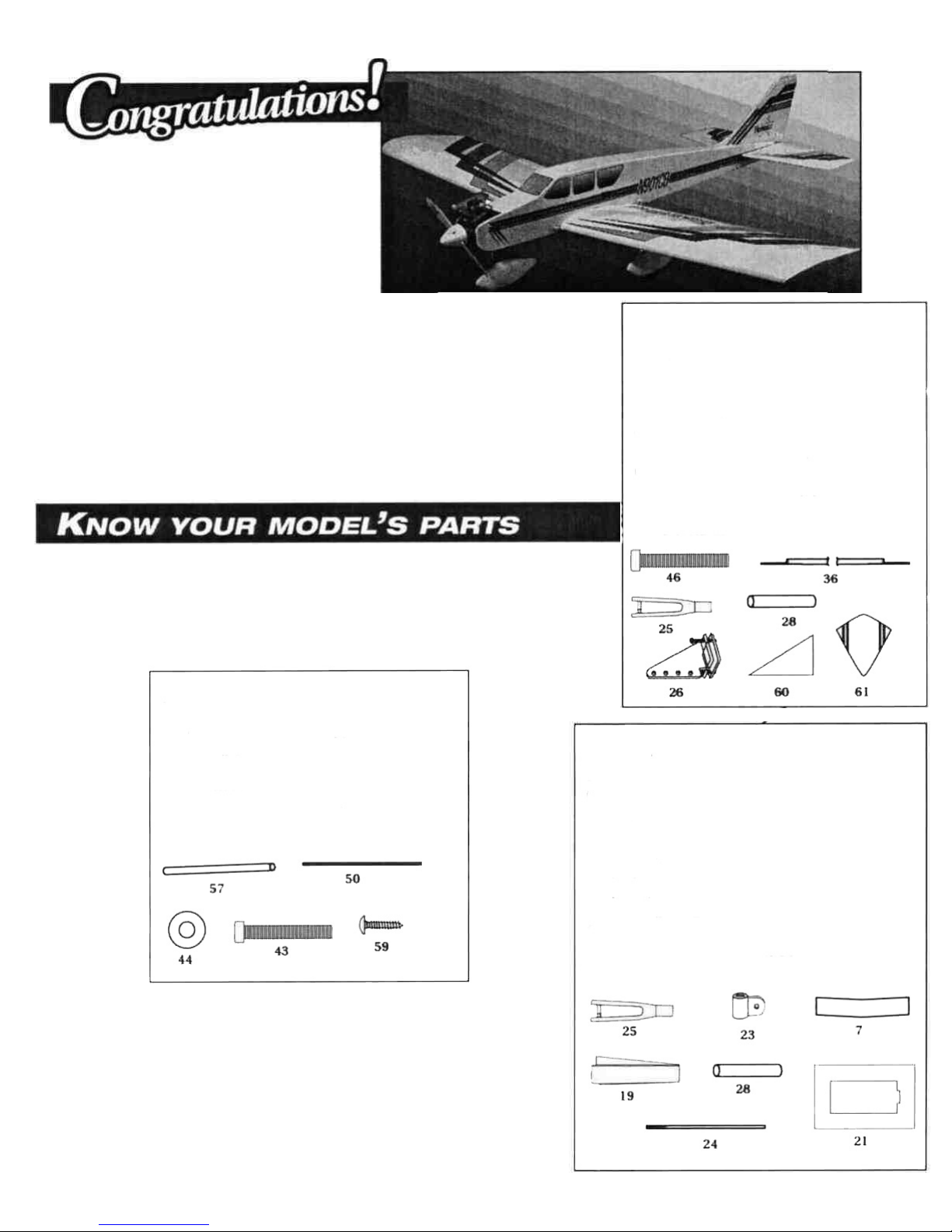
ou're about to build in just days what took aviation
pioneers years - a powered machine that flies. Specially
created for you and other first-time radio control modelers,
Hobbico's BrightStar offers nearly all the excitement of
piloting a real airplane...and develops skills that will take you
anywhere you want in your new hobby.
Take a moment now to match the box contents with the
items listed here. Following the BrightStar assembly
instructions will be quite easy if you identify and organize
the parts before you begin.
Engine Mounting Parts
Part # Quantity
43 6-32 x 3/4" machine screw.................4
44 #6 washers.......................................... 4
50 Wire pushrods....................................2
57 Pushrod guide tubes...........................2
59 #6 x 3/4" sheet metal screw................4
Tail Assembly
Please take your time and read through the instruction
manual before starting to build your new airplane. If
you have any questions, please feel free to give us a call
at (217) 398-8970. We hope you enjoy building and flying
the BrightStar 40.
Wing Assembly
Part# Quantity
1 Right
wing
with
aileron.............................
1
2 Left
wing
with
aileron...............................1
7 Plywood wing joiners................................3
19
Wing
center tape
.......................................1
21
Aileron
servo tray
......................................1
23 Aileron control horns................................2
24
Threaded
aileron
pushrods
......................2
25 Clevises......................................................2
28
Clear
clevis
retaining
tube........................
1
Part # Quantity
4 Horizontal stab and elevator.........1
5 Vertical fin and rudder...................1
25 Clevises ...........................................2
26 Control horns .................................2
28 Clear clevis retaining tube.............1
36 Dowel pushrods .............................2
46 2x15mm machine screws..............4
60 Dorsal fin ........................................1
61 Dorsal fin covering.........................1
2
Page 3
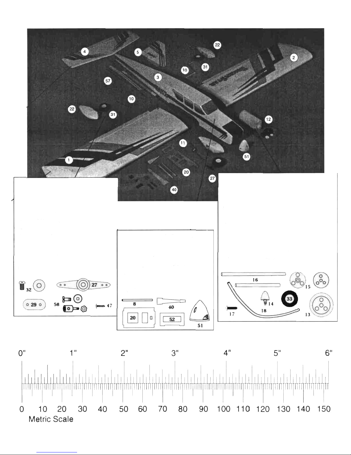
Landing Gear
Part# Quantity
10 Main landing gear strut .............2
11
Nose gear
strut
...........................1
22 Wheel Pant
.................................3
27 Plastic steering
arm
...................1
29 Landing gear strap (Nylon) .......4
31 Wheel ..........................................3
32 Wheel collar / 3x5mm screw.....7
47 2.5xl0mm sheet metal screw....4
58 Pushrod connector ....................2
62 Landing gear strap (Metal)........3
* Sketches shown are not
actual size or to scale.
Inch Scale
Fuselage & Parts
Part # Quantity
3 Fuselage .................................1
8 Wing mounting dowel...........2
20 Servo tray ...............................1
40 Stabilizer mounting base......l
51 Spinner...................................1
52 Servo tray support.................1
Fuel Tank & Parts
Part # Quantity
12 Fuel tank ..............................................1
13
Rubber tank
stopper
...........................1
14
Fuel pick-up weight
(clunk)
...............1
15 Plastic stopper disk
(one large and
one
small)
...................2
16 Aluminum fuel tubing
(one short and two long)
....................3
17
3xl8mm
sheet metal screw
................1
18
Silicone fuel
line..................................1
33 Foam tank collar..................................1
3
Page 4
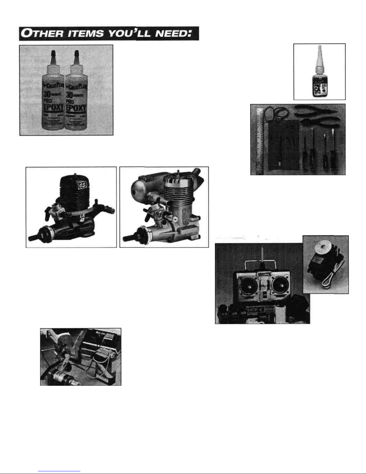
Glues
Choose a high quality 6-minute and 30-minute epoxy, such
as Great Planes* Pro- Epoxy, which has been formulated
especially for R/C model building. Pro Epoxies offer a strong
bond and a variety of curing times suited for every step of
assembly. You'll also need a 1 oz. bottle of thin and a 1 oz.
bottle of medium CA (Cyanoacrylate), plus rubbing alcohol
for easy epoxy cleanup.
Hardware
Tools and accessories required for assembly
include a hobby knife, small and large Phillips
screwdrivers, needle nose pliers, drill with
1/16", 11/64", 5/64", 3/32", 5/32" and 3/16"
bits, ruler, #64 rubber bands, one foot of
medium fuel tubing and petroleum jelly
Model Engine
Power your BrightStar with any high-quality,
.40 - .46 size model engine. The O.S. .40 LA is a
fine engine for this plane. Look for features such
as easy break-in, easy starting, efficient
carburetion and low maintenance. Check the
manufacturer's recommendations for propellers
to use with your engine.
Radio Equipment
To control your BrightStar's "flight path," you'll need a 1991
legal 4-channel aircraft radio system with four standard
servos. Many 4-channel radios include just three. You may
need to purchase the fourth separately. Hobbico Command
servos are available singularly and will work great for this
plane. The servos, battery pack and radio receiver will be
mounted onboard your model and need to be cushioned
from jolts and vibration. Half-inch thick foam rubber sheets
(HCAQ1050) are available for this purpose.
Getting Ready for Flight
Your Hobbico BrightStar can be ready for takeoff in as little as 16-20 hours.
Your hobby dealer or flying instructor (see next page) can help you decide what
accessories you'll need for flight. Most are one-time-only purchases - like a
glow plug igniter (see glossary), fuel pump, and "chicken stick" or electric
starter. You will also need to obtain model glow fuel. Use glow fuel with a
10-15% nitro content to keep your engine performing at its peak.
General Items Required
Mixing Sticks (GPMR8055)
Epoxy Mixing Cups
Clothespins
Foam Rubber (HCAQ1050)
String
Felt-tip Pen
Easy-Touch" Bar Sander
(GPMR6170)
150-grit sandpaper
(GPMR6183)
Adjustable Wrench
Masking Tape
Medium 3/32" Fuel Tubing
(GPMQ4131)
Paper Towels
T-pins
Wire Cutter
Epoxy Brush
Steel File
Wax Paper
4
Page 5
If you're a beginner, the best way
to begin flying your BrightStar is
with an experienced R/C pilot or
flying instructor at your side. You'll
learn faster and avoid risking your
model before you're truly ready
to solo.
Where do you find an instructor?
Ask at your local hobby shop.
They'll have information about
flying clubs in your area whose
membership includes qualified
instructors. You should also join the
Academy of Model Aeronautics
(AMA), a 165,000 member-strong
national organization with more
than 2,300 chartered clubs across
the country. Through any one of
them, instructor training programs
are available. Contact the AMA at
the address or phone number
below.
Academy of Model Aeronautics
5151 East Memorial Drive
Muncie, IN 47302-9252
(800)435-9262
Fax(317)741-0057
Before you fly:
1. Make sure that no other fliers are using your
radio frequency.
2. Your radio transmitter must be the FIRST thing you
turn ON, and the LAST thing you turn OFF.
3. Double check all control surfaces, making sure they arc
secure and move in the proper direction.
4. Make sure that the transmitter & receiver batteries are
fully charged.
Fuel storage and care:
1. Do not smoke near your engine or fuel.
2. Store all engine fuel in a safe, cool, dry place, away
from children and pets. Model fuel will evaporate, so
make sure that you always store it with the
cap secure.
When starting and running your engine:
1. Always wear safety glasses.
2. Make certain that your glow plug clip is securely
attached to the glow plug and cannot pop off,
possibly falling into the spinning propeller.
3. Use a "chicken stick" or electric starter to start the
engine - NOT your fingers.
4. Make sure that the wires from your starter and glow
plug clip cannot become tangled with the spinning
propeller.
5. Do not stand at the side of the propeller when you
start or run the engine. Even at idle speed, the
spinning propeller will be nearly invisible.
6. If any engine adjustments are necessary, approach
the engine only from behind the spinning propeller.
90-Day Limited Warranty
If you, as the original owner of this model, discover a defect in parts
or workmanship within 90 days of purchase, Hobbico will repair or replace it, at
the option of our authorized U S repair facility, Hobby
Services, without charge Our liability does not include cost of shipping to us
However, Hobby Services will pay shipping expenses to return your model to you
You must provide proof of purchase, such as your original purchase invoice or
receipt, for your model's warranty to be honored
This warranty does not apply to damage or defects caused by misuse or
improper assembly, service or shipment. Modifications, alterations or repair by
anyone other than Hobby Services voids this warranty We are sorry, but we
cannot be responsible for crash damage and/or resulting loss of kits, engines,
accessories, etc
Repair Service
Your BrightStar 40 must be returned directly to Hobby Services for warranty
work The address is Hobby Services, Attn Service Department, 1610 Interstate
Drive, Champaign, IL 61821-1067 Phone (217) 398-0007, or for product
information and technical support please contact us at (217) 398-8970
Please follow the instructions below when returning your model This will
help our experienced technicians to repair and return It as quickly
as possible
1 ALWAYS return your entire system, including airplane and radio.
2 Disconnect the receiver battery switch harness and make sure that the
transmitter is turned off Disconnect all batteries and drain all fuel
3 Include a list of all items returned and a THOROUGH, written explanation
of the problem and service needed If you expect the repair to be covered
under warranty, also include your proof of purchase
4 Include your full return address and a phone number where you can be
reached during the day
If your model is past the 90-day warranty period or is excluded from warranty
coverage, you can still receive repair service through Hobby Services at a
nominal cost Repair charges and postage may be prepaid or billed COD
Additional postage charges will be applied for non-warranty returns All repairs
shipped outside the United States must be prepaid in U S funds only
All pictures, descriptions and specifications found in this instruction manual
and on the product package are subject to change without notice
5
Page 6
Special Note:
You should charge your radio system before starting to
build. Following the manufacturer's directions, connect
your transmitter and receiver batteries to the system's
charger. This way the radio will be ready when it is time
to install and test the components.
Prepare the wing joiners
both sides of one of the wing joiners. Sandwich this
coated joiner between the remaining two. Make sure
that the centerlines drawn in step 1 are visable on both
sides of the assembly. Quickly proceed through the
following steps (3 and 4) before the glue cures.
Remove the excess epoxy
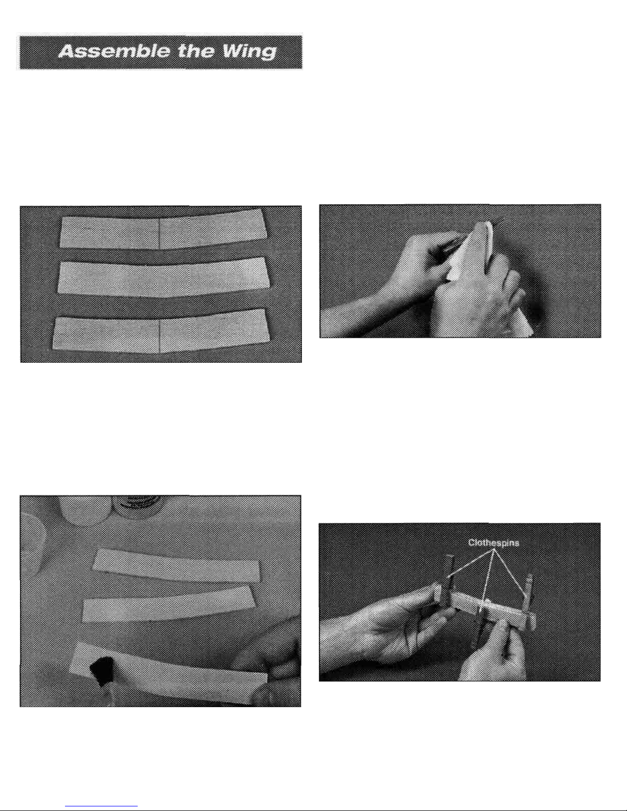
D 1. Locate the three 1/8" (3mm) die-cut plywood
wing joiners. Arrange the "V'-shaped joiners in the
same orientation as they will be glued together. Sand
off any bumps from the edges. Draw a centerline on
two of the joiners as shown.
D 3. Excess epoxy will squeeze out of the seams
between the joiners and must be removed before the
epoxy is allowed to cure. Use a paper towel and
rubbing alcohol to remove the excess epoxy.
Glue the wing joiners
Note: Please read steps 2 through 4 before mixing epoxy.
D 2. Mix approximately 1/4 oz. (7.5ml) of 30-minute
epoxy using a mixing stick and a cup. Using a mixing
stick or epoxy brush, apply an even coat of epoxy on
Clamp the wing joiner
D 4. Use clothespins to clamp the wing Joiners firmly
together. If any more epoxy squeezes out, remove it
using a paper towel. Make sure the joiners are evenly
lined up with each other. Set the joiner assembly aside
until the epoxy has fully cured.
6
Page 7
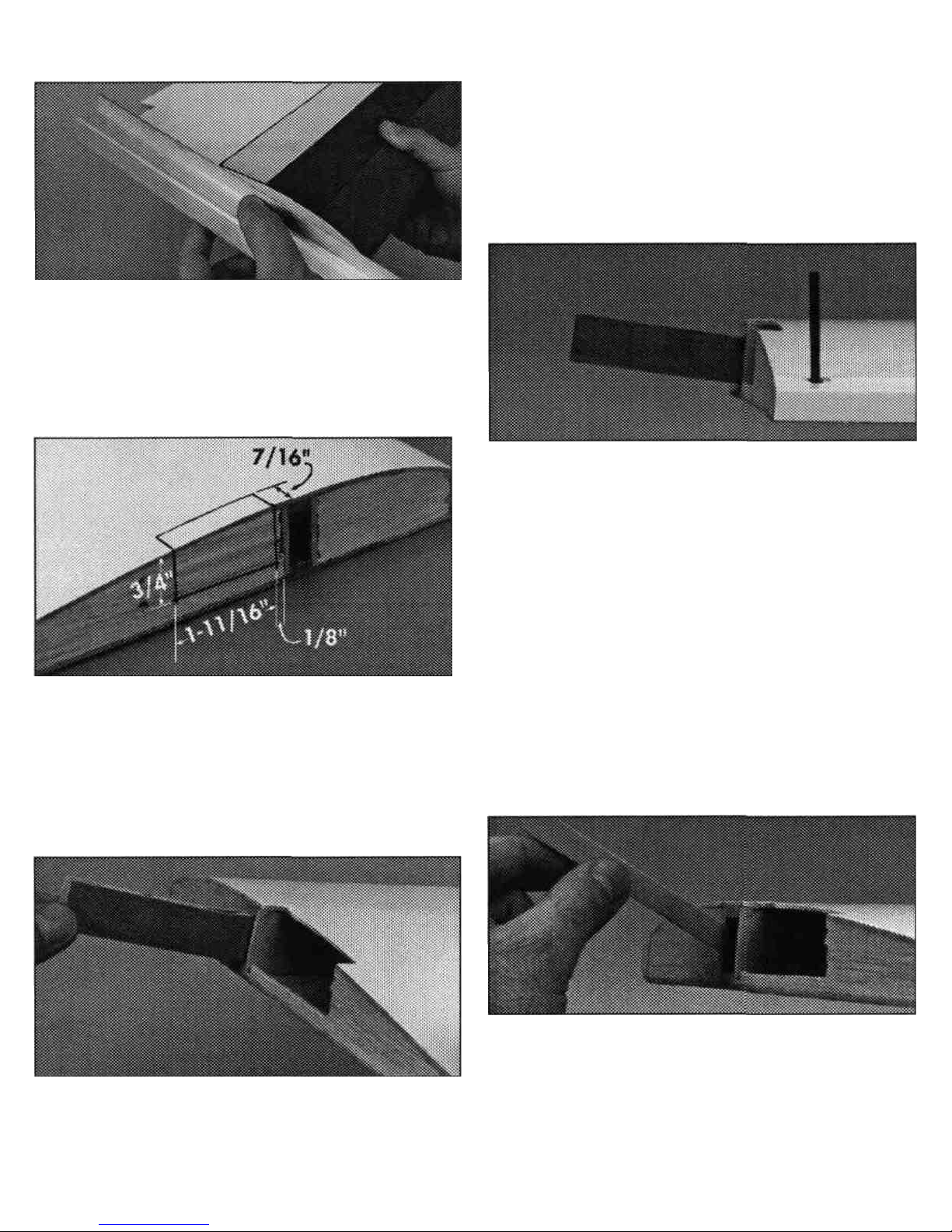
Even the edges
D 5. Using a bar sander or similar tool, sand the wing
roots so they will fit together with no gaps. Do not sand
too much or the dihedral angle could change.
Mark the wing servo cavity
D 6. Mark the aileron servo location on both wing
panels using a felt-tip pen. Using a hobby knife, cut an
opening into both panels following the lines you
just drew.
wing joiner will not fit in the cavity, lightly sand any
excess epoxy or uneven surfaces from the joiner edges,
sides and ends.
Caution: A snug fit is desirable between the joiner and
the wing cavity. Do not sand excessively.
Viewing the wing dihedral
D 8. Pay close attention to the orientation of the wing
joiner in relation to the wing panel, creating the
dihedral angle as shown. Test fit the wing panels
together. They should fit flush against each other
without gaps.
Note!
When performing the following steps, be sure
to use a sufficient amount of epoxy to form a complete
and solid bond between the plywood wing joiner and
the two wing halves. This is the most important glue
joint in the entire airplane.
Please read through the following three steps before
mixing any epoxy. You must complete these steps
within 20 minutes from the time you mix the epoxy.
Glue the joiner
Test fit the wing joiner
D 7. Test fit the wing joiner in both wing panels by
sliding the joiner into the joiner cavity in the wing. The
joiner should slide in snugly up to the centerline. If the
D 9. Mix 3/4 oz. (22ml) of 30-minute epoxy. Use a
mixing stick or epoxy brush to apply epoxy to all four
sides of the joiner cavity. Insert the joiner into the
cavity up to the centerline marked on the joiner plate.
Be sure you are installing the joiner correctly. Quickly
proceed to the next step.
7
Page 8
Apply epoxy to the wing root rib Test fit the aileron servo
D 10. Apply epoxy inside the joiner cavity of the
remaining wing panel. Next, coat the wing root ribs on
both panels. Quickly proceed to the next step.
Join the wing halves
D 11. Assemble the two wing halves with the tightest
seam possible. No gaps should be showing between
the two wing halves. Clean any excess epoxy from the
outside of the wing using a paper towel dampened
with rubbing alcohol. Use several strips of masking
tape on both sides to hold the wing halves tightly
together. Let the epoxy fully cure before continuing.
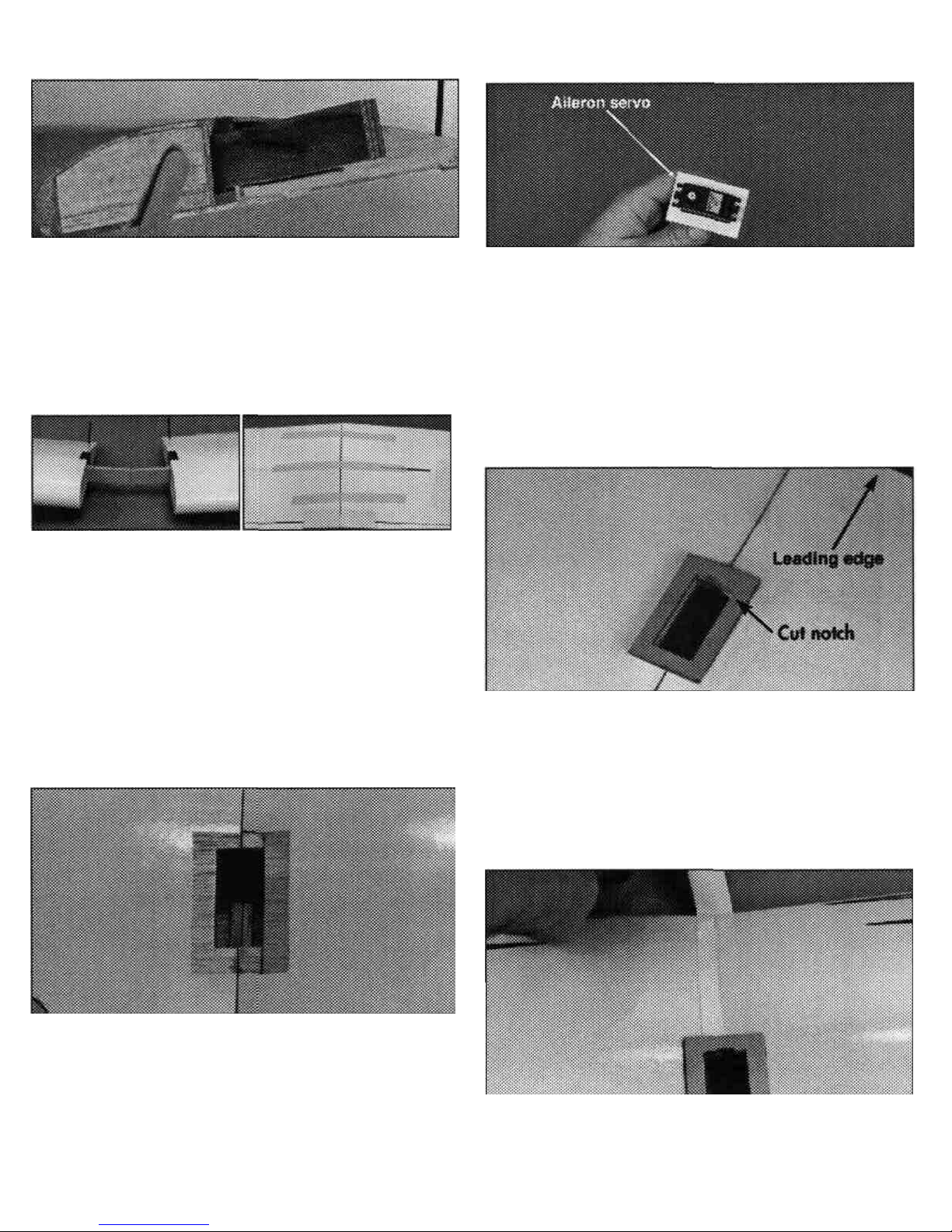
D 13. Test fit the aileron servo into the servo tray and
the hole in the top of the wing. Enlarge either hole, if
needed, with a hobby knife or a fine-toothed file until a
proper fit is achieved. The plywood tray should not
actually contact the the sides of the servo. Leave a
1/64" gap all the way around. Remove the servo. The
servo should not touch any of the wing surface.
Install the servo tray
Trim the covering
D 12. Hold the plywood aileron servo tray over the
hole in the top of the wing. Trace the outside of the tray
with a felt-tip pen and then remove the tray from the
wing. Carefully remove the covering within the lines
using a new #11 blade in a hobby knife, being careful
not to cut into the balsa wing sheeting.
D 14. Mix l/8oz. (3.5ml) of 6-minute epoxy to glue the
servo tray to the top side of the wing. Attach the servo
tray to the top of the wing. After the epoxy has cured,
cut a small notch in the servo tray to allow the servo
lead to pass through.
Apply the wing center tape
D 15. Starting at the front of the aileron servo tray,
apply the 1/2" (12.5mm) white wing center tape
8
Page 9
completely around the wing over the joint. A small
amount of pressure should be applied to make a
smooth seam.
Check the aileron hinge
D 16. Gently tug on each of the ailerons at each hinge
location. If any of the hinges are loose, reglue them as
described here. First, flex the surface all the way one
direction (DO NOT REMOVE THE AILERON).
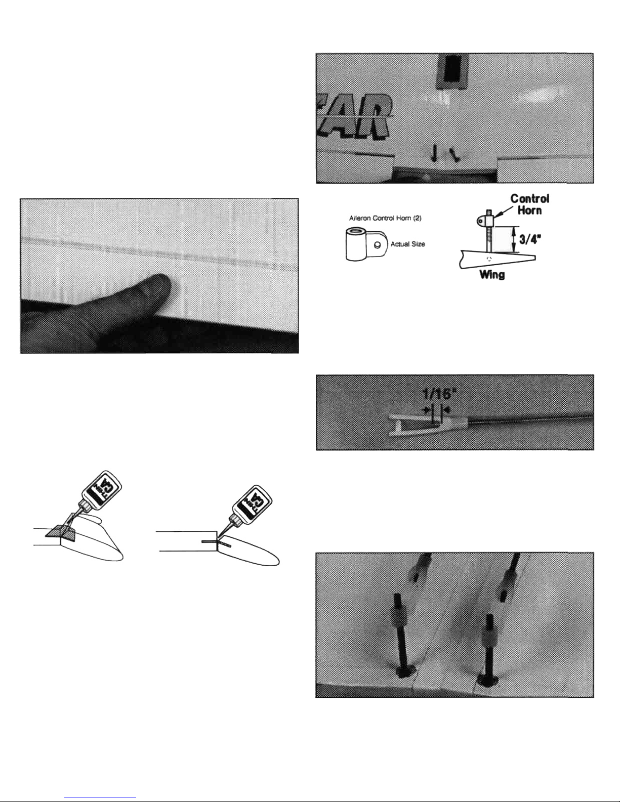
Install the aileron control horns
D 17. Thread the aileron control horns onto the torque
rods until there is 3/4" (19mm) of torque rod between
the wing and control horns.
Assemble the pushrods
Apply 5 drops of thin CA onto each hinge.
NOTE: Do not use CA accelerator as the CA must
"wick" into the slot. Use a paper towel to absorb any
excess glue. Wait a few minutes for the glue to cure,
then flex the surface the other direction and glue the
other side of the hinges in the same manner. Finally,
flex the surface back and forth several times to free up
the aileron.
D 18. Locate two plastic clevises and two 8 (203mm)
aileron pushrods. Thread the clevises onto the
threaded end of the pushrods until the rod protrudes
between the clevis forks 1/16".
Install the pushrods
D 19. Attach the pushrods to the aileron control horns.
Press the forks of the clevis together until they snap
into place.
9
Page 10

Securing the aileron pushrods Install the wing mounting dowels
D 20. Locate the 1/4" (6.5mm) diameter clear
retaining tube and cut two 1/4" (6.5mm) pieces. Slide
one piece onto each clevis to secure the connection
between the clevis and the horn.
This concludes the wing assembly for now. Tape the
pushrods to the wing to keep them in place until you
install the servo.
D 2. Insert both wing mounting dowels so they
protrude an equal distance on both sides. Mix 1/4oz.
(7.4ml) of 30-minute epoxy. Apply glue around the
dowels next to the fuselage and slide them in and out
to help force the glue into the holes. Using a paper
towel, spread the excess glue around the ends of the
dowels. This will fuelproof and add strength to the
wood. From the inside of the fuselage, apply more
epoxy around the dowels where they meet the sides of
the fuselage. These wing dowels will be used as anchors
for rubber bands to hold the wing in place. Wipe off all
excess epoxy with a paper towel and rubbing alcohol.
Locate the wing dowel holes
D 1. Locate the four round holes (two on each side of
the fuselage, see photo below for reference) and
remove the covering over each hole.
Caution: Do not cut out the rectangular holes in the
side of the fuselage.
Locate the stabilizer slot
D 3. Locate the horizontal stabilizer slot under the
covering on the tail section of the fuselage by pressing
lightly with your finger. The slot is located on both
sides of the tail. Using a hobby knife, carefully remove
the covering, exposing the slots.
NOTE: Do not cut into the wood around the slot.
10
Page 11

Install the plywood stabilizer mount Locate the vertical fin slot
D 4. Locate the 1/8" (3mm) plywood stabilizer
mounting base and test fit it into the bottom of the
horizontal stabilizer slot. Lightly sand the base if
necessary to obtain a good fit. Remove the base from
the fuselage.
D 7. Using your finger, locate the vertical fin slot on
the top of the fuselage. Remove the covering with a
hobby knife.
Check the rudder and elevator hinges
Glue the mount In place
D 5. Mix l/8oz. (3 5ml) of 30-minute epoxy. Using a
mixing stick, apply a generous amount of epoxy into
the slot and position the stabilizer mounting base
firmly in position. Remove any excess epoxy that
remains on the top of the stabilizer base and on the
outside of the fuselage with a paper towel and alcohol.
Remove the tail post
D 6. The balsa tail post is located at the rear of the
fuselage, behind the horizontal stabilizer slot. This post
was left for manufacturing alignment. The post must
be removed in order to insert the horizontal stabilizer.
Using a sharp hobby knife or razor saw, cut the post
even with the slot as shown in the picture.
D 8. Gently tug on the rudder and elevator at each
hinge location. If any of the hinges are loose, reglue
them as described here: First, flex the control surface
all the way one direction (DO NOT REMOVE THE
CONTROL SURFACE).
Apply 5 drops of thin CA onto each hinge. Use a paper
towel to absorb the excess glue. Wait a few minutes for
the glue to cure, then flex the surface the other direction
and glue the other side of the hinges. Finally, flex the
surface back and forth several times to free it up.
NOTE: Do not use accelerator on the hinges.
11
Page 12

Mark the centerline Align the stabilizer with the fuse
D 9. On the top surface of the horizontal stabilizer,
measure to find the exact center from side to side.
Draw a "centerline" using a felt-tip pen. Next, extend
that line onto the trailing edge, in the hinge gap, as
shown. (DO NOT MARK ON THE ELEVATOR.)
EQUAL MEASUREMENTS
D 11. Attach a piece of string with a T-pin to the center
of the fuselage as shown. Hold the string to one corner
of the horizontal stabilizer. The distance from the pin
to the horizontal stabilizer must be exactly the same to
both corners.
Mark the stabilizer location
Align the stabilizer with the wing
(DO NOT USE GLUE IN THIS STEP)
D 10. Insert the stabilizer into the horizontal stabilizer
slot so it is centered in the fuselage (A). Place the wing
onto the fuselage and secure it with two rubber bands
view the plane from the rear to check for proper
alignment. The stabilizer should be parallel with the
wing (B). If not, sand the high side of the stabilizer
mounting plate a little at a time until correct.
D 12. With the stabilizer properly aligned, use a felt-tip
pen to trace a line around the tail of the airplane on the
top and bottom of the horizontal stabilizer.
Remove the center covering
D 13. Remove the stabilizer and draw two additional
lines, on the top and bottom, 1/16" inside the lines
12
Page 13

drawn in the previous step. Next, carefully cut through
the covering using a new #11 knife blade at the inside
lines and remove the covering from the center. Do not
cut the wood under the covering! This would seriously
weaken the stabilizer and could easily cause the
stabilizer to break in flight. If the stab breaks the plane
may crash, so be very careful when you make this cut.
If the covering is not removed from the stabilizer a
proper bond cannot be achieved.
Install the Dorsal Fin
Install the stabilizer
D 14. Mix l/4oz. (7.5ml) of 30-minute epoxy. Using a
mixing stick, place epoxy inside the horizontal stabilizer
slot on all sides including the horizontal stabilizer
mount. Place more epoxy onto the bottom and top of
the stabilizer where you removed the covering. Insert
the stabilizer from the rear and adjust the alignment.
Wipe off any epoxy that squeezes out using a paper
towel dampened with rubbing alcohol. Recheck the
alignment, several times while the epoxy cures.
Install the vertical fin
90°
D 16. Locate the precut dorsal fin and decal. Apply the
decal to the dorsal fin, starting at the top and working
the decal down the sides. Trim any of the excess decal
so that it doesn't hang from the bottom of the filler.
Carefully trim away the covering from the fuselage
where the filer will be positioned. Glue the filler in
place using Medium CA.
Cut the rudder pushrod exit
D 17. The precut rudder pushrod exit hole is located
on top of the fuselage on the left side of the fin. Use a
hobby knife to remove the covering from the rudder
pushrod exit hole.
Cut the elevator exit
D 15. Test fit the vertical fin into the slot in the top of
the fuselage. Sand the edges of the slot if necessary for
a snug fit. When fit properly the bottom of the vertical
fin will rest firmly against the top of the horizontal
stabilizer. Mix l/4oz. (7.5ml) of 30-minute epoxy.
Using a mixing stick, apply epoxy to the top of the
horizontal stabilizer through the slot. Apply epoxy to
the sides and bottom surfaces of the fin base that have
balsa wood exposed. Insert the fin into the slot. Check
for a 90° angle between the fin and the horizontal
stabilizer when viewing from the rear. Check this
alignment several times as the epoxy cures. (You may
find it beneficial to hold the fin in place with tape until
the epoxy cures.)
D 18. The precut elevator pushrod exit hole is located on
the right side of the fuselage. Locate the exit hole by
gently running your finger along the bottom side of the
13
Page 14

fuselage over the covering. It should be located
approximately 1/2" in front of the stabilizer where
shown. Use a hobby knife to remove the covering from
the elevator pushrod exit hole.
straps (from plastic parts tree) over the struts so they
are approximately 3/4" from the ends of the channel.
Mark the holes using a felt-tip pen.
Locate the landing gear channel
D 19. There is a channel for the main landing gear on
the bottom of the wing. Locate this channel by running
your finger over the covering on the bottom of the
wing. Use a hobby knife to remove the covering from
this channel.
Drill the fuselage
D 22. Drill four holes for the landing gear straps using
a 1/16" (1.6 mm) drill bit.
Mount the struts
Prepare the channel for the gear
D 20. Test fit the chrome wire landing gear struts into
the holes. If they will not go in easily, enlarge the two
holes using an 11/64" drill bit. Next, use the drill bit or
hobby knife to bevel the inside corners of the holes so
that the bend in the wire will fully seat into the holes.
Install the main landing gear struts
D 23. Use eight 2.5xl0mm self-tapping screws to
fasten the landing gear straps to the bottom of the wing
over the struts.
Engine Selection
D 24. Steps 25 through 42 show the installation of
components for a 2-stroke engine. If you are planning
to install a 4-stroke engine, you will need to install the
throttle pushrod on the opposite side of what is shown
in the photos. Pay close attention to any special notes
covering 4-stroke installation in the text.
Glue the throttle guide tube in place
D 21. Position the wire landing gear strut in the hole
inside the channel. Center the two nylon landing gear
D 25. Use sandpaper to roughen the outside of both
plastic pushrod guide tubes and clean them with a
14
Page 15

paper towel dampened with rubbing alcohol. This will
help the glue adhere to the tubes. Insert one of the
tubes into the upper hole in the firewall. Position the
tube so that approximately 1" protrudes out of the
firewall. Mix l/8oz. of 6-minute epoxy and glue the
guide tube into the hole in the firewall.
Note: If you are installing a 4-stroke engine, you will
need to drill a new 5/32" hole for the throttle pushrod.
Drill this hole so it lines up behind the carburetor arm
on your engine. The predrilled hole is not needed and
should be plugged with 6-minute epoxy.
Make "Z" bends in the wire
D 28. Make a Z-bend at only one end of each of the
1/16" x 18" wire pushrods using needle nose pliers.
NOTE: Hobbico offers pliers that easily make perfect
Z-bends (HCAR2000). See your hobby dealer.
Trim the steering arm
Drill the steering pushrod exit hole
D 26. Drill a 5/32" hole through the firewall, 5/16"
from the bottom and 5/8" from the inside edge of the
fuselage side.
D 29. Locate the black plastic steering arm. Hold the
steering arm in your hand so that the screw hole is
facing you. Using a wire cutter, remove the right side of
the
arm.
Note: All directions are based upon you sitting in
the cockpit.
Install the steering pushrod
Install the steering guide tube
D 27. Slide the remaining guide tube into the 5/32"
hole you just drilled so about 2" - 3" protrudes. Mix
1 /8oz. of 6-minute epoxy. Glue the tube into the hole
and into the lower left notch inside the fuselage. Once
the epoxy has cured, trim off this tube so it is flush with
the firewall.
D 30. Attach the "Z" bend of one of the wires into the
hole closest to the center of the black plastic steering
arm. Slide the wire into the plastic guide tube so that
the screw hole on the steering arm is facing forward.
15
Page 16

Install the nose gear strut
D 31. Install the nose gear strut through the steering
arm, followed by a 4mm collar. Slide the strut through
the lower lug on the engine mount. Slide the strut up so
that the coil is about 1/4" below the bottom of the
fuselage. Tighten the wheel collar to the strut using a
3 x 5mm machine screw.
Position the steering arm
D 32. Rotate the nose gear strut so that the wheel
(once installed) will point straight ahead. Swing the
steering arm so it is approximately 1/2" from the
firewall. Tighten the arm to the strut using a 3 x 8mm
screw. The screw will leave a mark on the strut. Remove
the strut and file a small flat at this mark. This will keep
the steering arm from slipping on the strut.
Assemble the fuel tank plug
D 33. Push one long and one short aluminum tube
through the black rubber stopper - the third aluminum
tube will not be used. Place the two white plastic disks
over the tubes. The larger disk should go towards the
outside. The nub on the small disk should face away
from the rubber stopper. Insert the 3 x 18mm
self-tapping screw through the larger disk, rubber plug
and then into the smaller disk. Do not tighten the
screw at this time.
Bend the vent tube
D 34. Bend the longer tube (pressure tube) up as
shown so that it will come within 1/16" from touching
the top of the tank when installed. Use your fingers to
bend the tube, being careful not to kink it closed.
Install the clunk
D 35. Locate the metal fuel pick-up weight (often
referred to as the "clunk") and the fuel tubing. Cut the
fuel tubing so it is 3-1/2" long. Attach the fuel tubing to
the short aluminum tube and to the clunk.
Install the stopper
D 36. The stopper assembly can now be inserted into the
tank. The pressure tube should be adjusted so the tube is
16
Page 17

pointed straight up just under the top of the tank. The
rubber stopper must seat over the lip of the tank. Make
sure that the tubes are positioned side-to-side. Tighten
the stopper by turning the screw. Do not overtighten or
you may strip the threads in the plastic disk.
Install the foam tank collar and bend
the tubes
D 37. Locate the foam tank collar. Remove the
inner foam circle and place the collar around the
neck of the fuel tank. Bend the aluminum tubes
outward slightly, as shown.
Install the tank
D 38. Insert the fuel tank into the fuselage. Make sure
the foam collar is seated well against the firewall.
Attach fuel tubing to the tank
D 39. Cut two 6" pieces of medium silicone fuel tubing
(not included). Slide one piece onto each of the
aluminum tubes coming from the fuel tank.
Install the throttle pushrod
D 40. Attach the "Z" bend of the remaining 1/16" wire
pushrod into the inside hole of the carburetor
control arm.
Mount the engine
D 41. Insert the throttle pushrod into the pushrod
guide tube and position the engine on the mount so
that the face of the engine thrust washer is 1/4"
forward of the fuselage sides. Align the engine so the
crankshaft is pointing straight forward.
Using the engine mounting plates, 6/32" lock washers,
6/32" nuts and 6/32" x 3/4" screws, secure the engine
into position.
17
Page 18

Install the muffler Install the spinner
D 42. Install the muffler onto the engine using the
screws that came with the engine. Attach the fuel
tubing from the "pressure tube" in the fuel tank to the
muffler pressure tap. Attach the fuel pick-up tube from
the fuel tank to the carburetor. NOTE: You may wish to
shorten the fuel lines for more direct routing. Make
sure that the lines do not get any kinks which could
restrict fuel flow.
Attach the propeller to the engine
D 43. Install the spinner backplate, prop, prop washer
and the prop nut onto the engine. Position the prop so
it is horizontal when the engine is against its
compression (the point at which you feel resistance
when you turn the crankshaft counterclockwise). This
is a good habit to get into when installing props onto
model airplanes. If the engine quits during flight, the
prop will stop horizontally, therefore reducing the
chance of prop breakage if you are forced to land on
rough terrain. Use an adjustable wrench (not a pliers)
to securely tighten the prop nut.
D 44. Trim the spinner cone propeller slots if
necessary so there is at least a 1/16" gap between the
cone and the prop. Once satisfied with the fit, attach
the cone with the screws provided. Be careful not to
overtighten these screws. They are threaded into
plastic which can strip out easily if they are
overtightened.
Prepare the servos
D 45. Install the rubber grommets and bushings
included with your radio system, onto the four servos.
Refer to your radio manual or the sketch for proper
installation of these items.
Install the servo tray support
D 46. Position the servo tray support in the fuselage
where shown. Glue it in place with thick CA.
18
Page 19

Install the servo tray Receiver and battery installation
D 47. Position the servo tray in the fuselage. You may
need to sand the edges and corners slightly for a good
fit. Glue it in place using thick CA.
Install the servos in the fuselage
D 48. Route the servo wires forward. Install the servos
into the tray as shown using the screws included with
the radio system. Enlarge the openings if needed.
Choose and trim the servo arms so they look similar to
the ones shown in the photo.
Install the aileron servo
D 49. Route the servo wires through the harness
notch that you made in the servo tray in step 14. Install
the servo.
D 50. Following the radio system's instruction manual,
plug the three servos into the receiver. Next, plug a
servo extension into the aileron channel of the receiver.
Finally, plug the switch into the receiver. Wrap the
receiver and battery pack in foam rubber (HCAQ1050)
using rubber bands or masking tape to hold the foam
in place. Install the battery and receiver into the
fuselage. The battery should be located directly behind
the fuel tank. The receiver should then be placed
directly behind the battery. Secure these components
in place using pieces of scrap wood (mixing sticks work
well) glued to the fuselage sides.
Mount the switch to the fuselage
D 51. Cut out the opening on the left side of the
fuselage for the switch and install it using the screws
included with the switch. We recommend using a Great
Planes Switch/Charge Jack (GPMM1000, shown above).
This makes it easy and convenient to charge your
receiver batteries. It is good practice to always install the
switch on the side opposite the engine's exhaust outlet.
19
Page 20

Prepare the pushrods Align the control horns
D 52. Locate the two wooden dowel pushrods and
apply thin CA to the ends of the shrink tubing on
both rods.
Install the pushrods
D 53. Insert the two pushrods, threaded end first,
through the fuselage and out the two pushrod exits at
the back of the fuselage. You may need to bend the rods
slightly to eliminate binding, but keep any bends to
a minimum. Excessive bending of the pushrod will
allow it to flex during operation.
Make the clevis retainers
D 54. Cut two 1/4" long pieces of the clear tube. Slide
one on each of the pushrods that protrude out of
the rear of the fuselage.
Install the two clevises
D 55. Screw a clevis onto each pushrod until the
threads protrude about 1/16" between the clevis forks.
Connect the control horns
D 56. Attach the two clevises to the control horns as
shown. Use the second hole from the outside for the
elevator and the third hole from the outside hole for the
rudder. Check to make certain that the pushrods do not
bind in the openings and that they operate smoothly.
CORRECT INCORRECT
D 57. Position the control horn on the elevator so that
the pushrod will work without binding. Mark the two
holes using a felt-tip pen. Make sure that the control
horns are positioned even with the hinge line (see
sketch). Repeat this process for the rudder.
Secure the control horns
D 58. Drill two 3/32" (2.4mm) holes straight through
the balsa elevator at the marks. Insert two 2 x 15mm
machine screws through the control horn and the
elevator, finally threading them into the control horn
backplate. Tighten the screws but do not crush the
balsa. Cut off the excess threads that stick out using a
wire cutter. Repeat this process for the rudder.
Attach the pushrods
D 59. Slide the clevis retainers over the clevis forks.
20
Page 21

Center the servos with your radio
D 60. Turn the transmitter on and then the receiver.
Center all of the trim levers on the transmitter and
place the throttle stick at its midway position. Turn off
the receiver and then the transmitter. By doing this,
your servos will be at their centered (neutral) position
when you connect the pushrods. Refer to the following
photos and replace or trim the servo arms as shown. To
do this, simply remove the servo arms and reposition
them on the splined servo output shaft. Be sure to
reinstall the screws.
Connect the pushrods
D 63. Make a "L" bend at each mark. Remove the servo
arms from the servos. Attach the rods to the servo
arms. Use the plastic keepers as shown.
Mark the pushrods
0 61. Holding the elevator in its neutral position, mark
the pushrod wire where it crosses the servo arm using a
felt-tip pen. Next, hold the rudder at its neutral
position and mark the rudder pushrod wire in the
same manner.
Cut the pushrods
D 62. Cut off the pushrods approximately 3/8" past
the marks. Removing the pushrods will make this and
the next step easier.
Note: Install the rudder pushrod in the outside hole of
the servo arm. Install the elevator pushrod into the
middle or outer hole. You may need to enlarge the
holes slightly on the arms. A 5/64" drill bit works great
for this. Reattach the servo arms in the same position.
Do not connect the rudder yet.
Support the pushrods
D 64. Support the pushrods using leftover pieces of
plywood from the servo tray. This will keep the
pushrods from flexing during operation.
Attach the pushrod connector
D 65. Install a pushrod connector on the rudder servo
arm. For the steering pushrod, position the connector
in the innermost hole of the arm. You may need to
enlarge the hole using a 5/64" drill bit. Thread the nut
onto the connector. The connector must be able to
rotate in the servo arm, so do not over-tighten the nut.
Place a small drop of thin CA onto the threads
21
Page 22

to lock the nut in place. Thread a 3 x 4mm machine
screw into the connector. Reattach the servo arms in
the same position. Be sure to reinstall the servo screw.
Install the steering pushrod
Connect the aileron servo
D 68. Hold the ailerons at neutral and mark the servo
arm where the pushrods intersect the holes. Make a
"L" bend at the marks and attach to the servo arms
using the plastic keepers.
D 66. Slide the wire steering pushrod into the pushrod
connector. Straighten the nose gear and tighten the
pushrod connector screw. Using a wire cutter, carefully
remove the excess wire, leaving only about 3/4"
remaining past the connector. Connect the rudder to
the outside hole of the servo arm.
NOTE: If there is any binding when the servo operates,
use a "Z" bend to connect the rudder to the servo arm.
Straighten the antenna
D 69. Unwind the antenna and straighten the wire to
its full length being careful not to stretch the wire. Do
not cut the antenna wire as this will decrease the range
and sensitivity of your receiver.
Drill an antenna exit
D 70. Using a 3/16" drill bit, drill a hole centered
approximately 3/4" behind the wing saddle on top of
the fuselage. Cut a 1/2" long piece of medium fuel
tubing and center it inside this hole.
Connect the throttle servo
D 67. Install the second pushrod connector onto the
throttle servo arm but do not apply CA glue to the
threads yet (you may have to move this connector later).
Slide the throttle pushrod wire through the connector.
Hand tighten this screw so that the carburetor is half
open. Final throttle adjustment will be made later. Using
a wire cutter, carefully remove the excess wire, leaving
only about 3/4" remaining past the connector.
NOTE: For a 4-stroke engine install the throttle servo
and the arm 180° to what the photo shows.
Securing the antenna
D 71. Route the antenna away from the servos, make a
strain relief from a spare servo arm and route the
antenna through the holes. Next, route the antenna up
through the antenna exit. Use a trimmed servo arm
and rubber band at the end of the antenna and attach
to a T-pin. Push the pin into the top of the fin. Adjust
the trimmed servo arm until there is a slight amount of
tension on the antenna wire. The rubber band should
be partially stretched. NOTE: Never push a pin through
the antenna or trim off the excess wire.
22
Page 23

Prepare the Wheel Pants
D 72. Trim the excess flashing from around the
opening for the wheel. Drill a 5/32" hole at the mark on
the raised side of the wheel pant as shown. Using this
hole as a guide, mark and drill a hole on the opposite
side of the wheel pant at the same location.
Install the wheels
D 73. Install the wheels and wheel pants by using the
parts in the following order: wheel pant, plastic spacer,
wheel and wheel collar. Secure the wheel pant in place
by attaching the steel wheel pant strap using two 2 x
8mm wood screws.
Attach the wing
D 74. Connect the aileron servo to the aileron
extension. Attach the wing onto the fuselage using 12
#64 rubber bands. Install 3 on each side first from front
to back. Then criss-cross the remaining 4. This will hold
the wing securely, but will allow it to pop off in the event
of a cartwheel on the ground, thus minimizing damage.
Check the control directions
1. Turn on the Transmitter and then the Receiver.
Standing behind the plane, make the following
movements with the transmitter and observe the
control surfaces.
ELEVATOR MOVES UP
RIGHT AILERON MOVES UP
LEFT AILERON MOVES DOWN
RUDDER
MOVES
RIGHT
CARBURETOR WIDE OPEN
4-CHANNEL RADIO SET-UP
(STANDARD MODE 2)
23
Page 24

If any of the servo movements are opposite, reverse the
servo direction with the servo reversing switches on
the transmitter.
low rates following the radio system's instructions If
your radio does not have dual rates, set up the plane
using the low rates first and increase the throws as you
get familiar with the plane.
Adjust the throttle
2 For added safety and convenience, the throttle
should be set up so that the engine can be stopped
using the throttle trim To do this, loosen the pushrod
connector screw and move the throttle pushrod so that
the carburetor is completely closed with the throttle
stick and trim lever on the transmitter fully back
(NOTE: If the carburetor does not fully close, adjust the
idle stop screw on the carburetor until it will) Next,
tighten the screw on the pushrod connector Test the
trim lever by advancing it to full This will be a fast idle
position with the carburetor barrel slightly open (about
1/32"). See sketch.
Aileron:
Low
rate
5/16" up
5/16" down
Elevator: 3/16" up
3/16" down
High rate
7/16" up
7/16" down
1/4" up
1/4" down
Rudder
7/8" left
7/8" right
OPEN SLIGHTLY (IDLE)
FULLY OPEN
These are the suggested deflections from center.
If you need more control movement, you should move
the clevis to a hole closer to the control surface or you
can install a larger servo wheel and move the rod at the
servo end further out from center If you have too
much movement, move the rod in the opposite
direction See sketches below:
Now move the throttle stick forward to full Make sure
that the carburetor barrel opens all the way See
sketch If it doesn't open far enough or opens too far
(bending the rod) move the pushrod connector in or
out on the servo arm and/or the carburetor arm to gain
or reduce movement Apply a small amount of thin CA
onto the threads of the pushrod connector The throw
will be correct when the carburetor barrel will stop
fully open at the same time the throttle stick reaches
full With the throttle set up properly, you should be
able to run the engine with the trim lever set midway to
the full position (adjusted for a smooth but slow idle)
Then when it is time to stop the engine, simply pull
back the trim to close the carburetor and the engine
will stop running
Adjust the control throws
3 Check the movement of the control surfaces Use a
ruler to match our measurements listed below If your
radio features dual rates, set up both the high and the
Moving the clevis outward on the servo arm
results in more pushrod movement
Moving the clevis inward on the control horn
results in more throw
24
Page 25

IMPORTANT
This section is very important and must not be
omitted! A model that is not properly balanced will
be unstable and possibly unflyable.
Check the lateral balance
1. An airplane that has been laterally balanced will
track better in loops and other maneuvers. With the
wing attached, gently lift the airplane by the spinner
and the bottom of the fuselage at the tail. You may
need an assistant to help you with this. If one wing tip
is noticeably heavy (the tip will drop) attach some
weight to the lighter tip until they are equal. Use Great
Planes "stick-on" lead weights (GPMQ4485) for
easy balancing.
Check the fore-alt balance
2. Check the fore-aft balance point, also referred to as
the "center of gravity" (CG). Accurately mark the balance
point on the top of the wing on both sides of the
fuselage. The balance point is located 3-5/8" back from
the leading edge. This is the balance point at which your
model should balance for your first flights.
The plane must be "ready to fly" (all components
installed) with an empty fuel tank before checking the
CG. Turn the model upside down and place your finger
tips or a balancing stand under the wing at the marked
balance point. Lift the model. If the tail drops, the
plane is "tail heavy" and you must add weight to the
nose. If the nose drops, the plane is "nose heavy" and
you must add weight to the tail. If possible, first
attempt to balance the model by changing the position
of the battery and receiver. If you are unable to obtain
good balance by doing so, then it will be necessary to
add weight to the nose or tail to achieve the proper
balance point.
You may wish to experiment by shifting the balance up
to 3/16" forward or back to change the flying
characteristics. Moving the balance forward may
improve the smoothness and arrow-like tracking, but it
may then require more speed for takeoff and make it
more difficult to slow down for landing. Moving the
balance aft makes the model more agile with a lighter,
snappier "feel." In any case, please start at the location
we recommend and do not at any time balance your
model outside
of
the range of 2 7/8" to 3-1/4" back
from the leading edge.
3 -3/16"to 3 -7/16" Use first CG
If you're a novice, there is one thing that you will need to
fly your BrightStar safely that is not furnished with the
kit: You will need a qualified instructor to teach you to
fly. No model ever made will let you teach yourself to fly
safely. It can be done, but you would be seriously risking
more than just the airplane. To find an instructor, you
should join an R/C flying club. If there is not a club
nearby, then you should find an experienced model pilot
who is willing to help you. The chosen instructor should
fly well enough to allow you to concentrate on your own
flying. If you are worried about your instructor crashing
your model, you will not be able to concentrate on
learning to fly. After you have found an instructor, you
should spend some time just talking with him about
what you will be trying to learn. He should inspect the
model to be certain that it is ready to fly. Listen to him
and learn from his experience.
Now that you have a good model and an instructor
whom you trust, you can go out and start learning to fly.
You can expect to be very nervous at first and you will
make some mistakes. There will be several instances
where the instructor will prevent you from crashing.
This will be unsettling, but the thing to do is jump right
back into flying the model (after your knees stop
shaking, of course). This is one of the most important
things about learning to fly model airplanes...you have
to fly! Fly as often as you can. Be sure to make several
flights each time you go to the flying field, but give
yourself time after each flight to calm down and discuss
the flight with your instructor. Spending some time after
each flight talking about what happened and what you
need to work on to improve your skills will pay off with
greater confidence in your own growing abilities.
25
Page 26

Charge the batteries
Follow the battery charging procedures in your radio
instruction manual. You should always charge your
transmitter and receiver batteries the night before you
go flying and at other times as recommended by the
radio manufacturer.
Balance the propeller
Balance your propellers carefully before flying. An
unbalanced prop is the single most significant cause of
damaging vibration. Not only will engine mounting
screws and bolts vibrate out, possibly with disastrous
effect, but vibration will also damage your radio
receiver and battery. Vibration will cause your fuel to
foam, which will, in turn, cause your engine to run
rough or quit.
We use a Top Flite Precision Magnetic Prop Balancer
(#TOPQ5700) in the workshop and keep a Great Planes
Fingertip Balancer (#GPMQ5000) in our flight box.
Find a safe place to fly
1. The best place to fly your R/C model is an AMA
(Academy of Model Aeronautics) chartered club field.
Ask your hobby shop dealer if there is such a club in your
area and join. Club fields are set up for R/C flying, which
makes your outing safer and more enjoyable. The AMA
can also tell you the name of a club in your area. We
recommend that you join the AMA and a local club so
you can have a safe place to fly and also have insurance
to cover you in case of a flying accident. (The AMA
address is listed on page 5 of this instruction book).
If there is not a flying club in your area, you need to find
a large open area, free of obstructions, with a smooth
surface that can be used as a runway. It should be
located at least 6 miles away from any other R/C
airplane operation and away from houses, buildings and
streets. A schoolyard may look inviting but it is too close
to people, power lines and possible radio interference.
Ground check the model
If you are not thoroughly familiar with the operation of
R/C models, ask an experienced modeler to check to
see that you have the radio installed correctly and that
all the control surfaces do what they are supposed to.
The engine operation must also be checked and the
engine "broken in." Follow the engine manufacturer's
recommendations for break in. Check to make sure all
screws remain tight, that the hinges are secure and that
the prop is on tight.
Range check your radio
Check the operation of the radio every time you fly.
This means that with the transmitter antenna
collapsed and the receiver and transmitter on, you
should be able to walk at least 100 feet away from the
model and still have control. Have someone help you.
Have them stand by your model and, while you work
the controls, tell you what the various control surfaces
are doing. Repeat this test with the engine running at
various speeds while an assistant holds the model. If
the control surfaces do not act correctly at all times, do
not fly! Find and correct the problem first.
Engine safety precautions
NOTE: Failure to follow these safety precautions may
result in severe injury to yourself and others.
Keep all engine fuel in a safe place, away from high
heat, sparks or flames, as fuel is very flammable. Do
not smoke near the engine or fuel; remember that the
engine exhaust gives off a great deal of deadly carbon
monoxide. Therefore do not run the engine in a closed
room or garage.
Get help from an experienced pilot when learning to
operate engines.
Use safety glasses when starting or running engines.
Do not run the engine in an area of loose gravel or
sand, as the propeller may throw such material in your
face or eyes.
Keep your face and body as well as all spectators away
from the plane of rotation of the propeller as you start
and run the engine.
Keep items such as these away from the prop: loose
clothing, shirt sleeves, ties, scarfs, long hair or loose
objects (pencils, screwdrivers) that may fall out of shirt
or jacket pockets into the prop.
26
Page 27

Use a "chicken stick" device or electric starter; follow
instructions supplied with the starter or stick. Make
certain that the glow plug clip or connector is secure
so that it will not pop off or otherwise get into the
running propeller.
Make all engine adjustments from behind the rotating
propeller.
The engine gets hot! Do not touch it during or after
operation. Make sure fuel lines are in good condition.
To stop the engine, cut off the fuel supply by pinching
the fuel line. Do not use hands, fingers or any body
part to try to stop the engine. Do not put anything into
the prop of a running engine.
AMA safety code (excerpt)
Read and abide by the Academy of Model Aeronautics
Safety Code, a portion of which is reprinted here:
GENERAL
1. I will not fly my model aircraft in sanctioned
events, air shows or model flying demonstrations until
it has been proven to be airworthy by having been
previously successfully flight tested.
2. I will not fly my model aircraft higher than
approximately 400 feet within 3 miles of an airport
without notifying the airport operator. I will give rightof-way and avoid flying in the proximity of full-scale
aircraft. Where necessary, an observer shall be utilized
to supervise flying to avoid having models fly in the
proximity of full-scale aircraft.
3. Where established, I will abide by the safety rules
for the flying site I use and I will not willfully and
deliberately fly my models in a careless, reckless
and/or dangerous manner.
6. I will not fly my model unless it is identified with
my name and address or AMA number, on or in the
model.
8. I will not operate models with pyrotechnics (any
device that explodes, burns or propels a projectile of
any kind)...
RADIO CONTROL
1. I will have completed a successful radio
equipment ground range check before the first flight of
a new or repaired model.
2. I will not fly my model aircraft in the presence of
spectators until I become a qualified flyer, unless
assisted by an experienced helper.
3. I will perform my initial turn after takeoff away
from the pit or spectator areas and I will not thereafter
fly over pit or spectator areas unless beyond my
control.
4. I will operate my model using only radio control
frequencies currently allowed by the Federal
Communications Commission...
It is best if you let the instructor test fly the model first.
Once he has flown the model he will adjust the trim to
eliminate any turning, climbing or diving tendencies
that he found on the test flight. This will help make
your first flights much easier and safer. When first
learning to fly use the "low rates" for smoother control
(see page 24).
One thing to keep in mind with R/C models (whether it
be cars, boats or planes) is that the rudder and aileron
controls may seem to "reverse" when the model is
moving toward you. For example, if you are flying
toward yourself and you give a right control input
(ailerons or rudder), the model will move to your left.
The fact of the matter is, of course, that the controls are
not reversed and the aircraft did actually enter a right
turn. The plane does move to your left from your
vantage point, but if you imagined yourself in the
cockpit you would realize the plane turned to the right
as commanded. All it takes is a little practice to
maintain proper orientation of your aircraft, but that's
why we recommend finding an instructor.
There is a memory aid that may help keep you out of
trouble when the plane is flying toward you — "put the
stick under the low wing." In other words, move the
stick in the direction of the low wing to raise that wing.
When you are comfortable flying the aircraft, you can
practice using the rudder along with the ailerons to
'coordinate' the turns. Usually, a small amount of
rudder applied in the direction of the turn will keep the
tail following in the exact same track as the nose.
27
Page 28

Ground Handling
Start with learning to steer the model on the ground
using the rudder and throttle. You should learn to
guide the airplane on the ground at various speeds and
directions. Be careful- you do not have brakes, so do
not get close to any obstacles.
Takeoff
Line up as straight into the wind as possible. Gradually
advance the throttle to get the model rolling. Advance
the throttle to full. Using rudder inputs, guide the plane
straight down the runway. Let the plane get up to flying
speed on the ground before lifting off. Once up to speed,
lift off by smoothly applying a little up elevator and
climb out gradually. Once a positive angle of attack is
achieved relax the up elevator input. Do not try to gain
altitude or turn until the airplane gains additional speed.
Flying
We recommend that you take it easy with your new
model for the first several flights and gradually "get
acquainted" with the airplane as your engine gets fully
broken-in. As you will see, this airplane is smooth and
very predictable. Your confidence will grow to the point
that flying is more fun than ever. Just remember to take
your time. Follow your instructor's advice and learn to
control the model in the many basic maneuvers
possible.
Your first flights should consist of mostly straight and
level flight with gentle turns to keep the model over
the field. These flights will give you practice at
coordinating your control inputs and maintaining the
proper orientation of the airplane. As mentioned
earlier, turns are accomplished by banking the aircraft
with the ailerons, then gently adding some back stick
(up elevator). Enough back stick should be held in to
keep the aircraft at a constant altitude —to stop
turning, apply opposite aileron (or rudder) to level the
wings, then release the sticks. The most common
mistake when learning to fly is over-control. Think of
pressure instead of large movements of the control
sticks. Add and practice one maneuver at a time,
learning how your BrightStar behaves in each one. For
ultra-smooth flying and normal maneuvers, we
recommend using the "low rate" settings as listed on
page 24. High rate control throws will give your
BrightStar enough control for loops, barrel rolls and
many other basic aerobatic maneuvers.
Landing
Because this is not a high-wing trainer, the BrightStar
will need a slightly different approach to landing.
Keeping the wings level during approach is
recommended to prevent "scuffing" the wing tips. The
BrightStar, being a low-wing trainer, will also land
slightly faster because it doesn't have the "glide
tendencies" of a high-wing trainer.
As with takeoffs, always land into the wind. Adding 2 to
3 "clicks" of up elevator trim will help slow the model
and allow easier landings. Line up with the runway and
reduce the throttle to idle. Glide the model down using
ailerons to keep the wings level and elevator to control
altitude. Be careful not to use too much elevator at
slower speeds. This could cause the airplane to stall too
close to the ground. If the airplane is coming in short,
gradually increase the throttle to get to the runway. If
you come in too fast, raise the throttle slowly and abort
the landing. Do not force the plane to land. Try again
with a slightly lower approach. Just before touchdown,
add in a little more elevator to flare the airplane for a
smooth touchdown. Perfect landings are difficult, so
practice them often.
Thank you for choosing the BrightStar. We hope that it
will be one of many, in a lifetime enjoyment of radio
control airplanes.
 Loading...