

Page 1
ASSEMBLY INSTRUCTIONS
90-Day Limited Warranty
If you, as the original owner of this model, discover defects in pans or workmanship wilhin 90 days of purchase, Hobbico will repair or replace it - at the option
of our authorized U.S. repair facility, Hobby Services - without charge. Our liability does not include cost of shipping to us. However, Hobby Services will pay
shipping expenses lo return your model to you. You must provide proof of purchase, such as your original purchase invoice or receipt, for your model's
warranty to be honored. This warranty does not apply to damage or defects caused by misuse or improper assembly, service or shipment. Modifications,
alterations or repair by anyone other than Hobby Services void this warranty. We are sorry, but we cannot be responsible for crash damage and/or resulting
loss of kits. engines, accessories, etc.
Repair Service
Your Avistar must be returned directly to Hobby Services for warranty work. The address is: Hobby Services. Attn: Service Department. 1610 Interstate Drive,
Champaign, II. 61822 Phone: (217) 398-0007. Please follow the instructions below when returning your model. This will help our experienced technicians to
repair and return it as quickly as possible.
1. ALWAYS return your entire system, including airplane and radio.
2. Disconnect the receiver battery switch harness and make sure that the transmitter is turned off Disconnect all batteries and drain all fuel.
3. Include a list of all items returned and a THOROUGH, written explanation of the problem and service needed. If you expect the repair to be covered under
warranty, also include your proof of purchase.
•I.
Include your
full
return
address
and a phone number where
you
can
be
reached during
the
day.
If your model is past the 90-day warranty period or is excluded from warranty coverage, you can still receive repair service through Hobby Services at a
nominal cost. Repair charges and postage may be prepaid or billed COD. Additional postage charges will be applied for non-warraiuy returns All repairs
shipped outside the United States must be prepaid in U.S. funds only All pictures, descriptions and specifications found in this instruction manual and on
the product package arc subject to change without notice. Hobbico maintains no responsibility for inadvertent errors.
Entire contents © Copyright 1999
HCAZ3037 for HCAA2016 V 1.0
Page 2
AVISTAR 40 ARF IMPORTANT BUILDING NOTES?
Please make notes of the following points in your instruction manual before beginning assembly.
6-32 X 3/4"
This kit contains an adjustable engine mount. This will allow you mount almost any engine
quickly and easily. To use this mount, please replace the following steps in the manual with
these:
Engine Mount
Machine Screws
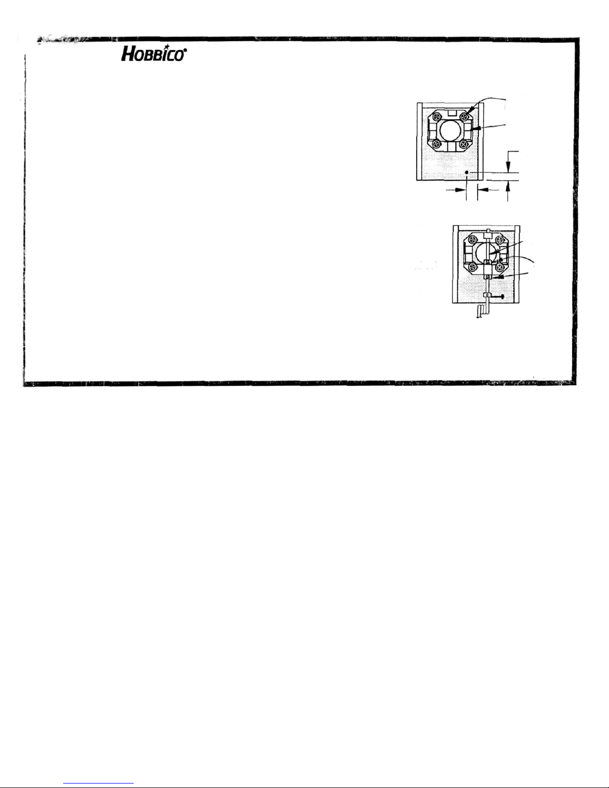
1. On page 16, at step 31, drill a hole in the firewall so it is 9/16" in from the right side and
3/8" up from the bottom as shown in the sketch at right.
3/8"
2. On page 17, before step 35, install the engine mount halves by fitting them together and
attaching them to the firewall using four 6-32 x 3/4" machine screws with washers. Do
not tighten completely until later.
9/16"
3. On page 17, at step 36, install the nose gear strut through the steering arm, followed by a 4mm
collar. Next, slide the strut through the lower lug on the engine mount and install a second collar
(see sketch at right). Tighten the collars using 3 x 5mm machine screws.
Nose gear
strut
4. On page 17, at step 37, rotate the steering arm so it is 1/2" away from the firewall with the wheel
pointing straight ahead.
4mm
Collars
5. On page 18, after step 46, once the engine in properly positioned, tighten the engine mount to
the firewall.
6. On page 19, step 47, drill four 7/64" holes at the marks. Do not drill 1/8" holes.
7. On page 19, step 50 will tell you to mount the engine using four 3 x 25mm machine screws with washers and nuts. This hard
ware has been replaced with four #6 x 3/4" sheet metal screws. Simply screw these into the mount to hold the engine in piace.
AV12ADD2
Page 3
You're about to build in just days what took aviation pioneers years—a powered machine that flies.
Specially created for you and other first-time radio control acrobatic pilots, Hobbico's Avistar 40 offers
nearly all the excitement of piloting a real airplane...and develops skills that will take you anywhere you
want in your new hobby.
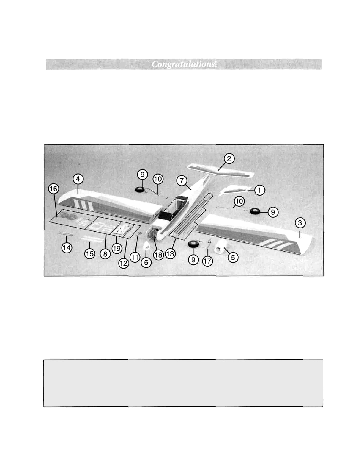
Know Your Model's Parts
Take a moment now to match the box contents with the items listed below. Following the Avistar 40's
assembly instructions will be quite easy if you identify and organize the parts before you begin.
1. RUDDER/FIN (C)
2. STABILIZER/ELEVATOR
(C)
3. LEFT WING PANEL
(A)
4. RIGHT WING PANEL
(A)
5. FUEL TANK (B)
6. SPINNER
(B)
7. FUSELAGE
(B)
8. SERVO TRAY
(B)
9. WHEELS (D)
10.
MAIN LANDING GEAR
(D)
11.
METAL HARDWARE (B)
12.
NYLON HARDWARE
(B)
13.
PUSHRODS (B)
14. WING
DOWELS
(B)
15.
DIHEDRAL BRACES
(A)
16.
HARDWARE (B)
17. NOSE
GEAR
(D)
18. ONE-PIECE ALUMINUM ENGINE MOUNT (B)
19.
BATTERY / RECEIVER TRAY
(B)
Replacement Parts Available
HCAA3030.....Wing Kit (A)
HCAA3031..... Fuselage Kit (B)
HCAA3032.....FinSet(C)
HCAA3033.....Landing Gear Set (D)
() Letter indicates items included in each replacement set.
2
Page 4

Other Items You'll Need
Glues
Choose any 6-minute epoxy, such as Great Planes®
Pro'" Epoxy, which has been formulated especially
for R/C model building. Epoxies offer a strong
bond and a variety of curing times suited for every
step of assembly. You'll also need an instant-setting
CA (cyanoacrylate), a thicker CA+, and a 30-minute
epoxy, plus rubbing alcohol and paper towels for
easy epoxy cleanup.
Hardware
Tools and accessories required for assembly:
Hobby knife Needle nose pliers
#11 knife blades Large Phillips screwdriver
#64 Rubber bands Small Phillips screwdriver
Ruler 3 ft of 3/32" fuel tubing
Drill with drill bits: 1/16", 3/32", and 3/16"
Model Engine
Power your Avistar with any high-quality, .40-size
model engine. The O.S.® .40 LA and SuperTigre®
GS-40 are just a few examples. Look for features
such as easy break-in, easy starting, efficient
carburetion and low maintenance. Check the
manufacturer's recommendations for propellers to
use with your engine.
Radio Equipment
To let you send the commands that control your
Avistar 40's "flight path," you'll need a 4-channel
aircraft radio system with four standard servos.
Many 4-channel radios include just three servos.
You may need to purchase the fourth separately.
The servos and radio receiver will be mounted onboard your model and need to be cushioned from
jolts and vibration. One-half inch thick foam
rubber sheets are available for this purpose.
Getting Ready for Flight
Your Hobbico Avistar 40 trainer is ready for takeoff
in as little as 15-20 hours. Your hobby dealer or
flying instructor can help you decide what
accessories you'll need for flight. Most are one-time
only purchases—and your instructor will probably
allow you to use his field box until you can outfit
your own with a glow plug starter, fuel bulb or
pump, and "chicken stick" or electric starter. You
will need to provide your own fuel. Use glow fuel
with a 10-15% nitro blend to keep your engine
performing at its peak...and your Avistar 40 will
have the power to make you an accomplished pilot!
Other General Items Required:
Masking Tape
Epoxy Brushes
T-Pins
Clothes pins
Sandpaper
Foam Rubber
Mixing Sticks
Felt-Tip Marker
String
Paper Towels
Standard Screwdriver
Thread Locking Compound
Epoxy Mixing Cups Wing Seating Tape
Find A Flying Instructor
The best way to begin flying your Avistar 40 is with
an experienced R/C pilot or flying instructor at
your side. You'll learn faster, relax those in-flight
jitters and avoid risking your model before you're
truly ready to solo.
Where do you find an instructor? Ask at your local
hobby shop. They'll have information about flying
clubs in your area whose membership includes
qualified instructors. You can also join the
Academy of Model Aeronautics (AMA), a 165,000
member-strong national organization with more
than 2,500 chartered clubs across the country.
Through any one of them, instructor training
programs and insured newcomer training are
available. Contact the AMA at the address or phone
number below:
Academy of Model Aeronautics
5151 East Memorial Drive
Muncie, IN 47302
Toll Free: (800) 435-9262
Fax: (765) 741-0057
Web Site: http://www.modelaircraft.org
3
Page 5

Please follow these safety precautions:
Before you fly
1. Make sure that no other flyers are using your
radio frequency.
2. Your radio transmitter must be the FIRST thing
you turn ON, and the LAST thing you turn OFF.
Fuel storage and care
1. Do not smoke near your engine or fuel.
2. Store all engine fuel in a safe, cool, dry place,
away from children and pets.
3. Always wear safety glasses.
4. Make certain that your glow plug clip is securely
attached to the glow plug—and cannot pop off,
possibly falling into the spinning propeller.
5. Use a "chicken stick" or electric starter to start
the engine— NOT your fingers.
6. Make sure that the wires from your starter and
glow plug clip cannot become tangled with the
spinning propeller.
7. Do not stand at the side of the propeller when
you start or run the engine. Even at idle speed,
the spinning propeller will be nearly invisible.
8. If any engine adjustments are necessary,
approach the engine only from behind the
spinning propeller.
90-Day Limited Warranty
If you, as the original owner of this model, discover
defects in parts or workmanship within 90 days of
purchase, Hobbico will repair or replace it—at the
option of our authorized U.S. repair facility, Hobby
Services—without charge. Our liability does not
include cost of shipping to us. However, Hobby
Services will pay shipping expenses to return your
model to you.
You must provide proof of purchase, such as your
original purchase invoice or receipt, for your
model's warranty to be honored.
This warranty does not apply to damage or defects
caused by misuse or improper assembly, service or
shipment. Modifications, alterations or repair by
anyone other than Hobby Services voids this
warranty. We are sorry, but we cannot be
responsible for crash damage and/or resulting loss
of kits, engines, accessories, etc.
Repair Service
Your Avistar 40 must be returned directly to Hobby
Services for warranty work. The address is:
Hobby Services,
Attn: Service Department
1610 Interstate Drive, Champaign, IL 61822
Phone: (217) 398-0007
Please follow the instructions when returning your
model. This will help our experienced technicians
to repair and return it as quickly as possible.
1. ALWAYS return your entire system, including
airplane and radio.
2. Disconnect the receiver battery switch harness
and make sure that the transmitter is turned off.
Disconnect all batteries and drain all fuel.
3. Include a list of all items returned and a
THOROUGH, written explanation of the
problem and service needed. If you expect the
repair to be covered under warranty, also
include your proof of purchase.
4. Include your full return address and a phone
number where you can be reached during the day.
If your model is past the 90-day warranty period or
is excluded from warranty coverage, you can still
receive repair service through Hobby Services at a
nominal cost. Repair charges and postage may be
prepaid or billed COD. Additional postage charges
will be applied for non-warranty returns. All
repairs shipped outside the United States must be
prepaid in U.S. funds only.
All pictures, descriptions and specifications
found in this instruction manual and on the
product package are subject to change without
notice. Hobbico maintains no responsibility for
inadvertent errors.
4
Page 6
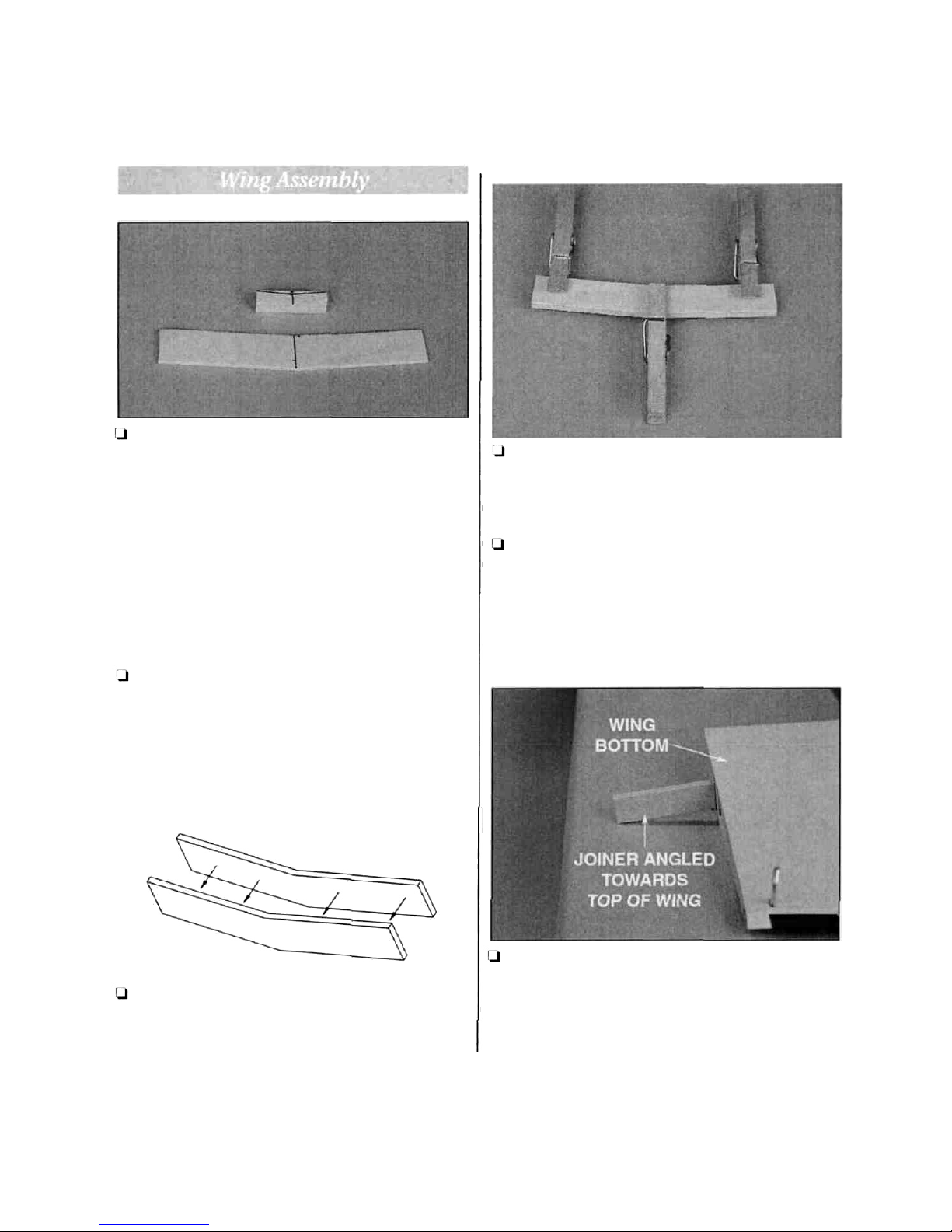
Q Find the two 1/8" (3mm) die-cut plywood wing
joiners. Draw a center line on both sides of the
plywood wing joiners and balsa aileron servo tray
mounting blocks. Use one plywood joiner as a
template to mark the wing dihedral angle on both
of the balsa 5/16" x5/16" x 1-1/2" (8mm x 8mm x
38mm) aileron servo tray mounting blocks. Put
these mounting blocks aside for use later.
Orientation of the wing joiners
Q Arrange the two "V-shaped plywood wing
joiners in the same orientation as they will be
glued together.
Gluing the wing joiner
Q Mix approximately l/4oz. (7.5ml) of30-minute
epoxy. Using a mixing stick or epoxy brush, apply
an even coat of epoxy on one side of a wing joiner.
Stack the other joiner on top of the epoxy.
Clamping the wing joiner
l-l Use three clothes pins to clamp the wing joiners
together firmly. The excess epoxy must be removed
before it cures as described in the next step.
Removing the excess epoxy
l-l Excess epoxy will be squeezed out of the seams
between the joiners and must be removed before
the epoxy is allowed to cure. Use a paper towel and
rubbing alcohol to remove the excess epoxy.
Be careful not to disturb the alignment of the
joiner pieces.
Test fit the wing joiner
After the epoxy has cured and the clothes pins
have been removed, test fit the wing joiner in both
wings by sliding the joiner into the joiner cavity in
the wing. The joiner should slide in with a little
resistance up to the centerline drawn on the both
sides of the joiner.
5
Page 7
Sanding the joiner
Cl If the wing joiner will not Fit in the cavity, lightly
sand the excess epoxy and uneven surface joints
from the joiner edges and sides. Caution: A snug fit
is desirable between the joiner and the wing cavity.
Do not sand excessively.
Viewing the wing dihedral
Cl Pay close attention to the orientation of the wing
joiner in relation to the dihedral of the wings.
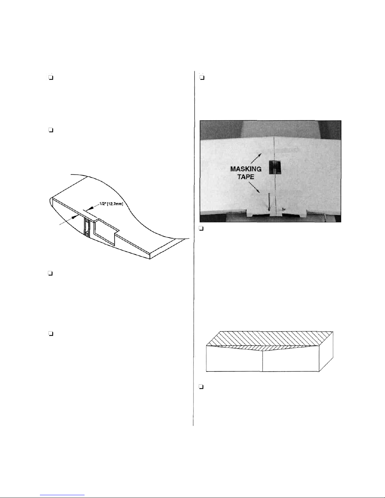
Marking the wing cavity
1-1 Lay the wing halves on the work surface with the
flat side facing up. Remove the precut balsa from the
root rib. Using the measurements in the sketch, trim
away the balsa sheeting from the bottom of the wing
to allow for the installation of the aileron servo.
Gluing the joiner in the wing
1-1 Mix l/4oz. (7.5ml) of 30-minute epoxy to glue
the joiner into one wing half. Use a mixing stick or
epoxy brush to apply epoxy to all four sides of the
joiner cavity wall. Insert the joiner into the cavity
up to the centerline marked on the joiner plate. Be
sure you are installing the joiner in the correct
orientation to the wing. It should angle upwards
when installed correctly. Clean the excess epoxy
from the wing root rib. You must be sure all the
excess glue is removed from the wing root or the
wings will not fit together correctly. Allow enough
time for the epoxy to fully cure before proceeding
to the next step.
Applying the epoxy
l-l Mix l/2oz. (14.5ml) of 30-minute epoxy and
apply to the wing root rib and inside the joiner
cavity of the second wing half.
Joining the wing halves
Q Assemble the two wing halves with the tightest
seam possible. No gaps should be showing between
the two wing halves. Clean the excess epoxy from
the outside of the wing using a paper towel and
rubbing alcohol. Tape the wing halves together with
masking tape. Set the wing aside to cure.
Cutting the mounting blocks
l-l Find the aileron servo tray and the two balsa
servo tray mounting blocks and position them
with the marked dihedral line up. Using a sharp
hobby knife, cut the angle out of the block. This
angle will be placed against the wing when the
servo tray is installed.
6
Page 8
Assembling the servo tray
Q Apply thick CA+ to the flat side of the balsa servo
tray mounting block. Place the mounting block on
the aileron servo tray next to the servo
opening-not on the outer edge of the tray. Note the
positioning of the dihedral angle in relation to the
servo tray.
Q Test fit the aileron servo into the servo tray and
the hole cut in the bottom side of the wing. Enlarge
either hole, if needed, with a hobby knife or a finetoothed file until a proper fit is achieved.
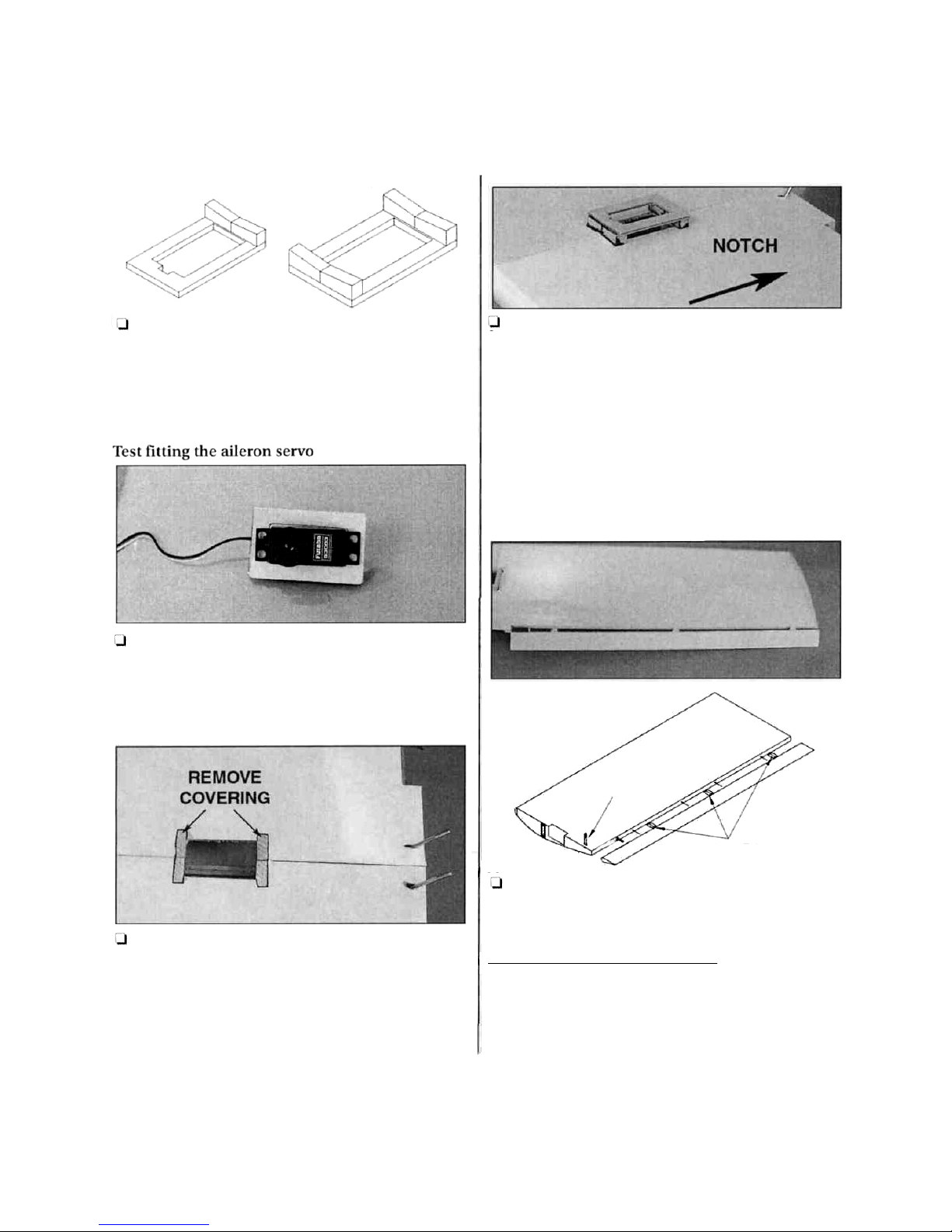
Removing the covering
Q Position the aileron servo tray so it is centered
over the opening made in the wing. Using a felt-tip
marker, trace the outside of the servo tray
mounting block onto the wing. Use a sharp hobby
knife to remove the covering for the mounting
blocks. Use care not to cut into the underlying
balsa of the wing, as this may weaken the wing.
Installing the servo tray
J Mix l/8oz. (3.5ml) of 6-minute epoxy to glue the
servo tray to the bottom side of the wing. Apply
equal amounts of epoxy to the mounting blocks on
both ends of the servo tray. Attach the servo tray on
the bottom of the wing with the servo wire harness
notch facing the trailing edge of the wing. The
mounting blocks should be attached to the wing
sheeting where the covering was removed and not
to the plastic wing covering. Allow the epoxy to
fully cure before proceeding to the next step.
Aileron installation
HINGES
TORQUE
ROD
l-l Test fit the ailerons on the wing with the hinges
installed. Check for free movement in both
directions. There should be no binding. Use a
toothpick to push 30-minute epoxy down the
torque-rod holes in each aileron. Fit the aileron in
place. There should Be virtually no gap when the
aileron is fully seated. If the aileron will not fully
seat, use a hobby knife to clean the hinge slots and
try it again. Glue in the hinges by wicking 4 drops
of thin CA into each side of the hinges.
7
Page 9

Page 10

Installing the servo tray Constructing the tail section
Mix l/8oz. (3.5ml) of 6-minute epoxy to glue the
servo tray into the fuselage. Apply epoxy to all
fuselage parts that will come in contact with the
servo tray.
Q Locate the horizontal stabilizer slot under the
covering on the tail section of the fuselage by
pressing lightly with your finger. The slot will be
located on both sides of the tail. Using a hobby
knife, carefully remove the covering exposing the
slots. Note: Do not cut into the balsa wood
sheeting around the slot.
Installing the wing dowels
LI The wing dowel holes are predrilled. Locate the
four round holes (two on each side of the fuselage)
and remove the covering over each hole. Insert the
two wood dowels into the fuselage. The shorter
dowel is installed towards the tail of the airplane.
Install the dowel caps onto the dowels using four
2.5mm x 8mm sheet metal screws. You may need to
hold one screw with a pliers while installing the
other side.
Vertical stabilizer slot covering
Q Using your finger, locate the vertical stabilizer
slot on the top of the fuselage. Remove the
covering with a hobby knife in the same manner as
for the horizontal stabilizer slots. This will allow
better viewing access when centering the
horizontal stabilizer.
Finding the centerline
A
A
Q Locate the horizontal stabilizer and draw a
centerline on the side with the three color graphics.
Insert the stabilizer into the tail section with the line
showing through the vertical stabilizer slot.
9
Page 11

Preparing to install the stabilizer
EQUAL MEASUREMENTS
Q Attach a piece of string with a pin to the center of
the firewall as shown. The string should be a
minimum of 31-1/2" (800mm) in length. Stretch
the string to the corner of the horizontal stabilizer.
The distance from the pin to the horizontal
stabilizer must be the same on both sides. This
method will adjust the horizontal stabilizer to a
90" angle to the centerline of the aircraft.
Tracing the fuselage outline
U Using a felt-tip pen, trace a line around the tail of
the airplane on the top and bottom of the
horizontal stabilizer.
Removing the covering
Q Using a sharp hobby knife, cut 1/32" [1mm]
inside the lines made with the felt-tip pen and
remove the covering from the center of the
horizontal stabilizer. Do not cut into the balsa
sheeting on the horizontal stabilizer.
Installing the stabilizer
Q Mix l/4oz. (7.5ml) of30-minute epoxy to install
the horizontal stabilizer. Using a mixing stick,
place glue inside the horizontal stabilizer slot on
all sides including the horizontal stabilizer mount.
Insert the horizontal stabilizer and clean off the
excess epoxy that squeezes out of the joint with a
paper towel and rubbing alcohol. Adjust alignment
as shown in the previous step. Set the fuselage
aside to cure.
Preparing the vertical stabilizer
Q Locate the vertical stabilizer. Draw a line on both
sides even with the bottom of the fin as shown in
the sketch. Cutting 1/32" (1mm) below the line and
through the covering only, remove the covering
from the base of the vertical fin.
Important: Do not cut into the balsa fin root.
T-PIN
STRING
STRING
10
Page 12

Installing the vertical stabilizer
90°
90°
Fin
Alignment 90°
Sketch
Q Mix l/4oz. (7.5ml) of 30-minute epoxy to glue
the vertical stabilizer in place. Using a mixing stick,
apply epoxy to the top of the horizontal stabilizer
through the vertical stabilizer slot. Apply epoxy to
the sides and bottom surfaces of the fin base that
have balsa wood exposed. Insert the vertical
stabilizer into the slot, making sure the fin root is
seated firmly on the horizontal stabilizer. Check for
a perpendicular angle between the fin and the
stabilizer when viewed from the back. It is critical
that the fin remains perpendicular while the epoxy
is curing. Masking tape may be required to hold
the fin during this time.
Installing the rudder and elevator hinges
Q Test fit the rudder and elevator on the fin and
stabilizer with the hinges installed. Use the sketch
in "Installing the Ailerons" as a guide. Check for
free movement in both directions. There should be
no binding. Glue in the hinges by wicking 4 drops
of thin CA into each side of the hinges.
Locations of the control horns
l-l Note the locations and alignment of the control
horns in both the photo and the illustration before
marking and drilling.
Control horn alignment
HINGE LINE
CORRECT INCORRECT
11
Page 13

Attaching the elevator control horn
Locating the rudder exit hole
Locate a nylon control horn. Place the horn on
the bottom of the elevator. Position it 1" (25.4mm)
from center and aligned with the leading edge as
shown in the sketch and photo. Mark the two holes
with a felt-tip pen. The holes of the control horn
should line-up with the gap between the rudder
and the vertical stabilizer. Drill two 1/16" (1.5mm)
holes through the balsa elevator. Insert two 2-56 x
5/8" machine screws through the control horn and
elevator into the control horn back plate on the
opposite side of the elevator. Tighten the screws
but do not crush the balsa.
QThe precut rudder pushrod exit hole is located on
the same side as the rudder control horn, under the
covering. Locate the exit hole by gently running
your finger down the top of the fuselage. Using a
hobby knife, remove the covering from the rudder
pushrod exit hole. Do not remove the covering from
the exit hole on the opposite side.
Cutting the elevator exit hole
Installing the rudder horn
Locate the other nylon control horn. Place the
control horn on the left side of the rudder, 1" (25mm)
from the top of the hinged stabilizer as shown in the
photo on the previous page. Mark the two holes with
a felt-tip pen. Drill two 1/16" (1.5mm) holes through
the rudder. Use two machine screws 2-56 x 5/8" to
attach the control horn.
Q The precut elevator pushrod exit hole is located
on the same side of the fuselage as the elevator
control horn, beneath the covering. Locate the exit
hole by gently running your finger down the side of
the fuselage over the covering. Using a hobby knife,
remove the covering from the elevator pushrod
exit hole. Do not remove the covering from the exit
hole on the opposite side of the fuselage.
12
Page 14

Installing the landing gear
Q On the bottom of the fuselage, 9-3/4" (248mm)
from the engine compartment, there is a channel
located under the covering. Locate this channel by
running your finger over the covering on the bottom
of the fuselage. Using a hobby knife remove the
covering from this channel. To protect the channel
from fuel damage, place several drops of thin CA
along the channel and wipe with a paper towel.
Installing the struts
Q Locate the two chromed landing struts and place
them in the pre-drilled holes inside the channel on
the bottom side of the fuselage. Place two nylon
landing gear straps over the landing gear struts. Using
a felt-tip pen, mark the location of the strap
mounting holes onto the bottom of the fuselage. Drill
the four holes using a 1/16" (1.5mm) drill bit. Mount
the nylon landing gear straps using four #2x3/8" selftapping screws to the bottom of the fuselage over the
struts. The struts should be flush with the bottom of
the fuselage.
Mounting the wheels
Q Locate two foam wheels and four wheel collars.
Place one wheel collar on each strut and secure its
location using a 6-32 set screw. Place the wheel onto
the strut, followed by another wheel collar. Secure the
additional wheel collar with another 6-32 set screw.
In total, you will have two wheel collars, two 6-32 set
screws and one wheel on each strut.
Q Locate the aluminum engine mount and attach
it to the firewall using four 6-32 x 3/4" machine
screws and four #6 washers. The flat side of the
engine mount will be towards the top of the
fuselage as shown in the drawing and photo. Use
thread locking compound on the screws to make
sure they won't vibrate loose. Attach the nose gear
mount to the firewall using two 6-32 x 3/4"
machine screws.
Installing the nose gear
1-1 Place a wheel collar onto the nose gear strut.
Insert the nose gear stem into the plastic nose gear
13
Page 15

holding bracket on the fuselage firewall. Press a
5/32" wheel collar into the nylon steering arm.
Make sure the hole in the arm lines up with the
hole in the wheel collar. Place the nylon steering
arm between the plastic bracket and motor mount.
Slide the nose gear stem into the motor mount.
Lock the steering arm onto the flat spot of the nose
gear by tightening the socket head screw on the
front of the arm. Insert a 14-1/8" (359mm) pushrod
tube through the hole into the fuselage. The
pushrod tube must be flush with the firewall for
the steering to work properly. Wick thin CA around
the pushrod guide tube.
Installing the pushrod
Q Locate the 17-1/2" (445mm) wire control rod (no
threads) and make a 90-degree bend in one end
1/2" from the end. Remove the steering arm from
the nose gear assembly. Insert the bend into the
inside hole of the steering control horn from the
bottom. Slide the pushrod wire into the guide tube
and reassemble the nose gear assembly. Trim the
remaining arm to allow for maximum steering.
Throttle control guide
Q Insert the remaining plastic pushrod guide tube
into the predrilled hole in the engine compartment
firewall. Leaving 1/4" (6mm) of the tube showing,
glue the throttle control tube into the firewall using
thin CA.
Insert the control rod
Q Install a 14-1/8" (360mm) pushrod tube into the
firewall for the throttle pushrod. Leave 1" (25mm) of
the pushrod tube to extend forward of the firewall.
Secure the pushrod tube using thin CA. Thread a
clevis onto the 17-1/2" (440mm) pushrod using the
same technique as the aileron pushrods. Insert the
pushrod into the tube as shown in the photo.
l-l Locate the two aluminum tubes that are used in
the fuel tank.
Bending the pressure line
Q Being careful not to kink the tube, bend one end
of the longer tube to a 70 degree angle. It may be
helpful to find a rigid object that can be used as a
form to bend the tube around. Leave 1-1/2"
(38mm) of straight tube at one end so it can easily
be inserted through the tank plug.
14
Page 16

Assembling the tank plug Installing the tank
U Locate the two stopper plates. Push the aluminum
tubes through the smaller stopper disc and the back
of the rubber plug. Place the larger stopper disc on
the opposite side and insert the 3 x 20mm machine
screw through the larger disc, the rubber plug and
then into the smaller disc. Do not tighten the screw
at this time.
Final fuel tank assembly
Q Locate the metal fuel pick-up weight (often
referred to as the "clunk weight") and the medium
silicone fuel tubing. Insert the fuel pick-up weight
onto the fuel tubing. Compare the length of the
fuel tank to the length of the fuel tubing and cut
the tubing so that the fuel pick-up weight on the
end of the fuel tubing will not touch the end of the
fuel tank. The plug assembly can now be inserted
into the tank. The pressure tube should be
adjusted so the tube is pointed straight up just
under the top of the tank.
Caution: The pressure tube should be close but not
touching the top of the tank because the flow of fuel
may be interrupted and cause the engine to quit.
The stopper discs on the rubber plug can be
tightened by turning the screw. Do not over tighten
the stopper plates or damage to the tank may occur.
(-1 Insert the fuel tank into the fuselage as shown in
the photo.
Orientation of the fuel ports
1-1 Note the locations of the fuel tubes. Cut two fuel
line lengths, pressure line 4-1/2" (114mm) and fuel
line 4" (101mm), from medium silicone fuel line
(not included). Place the cut fuel lines over the
correct tubes.
Mounting the engine
1-1 The photo shows an O.S. 40 LA engine mounted.
Secure the engine by using two engine mounting
15
Page 17

brackets, four 4 x 15mm screws, four 4mm lock
washers and four 4mm nuts. The engine centerline
must be in line with the fuselage centerline. Place
the engine on the mount and secure the engine with
the engine brackets. The lock washers should be
located on top of the bracket under the head of the
screw. The screws are secured by four 4mm nuts.
Note: Thread locking compound is recommended
for use on the engine mounting screws. Attach the
clevis to the throttle arm in the hole closest to the
center of the arm.
Attaching the muffler
Q Locate the muffler and mount it to the engine by
using the screws included with the engine. The
exhaust outlet should be pointing down and away
from the fuselage. Use the instructions included
with the engine to make this adjustment.
Running the fuel line
Q Run the fuel lines to the proper locations on the
engine (fuel line to the fuel inlet, pressure line to
the muffler).
Mounting the propeller and spinner
Q Slide the spinner backplate onto the crankshaft of
the engine. Align the propeller with the two alignment
pegs on the backplate. Secure the propeller and
backplate to the engine using the washer and nut
included with the engine. Use a wrench to tighten the
nut. If the nut is even slightly loose, the propeller
could come off and become a hazard.
Final spinner assembly
Q Place the spinner cone onto the backplate until
they snap together. They must be aligned correctly
for a proper fit. The spinner cone must not come in
contact with the prop or fatigue and fracture of the
prop may occur over a period of time. Insert both
2 x 12mm self-tapping screws into the spinner and
tighten firmly,
Radio Installation
Installing the receiver and battery
Q Wrap both the receiver and battery pack in foam
rubber (not included). Using the supplied hook and
loop material, attach the receiver and battery pack
to the radio gear tray using the photo as a guide.
Alignment Pegs
Alignment Pegs
16
Page 18

Installing the switch
Q Cut a rectangular switch hole in the side of the
fuselage opposite the exhaust using a hobby knife.
Locate the receiver switch harness in the radio
system and remove the face plate. Place the switch
into the hole with the switch facing outward. Put
the face plate over the switch and mark the screw
holes with a felt-tip marker using the plate as a
template. Drill the screw mounting holes using a
1/16" (1.5mm) drill bit. Install the switch from the
inside of the fuselage with the "on" position toward
the rear of the plane. If the switch should get hit
while the plane is moving forward, it would not
turn the receiver off. Secure the switch using the
two screws supplied with the switch.
Preparing the servos
Q Remove the servo arms and wheels from the three
servos. Install the rubber grommets that came with
the radio system onto the servos, following the
instructions included with your radio system.
Servo installation
1-1 Install the three servos from your radio system as
shown in the photo. Refer to the radio manufacturer's
manual for more detailed instructions. Notice the
location and orientation of each servo as well as the
switch location.
Antenna Routing
STRAIN RELIEF
INSIDE FUSELAGE
ANTENNA HOLDER
AT
THE
TOP
OF
THE
VERTICAL STABILIZER
CUT
CUT
RUBBER
BAND
Q Drill a 1/16" (1.5mm) exit hole in the center of the
rear window 1" (25.4mm) down from the edge of the
radio compartment. Route the antenna under the
plywood servo tray and up through the exit hole. Do
not cut the antenna wire. The receiver is tuned to a
specific length of antenna. Use a medium T-pin to
attach a rubber band to the top portion of the
vertical stabilizer. Tie the antenna to the rubber
band using tension to keep the antenna tight. Use
caution not to damage the antenna. A servo horn
can be cut and used to hold the antenna in place at
both ends with less likelihood of damage to the
antenna wire.
Q Locate the two 21-3/4" (555mm) outer pushrod
tubes. Slide the tubes into the fuselage from the
elevator and rudder pushrod exits. Enlarge the
exits to allow the tubes to slide in easily. Don't glue
the tubes at this time.
Q Center the ailerons, then mark the pushrods at
the point where they meet the holes in the servo
arm. Make a 90 degree bend down in the wires at
this mark.
T-PIN
17
Page 19

Q Cut off the excess wire 3/8" (9.5mm) above the
bend. Enlarge the servo horn holes with a 5/64"
(2mm) drill bit. Insert the bent wire pushrods into
the servo horn from the upper side, then secure
them with Nylon FasLink Pushrod Keepers.
Q Thread clevises onto the 26-3/4" (680mm)
pushrods using the same technique as the aileron
pushrods. Insert the pushrods into the rudder and
elevator pushrod tubes as shown in the photo.
Attach the clevises for both the elevator and rudder
to the control horns as shown. (Both clevises are
attached in the same locations.)
Q
0 Center the elevator, then mark the pushrod
where it crosses the servo horn hole. Enlarge the
servo horn hole with a 5/64" (2mm) drill bit. Make
a 90 degree bend in the pushrod at the mark (you
may want to disconnect the clevis from the elevator
control horn to pull the pushrod wire out of the
fuselage to make it easier to bend). Cut off the
excess wire 3/8" (9.5mm) above the bend. Insert the
bent wire through the enlarged hole in the servo
horn. Secure it in place with a nylon FasLink.
Q Repeat the above step for the rudder pushrod.
1-1 Adjust the height of the pushrod support so the
pushrods can move freely without binding. Glue the
brace into position using medium CA. Slide the
pushrod tubes so 1/8" (3mm) extends forward of
the pushrod support. Glue the pushrod tubes to the
brace using thin CA. Be very careful not to get CA
into the tubes and accidentally glue the pushrod
wires to the tubes. Glue the pushrod tubes to the
fuselage using medium CA.
l-l With the radio on, move the throttle trim lever
and control stick to the closed position, by pulling
them back (or downward) all the way. Manually
close the throttle on the carburetor completely.
Tighten the set screw on the pushrod connector.
Check throttle operation with the radio and make
adjustments to the linkage as necessary for smooth
operation from fully closed to fully open. Use the
appropriate holes in the servo horn and throttle
arm to provide the correct amount of throttle
movement and to prevent the servo from binding
at its end points.
Q Install the nose wheel using the same technique
as the main wheels. Center the nose wheel and
tighten the screw on the pushrod connector for the
nose wheel steering.
18
Page 20

NOTE: This section is VERY important and must
NOT be omitted! A model that is not properly
balanced will be unstable and possibly unflyable.
Q Use a felt tip pen or a narrow strip of tape to
accurately mark the balance point on the bottom of
the wing near both sides of the fuselage. The
balance point (CG) on the Avistar 40 is located
3-1/4" (83mm) back from the leading edge. This is
the point at which your model should balance for
your first flights. Later, you may experiment by
shifting the balance up to 5/16" (8mm) forward or
back to change the flying characteristics. Moving
the balance forward may improve the smoothness
and arrow-like tracking, but it may require more
speed for takeoff and make it more difficult to slow
down for landing. Moving the balance aft makes the
model more agile with a lighter and snappier feel.
Please start at the location we recommend and do
not at any time balance your model outside the
recommended range.
Plug the aileron servo into the receiver. Mount the
wing to the fuselage with #64 rubber bands. The
engine, muffler, propeller and fuel tank should also
be mounted for the C.G. check.
With the fuel tank empty and the wing attached to
the fuselage, lift the model with your finger tips at
the balance point. If the tail drops when you lift,
the model is "tail heavy" and you must move the
battery and/or the receiver toward the nose to
achieve balance. If the nose drops, it's "nose heavy"
and you must move the battery and/or receiver
toward the tail to achieve balance. The C.G. is
always determined with the fuel tank empty.
Balance the model by shifting the receiver battery
and receiver, then test again. When balance is
obtained note the position of the of the receiver,
and the battery pack. If the balance cannot be
achieved by positioning the battery and receiver,
you may add stick-on lead weight to the tail or
nose if required.
Confirm that the battery and receiver are securely
wrapped in foam and secured so they cannot shift
during flight or a rough landing.
IMPORTANT: After the model is 100% complete,
recheck the balance.
IMPORTANT: Go back and check your installation.
Be sure that all servo screws, horns and other
components are secure. Confirm that you have
installed the retainers on the screw lock connectors.
Apply a strip of 1/16" (1.5mm) thick foam wing-
seating tape (not included) to the wing saddle.
This tape provides a seal against dirt and exhaust
oil and cushions the wing from vibration.
4-CHANNEL RADIO SETUP
(STANDARD MODE 2)
ELEVATOR MOVES UP
RIGHT AILERON MOVES UP
LEFT AILERON MOVES DOWN
RUDDER MOVES RIGHT
CARBURETOR WIDE OPEN
Q Check the direction of all control functions. They
must all move in the direction shown in the sketch.
If not, change the position of the reversing
switches on your transmitter.
3-1/4" (83mm)
19
Page 21

Control Surface Throws
We recommend the following throws:
NOTE: Control throw (movement) is measured
at the trailing edge of the elevator, rudder and
ailerons. Hold a ruler vertically on your
workbench or block it up on books to make
these measurements.
ELEVATOR: 3/8" up
3/8" down
RUDDER:
3/4" right 3/4" left
AILERONS: 5/16" up 5/16" down
NOTE: The balance and control throws for the
Avistar 40 have been thoroughly tested and
represent the settings at which the Avistar 40
flies best. Please set up your Avistar 40 to the
specifications listed. If, after a few flights, you
would like to adjust the throws to suit your
taste, that's fine. Remember, "more is not better."
Note: If your radio system does not feature
Adjustable Travel Volume (ATV's), you will have to
mechanically adjust control surface throw.
Q Control throw adjustment: If you move the clevis
at the control horn on the control surface toward
the outermost hole, you will decrease the amount
of throw. If you move the clevis to a hole nearer the
control surface you will increase the amount of
throw. If these adjustments do not provide the
desired throws, you may need to work with a
combination of adjustments by repositioning the
pushrod at the servo. If you move the pushrod
toward the splined shaft on the servo arm, it will
decrease the control surface throw - outward will
increase it.
Ground Stance
NOSE
TOO HIGH
NOSE
TOO LOW
LEVEL
Q "Eyeball" the side of the fuselage from 6 - 10 feet
away. If necessary adjust the height of the nose by
raising or lowering the nose gear wire so that your
model will sit pretty much level, as shown in
the sketches.
Once the correct ground stance is established,
tighten the screws on both the steering arm and
wheel collar on the flat spot of the nose gear wire to
lock the nose gear strut in position. Use thread lock
on both screws.
It is a good practice to periodically check the ground
stance of your Avistar 40 - especially after a hard
landing. The wire landing gear is designed to absorb
shock from rough landings but occasionally may
need to be bent back into position.
Charge the Batteries
Follow the battery charging procedures in your
radio instruction manual. You should always
charge your transmitter and receiver batteries the
night before you go flying and at other times as
recommended by the radio manufacturer.
Balance the Propeller
Balance your propellers carefully before flying. An
unbalanced prop is the single most significant
cause of vibration. Not only will engine mounting
screws and bolts vibrate out, possibly with
disastrous effect, but vibration will also damage
your radio receiver and battery. Vibration will
cause your fuel to foam, which will, in turn, cause
your engine to run lean or quit.
We use a Top Flite' Precision Magnetic Prop
Balancer'" (#TOPQ5700) in the workshop and keep
a Great Planes Fingertip Balancer" (#GPMQ5000)
in our flight box.
20
Page 22

Find a Safe Place to Fly
The best place to fly your R/C model is an AMA
(Academy of Model Aeronautics) chartered club
field. Ask your hobby shop dealer if there is such a
club in your area and join. Club fields are set up for
R/C flying and that makes your outing safer and
more enjoyable. The AMA also can tell you the
name of a club in your area. We recommend that
you join AMA and a local club so you can have a
safe place to fly and have insurance to cover you in
case of a flying accident (The AMA address is listed
on page 3 of this instruction book).
If a club and its flying site are not available, you
need to find a large, grassy area at least 6 miles
away from any other R/C radio operation like R/C
boats and R/C cars and away from houses,
buildings and streets. A schoolyard may look
inviting but it is too close to people, power lines
and possible radio interference.
Ground Check the Model
If you are not thoroughly familiar with the
operation of R/C models, ask an experienced
modeler to check that you have installed the radio
correctly and all the control surfaces do what they
are supposed to. The engine operation also must
be checked and the engine "broken-in" on the
ground by running the engine for at least two tanks
of fuel. Follow the engine manufacturer's
recommendations for break-in. Check to make
sure all screws remain tight, that the hinges are
secure and that the prop is on tight.
Range Check Your Radio
Whenever you go to the flying field, you need to
check the operational range of the radio before the
first flight of the day. First, make sure no one else is
on your frequency (channel). With your transmitter
antenna collapsed and the receiver and transmitter
on, you should be able to walk at least 100 feet away
from the model and still have control. Have a friend
stand by your model and, while you work the
controls, tell you what the control surfaces are
doing. Repeat this test with the engine running at
various speeds with a helper holding the model. If
the control surfaces are not always acting correctly,
do not fly! Find and correct the problem first. Look
for loose servo connections or corrosion, loose
bolts that may cause vibration, a defective on/off
switch, low battery voltage or a defective cell, a
damaged receiver antenna, or a receiver crystal that
may have been damaged from a previous crash.
Engine Safety Precautions
NOTE: Failure to follow these safety precautions
may result in severe injury to yourself and others.
Keep all engine fuel in a safe place, away from high
heat, sparks or flames as fuel is very flammable. Do
not smoke near the engine or fuel; and remember
that the engine exhaust gives off a great deal of
deadly carbon monoxide. Do not run the engine in
a closed room or garage.
Get help from an experienced pilot when learning
to operate engines.
Use safety glasses when starting or running engines
and make all engine adjustments from behind the
rotating propeller.
Do not run the engine in an area of loose gravel or
sand; the propeller may throw such material in
your face or eyes.
Keep your face and body as well as all spectators
away from the plane of rotation of the propeller as
you start and run the engine.
Keep items such as these away from the prop:
loose clothing, shirt sleeves, ties, scarfs, long hair
or loose objects such as pencils, screw drivers that
may fall out of shirt or jacket pockets into the prop.
Use a "chicken stick" device or electric starter;
follow instructions supplied with the starter or
stick. Make certain the glow plug clip or connector
is secure so that it will not pop off or otherwise get
into the running propeller.
The engine gets hot! Do not touch it during or after
operation. Make sure fuel lines are in good
condition so fuel will not leak onto a hot engine
causing a fire.
21
Page 23

Page 24

Page 25

Your first flights should consist of mostly straight
and level flight with gentle turns to keep the model
over the field. These flights will give you practice at
coordinating your control inputs and maintaining
the proper orientation of the airplane. As
mentioned earlier, turns are accomplished by
banking the aircraft with the ailerons, then gently
adding some back stick (up elevator). Enough back
stick should be held in to keep the aircraft at a
constant altitude. To stop turning, apply opposite
aileron (or rudder) to level the wings, then release
the sticks. There is a memory aid that may help
keep you out of trouble when the plane is flying
toward you - "put the stick under the low wing." In
other words, move the stick in the direction of the
low wing to raise that wing. When you are
comfortable flying the aircraft, you can practice
using the rudder along with the ailerons to
"coordinate" the turns - usually, a small amount of
rudder applied in the direction of the turn will
keep the tail following in the exact same track as
the nose.
The most common mistake when learning to fly is
"over control." Think of pressure instead of large
movements of the control sticks. Remember all
Avistar 40's will recover from almost any over
control situation within 50 - 100 feet if you simply
let go of the sticks.
Add and practice one maneuver at a time, learning
how your Avistar 40 behaves in each maneuver.
After you have several flights on your Avistar 40, it's
time to reward yourself with your first acrobatic
maneuver - a
loop.
Climb to a safe altitude and
turn into the wind. Apply full throttle, level the
wings, then slowly pull back on the elevator stick to
about 1/2 to 3/4 up elevator (depending on your
throws) and hold this control input. After you go
over the top and start down the back side of the
loop, pull the throttle back to about half. This will
keep the stresses on the airplane low and the
airspeed relatively constant. Keep holding "up"
elevator until the plane is level, then slowly release
the sticks. You're done! It's really that easy!
CAUTION (THIS APPLIES TO ALL R/C
AIRPLANES): If, while flying, you notice any
unusual sounds, such as a low-pitched "buzz",
this may indicate control surface "flutter".
Because flutter can quickly destroy components
of your airplane, any time you detect flutter you
must immediately cut the throttle and land the
airplane! Check all servo grommets for
deterioration (this will indicate which surface
fluttered) and make sure all pushrod linkages
are slop-free. If it fluttered once, it will probably
flutter again under similar circumstances unless
you can eliminate the slop or flexing in the
linkages. Here are some things which can result
in flutter: Excessive hinge gap; Not mounting
control horns solidly; Sloppy fit of clevis pin in
horn; Elasticity present in flexible plastic
pushrods; Side-play of pushrod in guide tube
caused by tight bends; Sloppy fit of Z-bend in
servo arm; Insufficient glue used when gluing in
the elevator joiner wire or aileron torque rod;
Excessive flexing of aileron, caused by using too
soft balsa aileron; Excessive "play" or "backlash"
in servo gears; and Insecure servo mounting.
Landing
When it's time to land, fly a normal landing
pattern and approach as follows: Reduce the
power to about 1/4 and fly a downwind leg far
enough out from the runway to allow you to make
a gentle 180 degree turn. As you make the turn into
the wind for your final approach, pull the throttle
back to idle. The Avistar 40 has a lot of lift so you
will need a slow, reliable idle in order to achieve
a nice, slow landing. Allow the plane to keep
descending on a gradual glide slope until you are
about 3 feet off the runway. Gradually apply a little
up elevator to flare for landing. You should apply
just enough up elevator to hold the plane just off
the runway while the excess speed bleeds off. The
Avistar 40 should settle onto the runway for a slow,
slightly nose-high landing.
Good luck and have fun flying your Avistar 40, but
always stay in control and fly in a safe manner.
 Loading...