

Page 1

INSTRUCTION
MANUAL
WARNING
Please read and understand this manual, the operation and all safety aspects
required for the safe operation of the product. Before use, if you feel that this
product is not for you, please return it to the place of purchase.
Manual Specications and Description Changes
The instruction manual, warranties, and other associated documentation are
subject to change without notice. Hobbico assumes no responsibility for
inadvertent errors to this manual.
© 2016 RISE, a Hobbico company. RISE0200/05
™
Page 2

INTRODUCTION
Thank you for purchasing the VUSION FPV RACER. We want the time you spend
with your new R/C quadcopter to be fun and successful so please read the entire
manual before beginning setup. If for any reason you think this R/C model is not
for you, return it to the dealer immediately. Your dealer cannot accept returns on
any model after final assembly.
For the latest technical updates or manual corrections for the VUSION FPV RACER
please visit the Rise web site at www.explore-rise.com . If there is any new technical
information, changes or important updates to this model, a “tech notice” box will
appear on the page. Click the “tech notice” box to learn more.
SAFETY PRECAUTIONS
Failure to follow these safety precautions
may result in injury to yourself and others.
● Keep your face and body as well as all spectators away from the rotating plane
of the blades whenever the battery is connected. Keep loose clothing, shirt
sleeves, ties, scarfs, long hair or loose objects such as pencils or screwdrivers
that may fall out of shirt or jacket pockets away from the rotors. The spinning
blades of a model quadcopter can cause serious injury. When choosing a
flying site for your VUSION FPV RACER, stay clear of buildings, trees and power
lines. AVOID flying in or near crowded areas. DO NOT fly close to people or
pets. Maintain a safe distance from the quadcopter.
● Your VUSION FPV RACER should not be considered a toy. Because of its
performance capabilities, the VUSION FPV RACER, if not operated correctly,
could cause injury to you or spectators and damage to property.
● DO NOT alter or modif y the model. Doing so may result in an unsafe or unflyable
model.
● When and if repairs are necessary you must correctly install all components so
that the model operates properly on the ground and in the air. Please check
the operation of the model before every ight to insure that all equipment is
operating and that the model has remained structurally sound. Be sure to check
connectors and the propellers before each ight. Replace them if they show
any signs of wear or fatigue.
KNOW BEFORE YOU FLY
As a new owner of an unmanned aircraft system (UAS), you are responsible for
the operation of this vehicle and the safety of those around you. Please contact
your local authorities to find out the latest rules and regulations.
knowbeforeyouy.org
2
faa.gov/uas
Page 3

AMA
We urge you to join the AMA (Academy of Model Aeronautics) and a local R/C
club. The AMA is the governing body of model aviation and membership is
required to fly at AMA clubs. Though joining the AMA provides many benefits,
one of the primary reasons to join is liability protection. Coverage is not limited
to flying at contests or on the club field. It even applies to flying at public
demonstrations and air shows. Failure to comply with the Safety Code may
endanger insurance coverage. Additionally, training programs and instructors are
available at AMA club sites to help you get started the right way. There are over
2,500 AMA chartered clubs across the country. Contact the AMA at the address
or toll-free phone number that follows.
Academy of Model Aeronautics
5151 Eas t Memorial Drive
Muncie, IN 47302-9252
Tele. (800) 435-9262
Fax (765) 741-0057
Or via the Internet at: www.modelaircraft.org
IMPORTANT: Two of the most important things you can do to preserve the radio
controlled aircraft hobby are to avoid flying near full-scale aircraft and avoid
flying near or over groups of people.
BATTERY WARNINGS
● ALWAYS unplug your battery from either the charger or quadcopter after use.
NEVER store your quadcopter with the battery plugged into the quadcopter.
● DO NOT attempt to charge your battery if it becomes swollen or hot.
● The VUSION FPV RACER does not have a voltage cutoff/failsafe. When the
alarm sounds, land the quad and disconnect the battery.
● It is best to store your batteries in a cool, dry location at 1/2 charge (11.4V).
Storing a fully discharged battery may cause irreversible damage to the battery.
● NEVER disassemble, puncture or modify the battery pack in any way.
● NEVER allow the battery temperature to exceed 150° F [65° C].
● If your batter y begins to swell or “puff” during charge or discharge or becomes
damaged in any way, stop using it.
WARRANTY
RISE™ guarantees this kit to be free from defects in both material and workmanship
at the date of purchase. This warranty does not cover any component parts
damaged by use or modification. In no case shall RISE’s liability exceed the original
cost of the purchased kit. Further, RISE reserves the right to change or modify this
warranty without notice. In that RISE has no control over the final assembly or
3
Page 4

material used for final assembly, no liability shall be assumed nor accepted for
any damage resulting from the use by the user of the final user-assembled product.
By the act of using the user-assembled product, the user accepts all resulting
liability. If the buyer is not prepared to accept the liability associated with the use
of this product, the buyer is advised to return this kit immediately in new and
unused condition to the place of purchase.
To make a warranty claim, send the defective part or item to Hobby Services at
this address.
Hobby Services 217-398 -8970 ext #6
3002 N. Apollo Dr., Suite 1 productsupport@hobbyservices.com
Champaign, IL 61822 USA
Include a letter stating your name, return shipping address, as much contact
information as possible (daytime telephone number, fax number, e-mail address),
a detailed description of the problem and a photocopy of the purchase receipt.
Upon receipt of the package the problem will be evaluated as quickly as possible.
FEATURES
● Entry Level 250 class racing quad
● Oneshot125 speed controls
● 2280kV 1806 size Brushless motors
● Ready to Fly, no building required
● Flight Controller is pre-programmed, no setup needed
● 600TVL FPV Camera
● 200mW or 25mW VTX
● On Board DVR
DIMENSIONS
Size: 250mm (9.8in) diagonally motor to motor
Width: 241mm (9.5in)
Length: 252mm (9.9in)
Height: 69mm (2.7in)
Prop: 5 x 4.5
Blade Length: 127mm (5in)
Empty Weight: 502g (17.7oz.) without battery
FPV VTX Antenna
Memory Card Slot
CONTENTS
● RTF RISE VUSION FPV RACER
● Transmit ter
● FPV Goggle with Monitor
● Monitor Antenna
● Goggle Foam Liner
● 150 0mA 3S L iPo
● LiPo Charger w/AC Adapter
4
FPV Camera
Page 5

SETUP
The VUSION FPV RACER is completely assembled. All the bolts have been set to
the proper torque and have thread locking compound applied where needed to
keep them secure.
FPV ANTENNA
Always attach the FPV VTX antenna before connecting the battery to the Vusion.
If the quadcopter is operated without the FPV antenna, the VTX could be damaged.
BATTERY CHARGING
Plug the AC wall adapter into a 120V outlet and
connect the balance charger to the wall adapter. The
power LED will illuminate solid RED. Plug the white
balance plug on the battery to the 3S port on the
charger. When charging, the charge status LED will
illuminate solid RED. When charge is complete the
LED will change to solid GREEN. Typical charge time
of a depleted battery is approximately 2 hours.
NOTE: A blinking red charge status LED indicates a
charging error.
● NEVER leave the battery unattended while charging.
● ALWAYS unplug the charger from the outlet and the battery when charging
is complete.
● NEVER charge a puffed or damaged battery.
NOTE: It is normal for the charger to get warm during the charging process
BATTERY INSTALLATION
Pull on the edge of the battery
tray cover to unsnap it from the
Vusion’s frame
Remove the cover and install
the battery. Tuck the balance
plug down next to the battery
and replace the cover.
Pull
5
Page 6

RADIO SYSTEM
Insert 4 AA batteries in the
battery compartment in the
back of the transmitter.
Turn on the transmitter and
connect the battery to the
Vusion. The quadcopter should
beep twice when it is linked to
the transmitter.
NOTE: Always turn the
transmitter on first.
FLYING
MOTOR ARMING
While the throttle is at its lowest setting, hold the yaw control (left stick) to the
right to arm the motors. Holding the yaw control to the left while the throttle is
at its lowest setting will disarm the motors. The motors will also shut off if the
throttle is its lowest setting for more than 3 seconds.
FLIGHT MODES
The Vusion has 3 flight modes.
Mode 1: This mode has
autolevel, mild roll rates
and very limited tilt
angles. Ideal for the
pilot who is moving up
from an entry level
quadcopter.
FLIGHT
MODES
Mode 1
Mode 2
Mode 3
Position
Forward
6
Switch
Away
Middle
Stability
Mode
Stability
Stability
Rate
Tilt
Angle
30
45
360
Roll
Rate
Low
Medium
High
Page 7

Mode 2: This mode still has autolevel, but has higher roll rates and a high
tilt angle setting. This mode is for the more experienced pilot.
Mode 3: This mode (rate mode) has no limits on tilt and faster roll rates. The
quad will not autolevel in this mode. This mode offers the most maneuverability
but requires the pilot to be able to control the attitude of the quadcopter
themselves.
It normally takes a week or two of practice to learn to fly rate mode. Start by
flying Line of Sight (no FPV) until you can comfortably control the quad. If possible,
fly in an open area over tall grass to minimize damage to the Vusion when you
crash. When you are comfortable making a flip in this mode, you should be
ready for FPV.
TAKEOFF AND LANDING
Turn on the transmitter and connect the flight battery to the VUSION FPV RACER.
Place the quadcopter on a level surface and let it sit for 10 seconds to let the flight
controller set up the gyros. Calibrate the sensors before your first flight (page 10).
Arm the motors by holding the yaw control to the right for a second, and back to
center. The motors will start spinning when the motors are armed. Advance the
throttle at a moderate speed to take off.
To land, hover the Vusion over the landing spot and slowly reduce the throttle.
When the quadcopter is on the ground, disarm the motors by holding the left stick
at its lowest point and move to the left. Unplug and remove the battery.
FPV
The Vusion has a built in FPV camera
and 8 channel VTX that transmits on
Raceband. The monitor will have to
be set to the correct channel to
display the feed from the camera.
1. Power up the Vusion and raise
the camera by pushing down on
camera icon.
2. Attach the monitor antenna
and turn on the FPV monitor.
3. If the monitor is not displaying a signal from the Vusion, hold the “B” button
on the monitor for 2 seconds and release it. The monitor will scan all the
channels and lock onto the closest signal.
4. Place the monitor in the cradle on the transmitter or inside the goggle.
7
Page 8

If the VTX must use a different FPV
channel, remove the rear cover
by pushing down on the edge of
the cover and sliding it back.
Tap the red button to cycle through
the 8 channels that are available.
To see current band, channel and
frequency on the monitor, select
Band E with the “B” button and
tap the CH button until the screen
displays the feed from the camera.
Flying FPV is more difficult than Line of Sight because it is difficult to determine altitude
with just the camera. Practice in an open area with a spotter. If possible, fly over tall
grass to minimize damage when you crash. When you are comfortable flying in an
open area, practice flying a pre-set course. This will help you learn to corner faster.
Push
FAILSAFE/BEACON
The Vusion will autoland and start beeping when the signal from the transmitter
is lost. This feature can be used as a beacon to help locate the quadcopter when
it has crashed by turning off the transmitter.
VUSION CAMERA
Video clips and still images from the Vusion’s camera can saved to an on board
micro SD memory card (not included).
VIDEO
Pressing the video button will start and stop the video. The timer in the lower left
corner of the monitor will be on while video is being recorded. The DVR will
automatically save the video to the memory card every 4 minutes and start a new
video. To avoid losing any of the video after landing, always stop the recording
and wait 15 seconds before unplugging the battery from the Vusion.
STILL PHOTO
Pressing the “Picture” button will capture a still photo. The camera will not save
the photo if a video is being recorded.
BATTERIES
The VUSION FPV RACER uses a 1500mA 3 cell LiPo. Typical flight time is 5 to 8
minutes depending on the flying style.
The flight controller does have a low voltage cutoff to protect the LiPo from damage.
There is an alarm that will start beep and the rear LED panels will flash when the
8
Page 9

battery voltage drops to 10.5V. You should land the quadcopter as soon as
possible when you hear or see the alarm to avoid damaging the battery. The
Vusion will autoland when the battery voltage gets below 9.7V. The flight battery
should always be recharged before it is stored.
Warning: Your battery life will be reduced and the battery can be damaged
any time the battery voltage is below 9V. Charging a LiPo battery that is damaged
in any way can pose a fire hazard.
EXTERNAL RECEIVER
WARNING:
Remove the props before connecting an ex ternal receiver to the Vusion.
The VUSION FPV RACER can be adapted to use an external receiver (one wire
for each channel) with the RISE2509 Cable Set. Note: The stock transmitter must
be used if recording photos or video by the on board DVR is desired.
The transmitter should have a new model set up using the following chart as a guide.
MODEL TYPE: Airplane
CHANNEL ASSIGNMENTS
Channel
Aileron
Elevator
Throttle
Rudder
Gear
AUX
Direction
normal
reverse
reverse
reverse
normal
reverse
End Points
100/100
100/100
100/100
100/100
100/100
100/100
Dual Rates
80/100
80/100
80/100
Expo
-
20/0
-
20/0
-
20/0
SWITCH ASSIGNMENTS - Ch 5
AUX
AUX
AUX
100%
0%
100%
Stability 1
Stability 2
Rate
NOTE: Spektrum/JR systems should have opposite directions.
If your transmitter can set failsafe values for all the channels, set the roll & pitch channels
to midstick and the throttle to its lowest setting to stop the motors. For transmitters that
only set failsafe on the throttle channel, set the throttle to its lowest setting.
EXTERNAL RECEIVER CONNECTIONS
1 Black
(Ground)
2 Red
(+5V)
3 White
4 Purple
5 Yellow
6 Green
ADAPTER PLUG
7 Yellow
8 Black
Ground
+5V
Aux (CH 6)
Gear (CH 5)
Rudder
Throttle
Elevator
Aileron
RECEIVER
Plug the 8 wire cable into the receiver as shown. Channel 6 must be assigned to
a switch so it can be used to change flight modes.
9
Page 10

Turn on the transmitter and connect the battery to the Vusion. Perform a sensor
calibration as described in Maintenance Section to verify that the control board
is receiving signals from the receiver. The quadcopter will not enter the calibration
mode if the receiver is wired incorrectly.
Arm the motors by holding the yaw control to the right. Advance the throttle and
check for a motor not running. Bring the throttle back down to its lowest setting.
The motors should stop after 5 seconds.
MAINTENANCE
PROPELLER INSTALLATION
Please refer to this diagram when installing or replacing the propellers to make
sure each is installed on the correct motor.
CW – clockwise rotation when
viewed from above (there is an “A”
on the arms and the propellers).
CCW – counter clockwise rotation
when viewed from above (there is
a “B” on the arms and the propellers)
CW PROP
FRONT
CCW PROP
CCW PROP
SENSOR CALIBRATION
1. Calibrate the sensors before the first flight. Turn on
the transmitter. Center all the trim adjustments. To center
the trim settings, hold down one side of the trim button
until you hear a long beep. If the controller stops
beeping, release the trim button and hold down the
other side.
2. Place the Vusion on a level surface and link the
quadcopter with the controller.
3. Press and hold the right stick in its lower right corner.
4.
Move the left stick down and to the right. When the
LEDs on the Vusion start to flash, release both sticks. The
LEDs will stop flashing when the calibration is complete
10
CW PROP
.
Page 11

LINK TRANSMITTER
If the Vusion does not make a double chime when it is powered up and the transmitter
is on, it may need to be relinked.
1. Turn off the transmitter.
2. Remove the rear cover. Press down
on the rear edge and slide the cover
out of the frame.
3. Connect the battery to the Vusion.
4. Press and hold the red button until
the red and white LEDs on the board
start flashing.
5. Turn on the transmitter. The board
should make the second chime
immediately.
Push
REMOVE FRONT MOTOR ARM
REMOVE REAR MOTOR ARM
11
Page 12
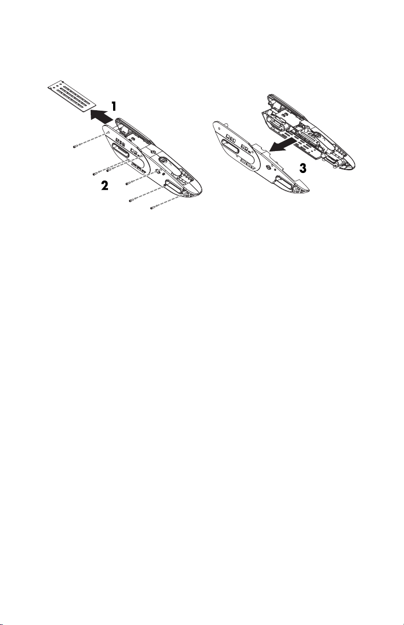
SEPARATE FRAME
To remove the Camera, VTX or Control Module, the frame must be separated. All
4 arms must be removed first.
12
Page 13

SPARE PARTS
1 RISE2020 FPV VTX Antenna
2 RISE2009 Prop Nuts CW/CCW
3 RISE2010 Props CW/CCW 2 Yellow/2 Black
4 RISE2019 Camera VTX CASE
5 RISE2001 Top Cover
6 RISE2017 25mW VTX Camera
6 RISE2018 200mW VTX Camera
7 RISE2007 FC Board Module with Arm sockets
8 RISE2025 Control Board Dampers (4)
9 RISE2015 Frame Left and Right
10 RISE2006 L/R Arm CCW Motor ESC
11 RISE2004 L/F Arm CW Motor ESC
12 RISE2003 R/F Arm CCW Motor ESC
13 RISE2005 R/R Arm CW Motor ESC
14 RISE2000 Canopy
15 RISE2026 Motor Shields (4)
16 RISE2022 LiPo 3S 11.1V 1500mAH
17 RISE2002 Battery Cover
18 RISE2013 L/R Arm Top and Bottom
19 RISE2011 L/F Arm Top and Bottom
20 RISE2012 R/F Arm Top and Bottom
21 RISE2014 R/R Arm Top and Bottom
22 RISE2016 LED Arm Covers (4)
23 RISE2008 Landing Gear (4) with mounting screws (12)
RISE2021 Screw Set
RISJ2000 Transmitter 6-Channel
GOGGLES PARTS
TACZ5610 FPV-G1 Head Strap
TACZ5612 FPV-G1 Face Plate Foam
MONITOR PARTS AND ACCESSORIES
TACZ5600 FPV-RM2 Sun Shield
TACZ5602 FPV-RM2 Tripod Mount
TACZ5300 FPV 5.8GHz RP-SMA TX Antenna Short 110mm 0.95dBi
TACZ5305 FPV 5.8GHZ Cloverleaf Antenna 3dBi
OTHER OPTIONAL PARTS AND ACCESSORIES
RISE2509 RX Flight control board extension cable
TACZ1010 4G Class 10 Micro Memory Card
TACZ5604 USB Micro SD Card Reader
TACL0625 TR625 6-Channel SLT Receiver Twin Antennas
TACJ2650 TTX650 6-Channel SLT Computer Transmitter
DTXP4620 Duratrax Li-24 2S-4S AC Balance Charger
13
Page 14

14
Page 15

™
BATTERY PRECAUTIONS
The RISE Vusion uses a lithium polymer (LiPo) battery. Follow these precautions
to ensure safe and trouble-free operation.
ALWAYS disconnect the battery from the quadcopter when not in use.
•
Do not attempt to use this charger with NiCd or NiMH battery packs.
•
Do not attempt to use a damaged battery.
•
This product contains a LiPo battery that must be recycled or disposed of properly.
•
Do not leave the charger unattended while charging. Disconnect the battery and
•
unplug the charger immediately if either becomes hot! However, it is normal for the
charger to get warm.
Disconnect the battery from the charger and carefully move the battery to a reproof
•
location if the battery begins to swell or smoke!
Never allow the battery temperature to exceed 140° F [60° C].
•
Do not attempt to charge a battery if it is swollen or hot.
•
Do not place the charger or any battery on a ammable surface or near combustible
•
materials while in use.
Never disassemble or modify pack wiring in any way or puncture cells.
•
Never charge inside a vehicle.
•
Always disconnect the battery and unplug the charger when not in use.
•
Land your model immediately when the LEDs ash to indicate that the battery power
•
is low. Recharge the battery before attempting another ight. A dangerous situation
can occur when attempting to recharge an over-discharged battery!
ALWAYS keep a supply of sand accessible when charging. Dumping sand on the
•
battery will extinguish a LiPo chemical re.
ALWAYS KEEP OUT OF REACH OF CHILDREN
•
FCC PRECAUTIONS
FCC RADIATION EXPOSURE STATEMENT
This equipment complies with FCC RF radiation exposure limits set forth for an uncontrolled
environment. This transmitter must not be co-located or operating in conjunction with any
other antenna or transmitter.
Any Changes or mod i f i cat i on s not exp r essl y appr ov ed by t he par t y
r espons i bl e f or c ompl i anc e c ou l d v oi d t he us er ' s au t hor i t y
t o oper at e t he equi pmen t .
This device complies with part 15 of the FCC rules. Changes or modi cations not expressly
approved by Tactic will void the user’s authority to operate this Tx. Operation is subject to the
following two conditions:
(1) This device may not cause harmful interference.
(2) This device must accept any interference received, including interference that may cause
undesired operation.
Note: This equipment has been tested and found to comply with the limits for a Class B digital
device, pursuant to part 15 of the FCC Rules. These limits are designed to provide reasonable
protection against harmful interference in a residential installation. This equipment generates
uses and can radiate radio frequency energy and, if not installed and used in accordance with
the instructions, may cause harmful interference to radio communications. However, there is
no guarantee that interference will not occur in a particular installation. If this equipment does
cause harmful interference to radio or television reception, which can be determined by turning
the equipment off and on, the user is encouraged to try to correct the interference by one or
more of the following measures:
Reorient or relocate the receiving antenna.
•
Increase the separation between the equipment and receiver.
•
Connect the equipment into an outlet on a circuit different from that to which the receiver
•
is connected.
Consult the dealer or an experienced radio/TV technician for help
•
RISE J2000 Transmitter FCC ID: IYFJ2000
RISE 25mW VTx FCC ID: IYF0205
CE COMPLIANCE INFORMATION
FOR THE EUROPEAN UNION
INSTRUCTIONS FOR DISPOSAL OF WASTE EQUIPMENT BY PRIVATE
USERS IN THE EUROPEAN UNION:
This symbol on the product or its packaging indicates this product must not be disposed of with
other household waste. Instead, it is the user’s responsibility to dispose of their waste equipment
by handing it over to a designated collection point for the recycling of waste electrical and
electronic equipment. The separate collection and recycling of your waste equipment at the time
of di spo sal wil l help to co nse rve nat ural res our ces and e nsu re tha t it is re cyc led in a m ann er tha t
protects human health and the environment. For more information about where you can drop
off your waste equipment for recycling, please contact your local city of ce, your household
waste disposal service or location where you purchased the product.
DECLARATION OF CONFORMITY:
Product:
Item number: RISJ2000 J2000
Equipment class: 1
J2000 transmitter: The objects of the declaration described here are in conformity
with the requirements of the speci cations listed below, following the provisions of the
European 2014/35/EU Low Voltage Directive:
The objects of the declaration described here are in conformity with the requirements of
the speci cations listed below, following the provisions of the European R&TTE directive
1999/5/EC:
Technical requirements for radio equipment
Product: RISE 5.8GHz 25mW VTx
Technical requirements for radio equipment
Hobbico, Inc.
2904 Research Road
Champaign, IL USA 61826
Distributed in Europe by Revell GmbH
D-32257 Bünde Germany
RISE 2.4GHz 6-Channel Tx Rx
EN 60950-1:2013 Safety
EN300 328 V1.9.1.
ETSI EN 300 328 V1.9.1 (2015-02); ETSI EN 301 489-1
V1.9.2 (2011-09); ETSI EN 301 489-3 V1.6.1 (2013-08); EN
62479:2010 General EMC requirements for radio equipment
ETSI EN 300 440-2 V1.4.1 (2010-08)
V1.9.2 (2011-09); ETSI EN 301 489-3 V1.6.1 (2013-08); EN
62479:2010 General EMC requirements for radio equipment
; ETSI EN 301 489-1
© 2016 RISE, a Hobbico company. RISE0 200/05 Addn1MADE IN CHINA
 Loading...