

Page 1
OM-923 223 112D
2008−10
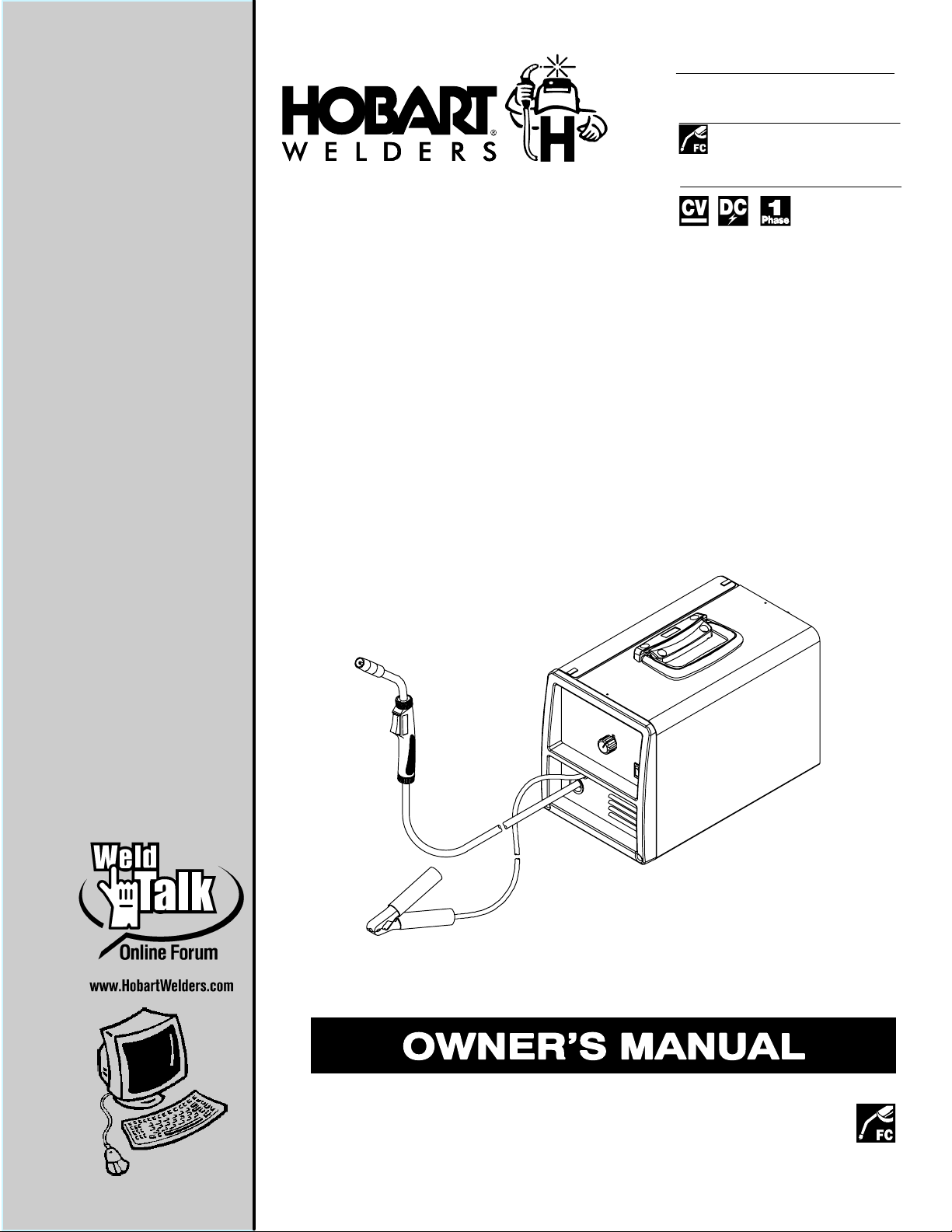
Processes
Flux Cored (FCAW) Welding
Description
Arc Welding Power Source And
Wire Feeder
R
Handler 125 EZ
And H-9B Gun
File: Flux Cored (FCAW)
Page 2
From Hobart to You
Thank you and congratulations on choosing Hobart. Now you can get the
job done and get it done right. We know you don’t have time to do it any
other way.
This Owner’s Manual is designed to help you get the most out of your
Hobart products. Please take time to read the Safety precautions. They
will help you protect yourself against potential hazards on the worksite.
We’ve made installation and operation quick
and easy. With Hobart you can count on years
of reliable service with proper maintenance.
And if for some reason the unit needs repair,
there’s a Troubleshooting section that will help
you figure out what the problem is. The parts
list will then help you to decide the exact part
Hobart is registered to the
ISO 9001:2000 Quality
System Standard.
you may need to fix the problem. Warranty and
service information for your particular model
are also provided.
Working as hard as you
do − every power source
from Hobart is backed by
the best warranty in the
business.
Hobart Welders manufactures a full line
of welders and welding related equipment.
For information on other quality Hobart products, contact your local Hobart
distributor to receive the latest full line catalog or individual specification sheets.
To locate your nearest distributor or service agency call 1-877-Hobart1 or
visit our website at www.HobartWelders.com.
For Technical Help call 1-800-332-3281.
Hob_Thank 4/05
Protect Your Investment!
Register your product at:
HobartWelders.com
Page 3

TABLE OF CONTENTS
SECTION 1 − SAFETY PRECAUTIONS - READ BEFORE USING 1. . . . . . . . . . . . . . . . . . . . . . . . . . . . . . . . .
1-1. Symbol Usage 1. . . . . . . . . . . . . . . . . . . . . . . . . . . . . . . . . . . . . . . . . . . . . . . . . . . . . . . . . . . . . . . . . . . . . . .
1-2. Arc Welding Hazards 1. . . . . . . . . . . . . . . . . . . . . . . . . . . . . . . . . . . . . . . . . . . . . . . . . . . . . . . . . . . . . . . . .
1-3. Additional Symbols For Installation, Operation, And Maintenance 3. . . . . . . . . . . . . . . . . . . . . . . . . . . .
1-4. California Proposition 65 Warnings 4. . . . . . . . . . . . . . . . . . . . . . . . . . . . . . . . . . . . . . . . . . . . . . . . . . . . . .
1-5. Principal Safety Standards 4. . . . . . . . . . . . . . . . . . . . . . . . . . . . . . . . . . . . . . . . . . . . . . . . . . . . . . . . . . . .
1-6. EMF Information 4. . . . . . . . . . . . . . . . . . . . . . . . . . . . . . . . . . . . . . . . . . . . . . . . . . . . . . . . . . . . . . . . . . . . .
SECTION 2 − CONSIGNES DE SÉCURITÉ − LIRE AVANT UTILISATION 5. . . . . . . . . . . . . . . . . . . . . . . . . .
2-1. Symboles utilisés 5. . . . . . . . . . . . . . . . . . . . . . . . . . . . . . . . . . . . . . . . . . . . . . . . . . . . . . . . . . . . . . . . . . . .
2-2. Dangers relatifs au soudage à l’arc 5. . . . . . . . . . . . . . . . . . . . . . . . . . . . . . . . . . . . . . . . . . . . . . . . . . . . .
2-3. Dangers supplémentaires en relation avec l’installation, le fonctionnement et la maintenance 7. . . . .
2-4. Proposition californienne 65 Avertissements 8. . . . . . . . . . . . . . . . . . . . . . . . . . . . . . . . . . . . . . . . . . . . . .
2-5. Principales normes de sécurité 9. . . . . . . . . . . . . . . . . . . . . . . . . . . . . . . . . . . . . . . . . . . . . . . . . . . . . . . . .
2-6. Information EMF 9. . . . . . . . . . . . . . . . . . . . . . . . . . . . . . . . . . . . . . . . . . . . . . . . . . . . . . . . . . . . . . . . . . . . .
SECTION 3 − SPECIFICATIONS 11. . . . . . . . . . . . . . . . . . . . . . . . . . . . . . . . . . . . . . . . . . . . . . . . . . . . . . . . . . . . . .
3-1. Specifications 11. . . . . . . . . . . . . . . . . . . . . . . . . . . . . . . . . . . . . . . . . . . . . . . . . . . . . . . . . . . . . . . . . . . . . . .
3-2. Duty Cycle And Overheating 11. . . . . . . . . . . . . . . . . . . . . . . . . . . . . . . . . . . . . . . . . . . . . . . . . . . . . . . . . . .
3-3. Volt-Ampere Curves 12. . . . . . . . . . . . . . . . . . . . . . . . . . . . . . . . . . . . . . . . . . . . . . . . . . . . . . . . . . . . . . . . . .
SECTION 4 − INSTALLATION 13. . . . . . . . . . . . . . . . . . . . . . . . . . . . . . . . . . . . . . . . . . . . . . . . . . . . . . . . . . . . . . . .
4-1. Installing Work Clamp 13. . . . . . . . . . . . . . . . . . . . . . . . . . . . . . . . . . . . . . . . . . . . . . . . . . . . . . . . . . . . . . . . .
4-2. Process/Polarity Table 13. . . . . . . . . . . . . . . . . . . . . . . . . . . . . . . . . . . . . . . . . . . . . . . . . . . . . . . . . . . . . . . .
4-3. Polarity 13. . . . . . . . . . . . . . . . . . . . . . . . . . . . . . . . . . . . . . . . . . . . . . . . . . . . . . . . . . . . . . . . . . . . . . . . . . . . .
4-4. Installing Wire Spool And Adjusting Hub Tension 14. . . . . . . . . . . . . . . . . . . . . . . . . . . . . . . . . . . . . . . . . .
4-5. Selecting A Location And Connecting Input Power For 115 VAC Model 15. . . . . . . . . . . . . . . . . . . . . . . .
4-6. Installing Contact Tip And Nozzle 16. . . . . . . . . . . . . . . . . . . . . . . . . . . . . . . . . . . . . . . . . . . . . . . . . . . . . . .
4-7. Threading Welding Wire 17. . . . . . . . . . . . . . . . . . . . . . . . . . . . . . . . . . . . . . . . . . . . . . . . . . . . . . . . . . . . . . .
SECTION 5 − OPERATION 18. . . . . . . . . . . . . . . . . . . . . . . . . . . . . . . . . . . . . . . . . . . . . . . . . . . . . . . . . . . . . . . . . .
5-1. Controls 18. . . . . . . . . . . . . . . . . . . . . . . . . . . . . . . . . . . . . . . . . . . . . . . . . . . . . . . . . . . . . . . . . . . . . . . . . . . .
5-2. Operating The Gun 19. . . . . . . . . . . . . . . . . . . . . . . . . . . . . . . . . . . . . . . . . . . . . . . . . . . . . . . . . . . . . . . . . . .
SECTION 6 − MAINTENANCE &TROUBLESHOOTING 20. . . . . . . . . . . . . . . . . . . . . . . . . . . . . . . . . . . . . . . . . .
6-1. Routine Maintenance 20. . . . . . . . . . . . . . . . . . . . . . . . . . . . . . . . . . . . . . . . . . . . . . . . . . . . . . . . . . . . . . . . .
6-2. Overload Protection 20. . . . . . . . . . . . . . . . . . . . . . . . . . . . . . . . . . . . . . . . . . . . . . . . . . . . . . . . . . . . . . . . . .
6-3. Drive Motor Protection 20. . . . . . . . . . . . . . . . . . . . . . . . . . . . . . . . . . . . . . . . . . . . . . . . . . . . . . . . . . . . . . . .
6-4. Changing Drive Roll Or Wire Inlet Guide 21. . . . . . . . . . . . . . . . . . . . . . . . . . . . . . . . . . . . . . . . . . . . . . . . .
6-5. Replacing Gun Contact Tip 22. . . . . . . . . . . . . . . . . . . . . . . . . . . . . . . . . . . . . . . . . . . . . . . . . . . . . . . . . . . .
6-6. Cleaning Gun Liner 23. . . . . . . . . . . . . . . . . . . . . . . . . . . . . . . . . . . . . . . . . . . . . . . . . . . . . . . . . . . . . . . . . . .
6-7. Replacing Gun Liner 24. . . . . . . . . . . . . . . . . . . . . . . . . . . . . . . . . . . . . . . . . . . . . . . . . . . . . . . . . . . . . . . . . .
6-8. Troubleshooting Table 26. . . . . . . . . . . . . . . . . . . . . . . . . . . . . . . . . . . . . . . . . . . . . . . . . . . . . . . . . . . . . . . .
SECTION 7 − ELECTRICAL DIAGRAM 27. . . . . . . . . . . . . . . . . . . . . . . . . . . . . . . . . . . . . . . . . . . . . . . . . . . . . . . .
Page 4

TABLE OF CONTENTS
SECTION 8 − WIRE WELDING GUIDELINES 28. . . . . . . . . . . . . . . . . . . . . . . . . . . . . . . . . . . . . . . . . . . . . . . . . . .
8-1. Typical FCAW Process Connections 28. . . . . . . . . . . . . . . . . . . . . . . . . . . . . . . . . . . . . . . . . . . . . . . . . . . .
8-2. Typical Control Settings 29. . . . . . . . . . . . . . . . . . . . . . . . . . . . . . . . . . . . . . . . . . . . . . . . . . . . . . . . . . . . . . .
8-3. Holding And Positioning Welding Gun 30. . . . . . . . . . . . . . . . . . . . . . . . . . . . . . . . . . . . . . . . . . . . . . . . . . .
8-4. Conditions That Affect Weld Bead Shape 31. . . . . . . . . . . . . . . . . . . . . . . . . . . . . . . . . . . . . . . . . . . . . . . .
8-5. Gun Movement During Welding 32. . . . . . . . . . . . . . . . . . . . . . . . . . . . . . . . . . . . . . . . . . . . . . . . . . . . . . . .
8-6. Poor Weld Bead Characteristics 32. . . . . . . . . . . . . . . . . . . . . . . . . . . . . . . . . . . . . . . . . . . . . . . . . . . . . . . .
8-7. Good Weld Bead Characteristics 32. . . . . . . . . . . . . . . . . . . . . . . . . . . . . . . . . . . . . . . . . . . . . . . . . . . . . . .
8-8. Troubleshooting − Excessive Spatter 33. . . . . . . . . . . . . . . . . . . . . . . . . . . . . . . . . . . . . . . . . . . . . . . . . . . .
8-9. Troubleshooting − Porosity 33. . . . . . . . . . . . . . . . . . . . . . . . . . . . . . . . . . . . . . . . . . . . . . . . . . . . . . . . . . . .
8-10. Troubleshooting − Excessive Penetration 33. . . . . . . . . . . . . . . . . . . . . . . . . . . . . . . . . . . . . . . . . . . . . . . .
8-11. Troubleshooting − Lack Of Penetration 34. . . . . . . . . . . . . . . . . . . . . . . . . . . . . . . . . . . . . . . . . . . . . . . . . .
8-12. Troubleshooting − Incomplete Fusion 34. . . . . . . . . . . . . . . . . . . . . . . . . . . . . . . . . . . . . . . . . . . . . . . . . . . .
8-13. Troubleshooting − Burn-Through 34. . . . . . . . . . . . . . . . . . . . . . . . . . . . . . . . . . . . . . . . . . . . . . . . . . . . . . . .
8-14. Troubleshooting − Waviness Of Bead 35. . . . . . . . . . . . . . . . . . . . . . . . . . . . . . . . . . . . . . . . . . . . . . . . . . .
8-15. Troubleshooting − Distortion 35. . . . . . . . . . . . . . . . . . . . . . . . . . . . . . . . . . . . . . . . . . . . . . . . . . . . . . . . . . .
8-16. Troubleshooting Guide For Semiautomatic Welding Equipment 35. . . . . . . . . . . . . . . . . . . . . . . . . . . . . .
SECTION 9 − PARTS LIST 36. . . . . . . . . . . . . . . . . . . . . . . . . . . . . . . . . . . . . . . . . . . . . . . . . . . . . . . . . . . . . . . . . . .
WARRANTY
Page 5
SECTION 1 − SAFETY PRECAUTIONS - READ BEFORE USING
7
Protect yourself and others from injury — read and follow these precautions.
1-1. Symbol Usage
som _2007−04
DANGER! − Indicates a hazardous situation which, if
not avoided, will result in death or serious injury. The
possible hazards are shown in the adjoining symbols
or explained in the text.
Indicates a hazardous situation which, if not avoided,
could result in death or serious injury. The possible
hazards are shown in the adjoining symbols or explained in the text.
NOTICE − Indicates statements not related to personal injury.
1-2. Arc Welding Hazards
The symbols shown below are used throughout this manual
to call attention to and identify possible hazards. When you
see the symbol, watch out, and follow the related instructions
to avoid the hazard. The safety information given below is
only a summary of the more complete safety information
found in the Safety Standards listed in Section 1-5. Read and
follow all Safety Standards.
Only qualified persons should install, operate, maintain, and
repair this unit.
During operation, keep everybody, especially children, away.
ELECTRIC SHOCK can kill.
Touching live electrical parts can cause fatal shocks
or severe burns. The electrode and work circuit is
electrically live whenever the output is on. The input
live when power is on. In semiautomatic or automatic wire welding, the
wire, wire reel, drive roll housing, and all metal parts touching the
welding wire are electrically live. Incorrectly installed or improperly
grounded equipment is a hazard.
D Do not touch live electrical parts.
D Wear dry, hole-free insulating gloves and body protection.
D Insulate yourself from work and ground using dry insulating mats
or covers big enough to prevent any physical contact with the work
or ground.
D Do not use AC output in damp areas, if movement is confined, or if
there is a danger of falling.
D Use AC output ONLY if required for the welding process.
D If AC output is required, use remote output control if present on
unit.
D Additional safety precautions are required when any of the follow-
ing electrically hazardous conditions are present: in damp
locations or while wearing wet clothing; on metal structures such
as floors, gratings, or scaffolds; when in cramped positions such
as sitting, kneeling, or lying; or when there is a high risk of unavoidable or accidental contact with the workpiece or ground. For these
conditions, use the following equipment in order presented: 1) a
semiautomatic DC constant voltage (wire) welder, 2) a DC manual
(stick) welder, or 3) an AC welder with reduced open-circuit voltage. In most situations, use of a DC, constant voltage wire welder
is recommended. And, do not work alone!
D Disconnect input power or stop engine before installing or
servicing this equipment. Lockout/tagout input power according to
OSHA 29 CFR 1910.147 (see Safety Standards).
D Properly install and ground this equipment according to its
Owner’s Manual and national, state, and local codes.
power circuit and machine internal circuits are also
. Indicates special instructions.
This group of symbols means Warning! Watch Out! ELECTRIC
SHOCK, MOVING PARTS, and HOT PARTS hazards. Consult symbols and related instructions below for necessary actions to avoid the
hazards.
D Always verify the supply ground − check and be sure that input
power cord ground wire is properly connected to ground terminal in
disconnect box or that cord plug is connected to a properly
grounded receptacle outlet.
D When making input connections, attach proper grounding conduc-
tor first − double-check connections.
D Keep cords dry, free of oil and grease, and protected from hot metal
and sparks.
D Frequently inspect input power cord for damage or bare wiring −
replace cord immediately if damaged − bare wiring can kill.
D Turn off all equipment when not in use.
D Do not use worn, damaged, undersized, or poorly spliced cables.
D Do not drape cables over your body.
D If earth grounding of the workpiece is required, ground it directly
with a separate cable.
D Do not touch electrode if you are in contact with the work, ground,
or another electrode from a different machine.
D Do not touch electrode holders connected to two welding ma-
chines at the same time since double open-circuit voltage will be
present.
D Use only well-maintained equipment. Repair or replace damaged
parts at once. Maintain unit according to manual.
D Wear a safety harness if working above floor level.
D Keep all panels and covers securely in place.
D Clamp work cable with good metal-to-metal contact to workpiece
or worktable as near the weld as practical.
D Insulate work clamp when not connected to workpiece to prevent
contact with any metal object.
D Do not connect more than one electrode or work cable to any
single weld output terminal.
SIGNIFICANT DC VOLTAGE exists in inverter-type
welding power sources after removal of input
power.
D Turn Off inverter, disconnect input power, and discharge input
capacitors according to instructions in Maintenance Section
before touching any parts.
HOT PARTS can cause severe burns.
D Do not touch hot parts bare handed.
D Allow cooling period before working on gun or
torch.
D To handle hot parts, use proper tools and/or
wear heavy, insulated welding gloves and
clothing to prevent burns.
OM-923 Page 1
Page 6
FUMES AND GASES can be hazardous.
Welding produces fumes and gases. Breathing
these fumes and gases can be hazardous to your
health.
D Keep your head out of the fumes. Do not breathe the fumes.
D If inside, ventilate the area and/or use local forced ventilation at the
arc to remove welding fumes and gases.
D If ventilation is poor, wear an approved air-supplied respirator.
D Read and understand the Material Safety Data Sheets (MSDSs)
and the manufacturer’s instructions for metals, consumables,
coatings, cleaners, and degreasers.
D Work in a confined space only if it is well ventilated, or while
wearing an air-supplied respirator. Always have a trained watchperson nearby. Welding fumes and gases can displace air and
lower the oxygen level causing injury or death. Be sure the breathing air is safe.
D Do not weld in locations near degreasing, cleaning, or spraying op-
erations. The heat and rays of the arc can react with vapors to form
highly toxic and irritating gases.
D Do not weld on coated metals, such as galvanized, lead, or
cadmium plated steel, unless the coating is removed from the weld
area, the area is well ventilated, and while wearing an air-supplied
respirator. The coatings and any metals containing these elements
can give off toxic fumes if welded.
ARC RAYS can burn eyes and skin.
Arc rays from the welding process produce intense
visible and invisible (ultraviolet and infrared) rays
that can burn eyes and skin. Sparks fly off from the
weld.
D Wear an approved welding helmet fitted with a proper shade of fil-
ter lenses to protect your face and eyes when welding or watching
(see ANSI Z49.1 and Z87.1 listed in Safety Standards).
D Wear approved safety glasses with side shields under your
helmet.
D Use protective screens or barriers to protect others from flash,
glare and sparks; warn others not to watch the arc.
D Wear protective clothing made from durable, flame-resistant mate-
rial (leather, heavy cotton, or wool) and foot protection.
WELDING can cause fire or explosion.
D Do not use welder to thaw frozen pipes.
D Remove stick electrode from holder or cut off welding wire at
contact tip when not in use.
D Wear oil-free protective garments such as leather gloves, heavy
shirt, cuffless trousers, high shoes, and a cap.
D Remove any combustibles, such as a butane lighter or matches,
from your person before doing any welding.
D After completion of work, inspect area to ensure it is free of sparks,
glowing embers, and flames.
D Use only correct fuses or circuit breakers. Do not oversize or by-
pass them.
D Follow requirements in OSHA 1910.252 (a) (2) (iv) and NFPA 51B
for hot work and have a fire watcher and extinguisher nearby.
FLYING METAL or DIRT can injure eyes.
D Welding, chipping, wire brushing, and grinding
cause sparks and flying metal. As welds cool,
they can throw off slag.
D Wear approved safety glasses with side
shields even under your welding helmet.
BUILDUP OF GAS can injure or kill.
D Shut off shielding gas supply when not in use.
D Always ventilate confined spaces or use
approved air-supplied respirator.
MAGNETIC FIELDS can affect Implanted
Medical Devices.
D Wearers of Pacemakers and other Implanted
Medical Devices should keep away.
D Implanted Medical Device wearers should consult their doctor
and the device manufacturer before going near arc welding, spot
welding, gouging, plasma arc cutting, or induction heating
operations.
NOISE can damage hearing.
Noise from some processes or equipment can
damage hearing.
D Wear approved ear protection if noise level is
high.
Welding on closed containers, such as tanks,
drums, or pipes, can cause them to blow up. Sparks
can fly off from the welding arc. The flying sparks, hot
burns. Accidental contact of electrode to metal objects can cause
sparks, explosion, overheating, or fire. Check and be sure the area is
safe before doing any welding.
D Remove all flammables within 35 ft (10.7 m) of the welding arc. If
this is not possible, tightly cover them with approved covers.
D Do not weld where flying sparks can strike flammable material.
D Protect yourself and others from flying sparks and hot metal.
D Be alert that welding sparks and hot materials from welding can
easily go through small cracks and openings to adjacent areas.
D Watch for fire, and keep a fire extinguisher nearby.
D Be aware that welding on a ceiling, floor, bulkhead, or partition can
cause fire on the hidden side.
D Do not weld on closed containers such as tanks, drums, or pipes,
unless they are properly prepared according to AWS F4.1 (see
Safety Standards).
D Do not weld where the atmosphere may contain flammable dust,
gas, or liquid vapors (such as gasoline).
D Connect work cable to the work as close to the welding area as
practical to prevent welding current from traveling long, possibly
unknown paths and causing electric shock, sparks, and fire
hazards.
OM-923 Page 2
workpiece, and hot equipment can cause fires and
CYLINDERS can explode if damaged.
Shielding gas cylinders contain gas under high
pressure. If damaged, a cylinder can explode. Since
gas cylinders are normally part of the welding
process, be sure to treat them carefully.
D Protect compressed gas cylinders from excessive heat, mechani-
cal shocks, physical damage, slag, open flames, sparks, and arcs.
D Install cylinders in an upright position by securing to a stationary
support or cylinder rack to prevent falling or tipping.
D Keep cylinders away from any welding or other electrical circuits.
D Never drape a welding torch over a gas cylinder.
D Never allow a welding electrode to touch any cylinder.
D Never weld on a pressurized cylinder − explosion will result.
D Use only correct shielding gas cylinders, regulators, hoses, and fit-
tings designed for the specific application; maintain them and
associated parts in good condition.
D Turn face away from valve outlet when opening cylinder valve.
D Keep protective cap in place over valve except when cylinder is in
use or connected for use.
D Use the right equipment, correct procedures, and sufficient num-
ber of persons to lift and move cylinders.
D Read and follow instructions on compressed gas cylinders,
associated equipment, and Compressed Gas Association (CGA)
publication P-1 listed in Safety Standards.
Page 7
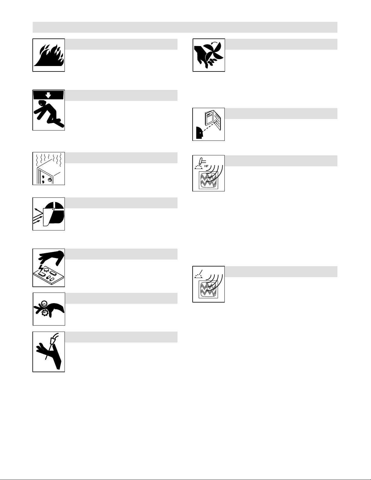
1-3. Additional Symbols For Installation, Operation, And Maintenance
FIRE OR EXPLOSION hazard.
D Do not install or place unit on, over, or near
combustible surfaces.
D Do not install unit near flammables.
D Do not overload building wiring − be sure power supply system is
properly sized, rated, and protected to handle this unit.
FALLING UNIT can cause injury.
D Use lifting eye to lift unit only, NOT running
gear, gas cylinders, or any other accessories.
D Use equipment of adequate capacity to lift and
support unit.
D If using lift forks to move unit, be sure forks are
long enough to extend beyond opposite side of
unit.
OVERUSE can cause OVERHEATING
D Allow cooling period; follow rated duty cycle.
D Reduce current or reduce duty cycle before
starting to weld again.
D Do not block or filter airflow to unit.
FLYING SPARKS can cause injury.
D Wear a face shield to protect eyes and face.
D Shape tungsten electrode only on grinder with
proper guards in a safe location wearing proper
face, hand, and body protection.
D Sparks can cause fires — keep flammables away.
STATIC (ESD) can damage PC boards.
MOVING PARTS can cause injury.
D Keep away from moving parts such as fans.
D Keep all doors, panels, covers, and guards
closed and securely in place.
D Have only qualified persons remove doors, panels, covers, or
guards for maintenance as necessary.
D Reinstall doors, panels, covers, or guards when maintenance is
finished and before reconnecting input power.
READ INSTRUCTIONS.
D Read Owner’s Manual before using or servic-
ing unit.
D Use only genuine replacement parts from the
manufacturer.
H.F. RADIATION can cause interference.
D High-frequency (H.F.) can interfere with radio
navigation, safety services, computers, and
communications equipment.
D Have only qualified persons familiar with
electronic equipment perform this installation.
D The user is responsible for having a qualified electrician prompt-
ly correct any interference problem resulting from the installation.
D If notified by the FCC about interference, stop using the
equipment at once.
D Have the installation regularly checked and maintained.
D Keep high-frequency source doors and panels tightly shut, keep
spark gaps at correct setting, and use grounding and shielding to
minimize the possibility of interference.
D Put on grounded wrist strap BEFORE handling
boards or parts.
D Use proper static-proof bags and boxes to
store, move, or ship PC boards.
MOVING PARTS can cause injury.
D Keep away from moving parts.
D Keep away from pinch points such as drive
rolls.
WELDING WIRE can cause injury.
D Do not press gun trigger until instructed to do
so.
D Do not point gun toward any part of the body,
other people, or any metal when threading
welding wire.
ARC WELDING can cause interference.
D Electromagnetic energy can interfere with
sensitive electronic equipment such as
computers and computer-driven equipment
such as robots.
D Be sure all equipment in the welding area is
electromagnetically compatible.
D To reduce possible interference, keep weld cables as short as
possible, close together, and down low, such as on the floor.
D Locate welding operation 100 meters from any sensitive elec-
tronic equipment.
D Be sure this welding machine is installed and grounded
according to this manual.
D If interference still occurs, the user must take extra measures
such as moving the welding machine, using shielded cables,
using line filters, or shielding the work area.
OM-923 Page 3
Page 8

1-4. California Proposition 65 Warnings
Welding or cutting equipment produces fumes or gases
which contain chemicals known to the State of California to
cause birth defects and, in some cases, cancer. (California
Health & Safety Code Section 25249.5 et seq.)
Battery posts, terminals and related accessories contain lead
and lead compounds, chemicals known to the State of
California to cause cancer and birth defects or other
reproductive harm. Wash hands after handling.
1-5. Principal Safety Standards
Safety in Welding, Cutting, and Allied Processes, ANSI Standard Z49.1,
from Global Engineering Documents (phone: 1-877-413-5184, website:
www.global.ihs.com).
Recommended Safe Practices for the Preparation for Welding and Cutting of Containers and Piping, American Welding Society Standard
AWS F4.1, from Global Engineering Documents (phone:
1-877-413-5184, website: www.global.ihs.com).
National Electrical Code, NFPA Standard 70, from National Fire Protection Association, P.O. Box 9101, Quincy, MA 02269-9101 (phone:
617-770-3000, website: www.nfpa.org and www. sparky.org).
Safe Handling of Compressed Gases in Cylinders, CGA Pamphlet P-1,
from Compressed Gas Association, 4221 Walney Road, 5th Floor,
Chantilly, VA 20151 (phone: 703-788-2700, website:www.cganet.com).
Code for Safety in Welding and Cutting, CSA Standard W117.2, from
Canadian Standards Association, Standards Sales, 5060 Mississauga,
For Gasoline Engines:
Engine exhaust contains chemicals known to the State of
California to cause cancer, birth defects, or other reproductive harm.
For Diesel Engines:
Diesel engine exhaust and some of its constituents are
known to the State of California to cause cancer, birth
defects, and other reproductive harm.
Ontario, Canada L4W 5NS (phone: 800-463-6727 or in Toronto
416-747-4044, website: www.csa-international.org).
Safe Practice For Occupational And Educational Eye And Face Protection, ANSI Standard Z87.1, from American National Standards Institute,
25 West 43rd Street, New York, NY 10036–8002 (phone:
212-642-4900, website: www.ansi.org).
Standard for Fire Prevention During Welding, Cutting, and Other Hot
Work, NFPA Standard 51B, from National Fire Protection Association,
P.O. Box 9101, Quincy, MA 02269-9101 (phone: 617-770-3000, website: www.nfpa.org.
OSHA, Occupational Safety and Health Standards for General Industry, Title 29, Code of Federal Regulations (CFR), Part 1910, Subpart Q,
and Part 1926, Subpart J, from U.S. Government Printing Office, Superintendent of Documents, P.O. Box 371954, Pittsburgh, PA 15250-7954
(phone: 1-866-512-1800) (there are 10 Regional Offices—phone for
Region 5, Chicago, is 312-353-2220, website: www.osha.gov).
1-6. EMF Information
Considerations About Welding And The Effects Of Low Frequency
Electric And Magnetic Fields
Welding current, as it flows through welding cables, will cause electromagnetic fields. There has been and still is some concern about such
fields. However, after examining more than 500 studies spanning 17
years of research, a special blue ribbon committee of the National
Research Council concluded that: “The body of evidence, in the
committee’s judgment, has not demonstrated that exposure to powerfrequency electric and magnetic fields is a human-health hazard.”
However, studies are still going forth and evidence continues to be
examined. Until the final conclusions of the research are reached, you
may wish to minimize your exposure to electromagnetic fields when
welding or cutting.
To reduce magnetic fields in the workplace, use the following
procedures:
1. Keep cables close together by twisting or taping them, or using a
cable cover.
2. Arrange cables to one side and away from the operator.
3. Do not coil or drape cables around your body.
4. Keep welding power source and cables as far away from operator as practical.
5. Connect work clamp to workpiece as close to the weld as possible.
About Implanted Medical Devices:
Implanted Medical Device wearers should consult their doctor and the
device manufacturer before performing or going near arc welding, spot
welding, gouging, plasma arc cutting, or induction heating operations.
If cleared by your doctor, then following the above procedures is recommended.
OM-923 Page 4
Page 9
SECTION 2 − CONSIGNES DE SÉCURITÉ − LIRE AVANT UTILISATION
7
Se protéger et protéger les autres contre le risque de blessure — lire et respecter ces consignes.
2-1. Symboles utilisés
DANGER! − Indique une situation dangereuse qui si on
l’évite pas peut donner la mort ou des blessures graves.
Les dangers possibles sont montrés par les symboles
joints ou sont expliqués dans le texte.
Indique une situation dangereuse qui si on l’évite pas
peut donner la mort ou des blessures graves. Les dangers possibles sont montrés par les symboles joints ou
sont expliqués dans le texte.
NOTE − Indique des déclarations pas en relation avec des blessures
personnelles.
. Indique des instructions spécifiques.
Ce groupe de symboles veut dire Avertissement! Attention! DANGER
DE CHOC ELECTRIQUE, PIECES EN MOUVEMENT, et PIECES
CHAUDES. Consulter les symboles et les instructions ci-dessous y
afférant pour les actions nécessaires afin d’éviter le danger.
2-2. Dangers relatifs au soudage à l’arc
Les symboles représentés ci-dessous sont utilisés dans ce manuel pour attirer l’attention et identifier les dangers possibles. En
présence de l’un de ces symboles, prendre garde et suivre les
instructions afférentes pour éviter tout risque. Les instructions
en matière de sécurité indiquées ci-dessous ne constituent
qu’un sommaire des instructions de sécurité plus complètes
fournies dans les normes de sécurité énumérées dans la Section 2-5. Lire et observer toutes les normes de sécurité.
Seul un personnel qualifié est autorisé à installer, faire fonctionner, entretenir et réparer cet appareil.
Pendant le fonctionnement, maintenir à distance toutes les
personnes, notamment les enfants de l’appareil.
UNE DÉCHARGE ÉLECTRIQUE peut
entraîner la mort.
Le contact d’organes électriques sous tension peut
provoquer des accidents mortels ou des brûlures
graves. Le circuit de l’électrode et de la pièce est
sortie. Le circuit d’alimentation et les circuits internes de la machine
sont également sous tension lorsque l’alimentation est sur Marche.
Dans le mode de soudage avec du fil, le fil, le dérouleur, le bloc de
commande du rouleau et toutes les parties métalliques en contact
avec le fil sont sous tension électrique. Un équipement installé ou mis
à la terre de manière incorrecte ou impropre constitue un danger.
D Ne pas toucher aux pièces électriques sous tension.
D Porter des gants isolants et des vêtements de protection secs et
sans trous.
D S’isoler de la pièce à couper et du sol en utilisant des housses ou
des tapis assez grands afin d’éviter tout contact physique avec la
pièce à couper ou le sol.
D Ne pas se servir de source électrique à courant électrique dans les
zones humides, dans les endroits confinés ou là où on risque de
tomber.
D Se servir d’une source électrique à courant électrique UNIQUE-
MENT si le procédé de soudage le demande.
D Si l’utilisation d’une source électrique à courant électrique s’avère
nécessaire, se servir de la fonction de télécommande si l’appareil
en est équipé.
D D’autres consignes de sécurité sont nécessaires dans les condi-
tions suivantes : risques électriques dans un environnement
humide ou si l’on porte des vêtements mouillés ; sur des structures
métalliques telles que sols, grilles ou échafaudages ; en position
coincée comme assise, à genoux ou couchée ; ou s’il y a un risque
élevé de contact inévitable ou accidentel avec la pièce à souder ou
le sol. Dans ces conditions, utiliser les équipements suivants,
dans l’ordre indiqué : 1) un poste à souder DC à tension constante
sous tension lorsque le courant est délivré à la
(à fil), 2) un poste à souder DC manuel (électrode) ou 3) un poste à
souder AC à tension à vide réduite. Dans la plupart des situations,
l’utilisation d’un poste à souder DC à fil à tension constante est recommandée. En outre, ne pas travailler seul !
D Couper l’alimentation ou arrêter le moteur avant de procéder à l’in-
stallation, à la réparation ou à l’entretien de l’appareil. Déverrouiller
l’alimentation selon la norme OSHA 29 CFR 1910.147 (voir normes de sécurité).
D Installer le poste correctement et le mettre à la terre convenable-
ment selon les consignes du manuel de l’opérateur et les normes
nationales, provinciales et locales.
D Toujours vérifier la terre du cordon d’alimentation. Vérifier et
s’assurer que le fil de terre du cordon d’alimentation est bien
raccordé à la borne de terre du sectionneur ou que la fiche du
cordon est raccordée à une prise correctement mise à la terre.
D En effectuant les raccordements d’entrée, fixer d’abord le conduc-
teur de mise à la terre approprié et contre-vérifier les connexions.
D Les câbles doivent être exempts d’humidité, d’huile et de graisse;
protégez−les contre les étincelles et les pièces métalliques
chaudes.
D Vérifier fréquemment le cordon d’alimentation afin de s’assurer
qu’il n’est pas altéré ou à nu, le remplacer immédiatement s’il l’est.
Un fil à nu peut entraîner la mort.
D L’équipement doit être hors tension lorsqu’il n’est pas utilisé.
D Ne pas utiliser des câbles usés, endommagés, de grosseur insuffi-
sante ou mal épissés.
D Ne pas enrouler les câbles autour du corps.
D Si la pièce soudée doit être mise à la terre, le faire directement
avec un câble distinct.
D Ne pas toucher l’électrode quand on est en contact avec la pièce,
la terre ou une électrode provenant d’une autre machine.
D Ne pas toucher des porte électrodes connectés à deux machines
en même temps à cause de la présence d’une tension à vide doublée.
D N’utiliser qu’un matériel en bon état. Réparer ou remplacer sur-le-
champ les pièces endommagées. Entretenir l’appareil conformément à ce manuel.
D Porter un harnais de sécurité si l’on doit travailler au-dessus du sol.
D S’assurer que tous les panneaux et couvercles sont correctement
en place.
D Fixer le câble de retour de façon à obtenir un bon contact métal-
métal avec la pièce à souder ou la table de travail, le plus près possible de la soudure.
D Isoler la pince de masse quand pas mis à la pièce pour éviter le
contact avec tout objet métallique.
D Ne pas raccorder plus d’une électrode ou plus d’un câble de
masse à une même borne de sortie de soudage.
fre_som_2007−04
OM-923 Page 5
Page 10
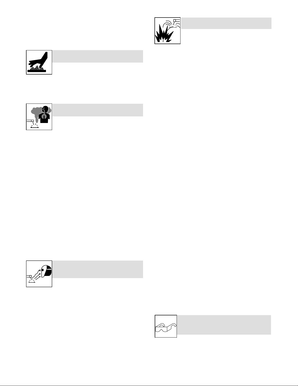
Il reste une TENSION DC NON NÉGLIGEABLE dans
s
e
r
e
e
les sources de soudage onduleur quand on a
coupé l’alimentation.
D Arrêter les convertisseurs, débrancher le courant électrique et
décharger les condensateurs d’alimentation selon les instructions
indiquées dans la partie Entretien avant de toucher les pièces.
DES PIÈCES CHAUDES peuvent
provoquer des brûlures graves.
D Ne pas toucher à mains nues les partie
chaudes.
D Prévoir une période de refroidissement avant d
travailler à l’équipement.
D Ne pas toucher aux pièces chaudes, utiliser les outils recomman
dés et porter des gants de soudage et des vêtements épais pou
éviter les brûlures.
LES FUMÉES ET LES GAZ peuvent
être dangereux.
Le soudage génère des fumées et des gaz. Leur
inhalation peut être dangereux pour votre santé.
D Eloigner votre tête des fumées. Ne pas respirer les fumées.
D À l’intérieur, ventiler la zone et/ou utiliser une ventilation forcée au
niveau de l’arc pour l’évacuation des fumées et des gaz de soudage.
D Si la ventilation est médiocre, porter un respirateur anti-vapeurs
approuvé.
D Lire et comprendre les spécifications de sécurité des matériaux
(MSDS) et les instructions du fabricant concernant les métaux, les
consommables, les revêtements, les nettoyants et les dégraisseurs.
D Travailler dans un espace fermé seulement s’il est bien ventilé ou
en portant un respirateur à alimentation d’air. Demander toujours à
un surveillant dûment formé de se tenir à proximité. Des fumées et
des gaz de soudage peuvent déplacer l’air et abaisser le niveau
d’oxygène provoquant des blessures ou des accidents mortels.
S’assurer que l’air de respiration ne présente aucun danger.
D Ne pas souder dans des endroits situés à proximité d’opérations
de dégraissage, de nettoyage ou de pulvérisation. La chaleur et
les rayons de l’arc peuvent réagir en présence de vapeurs et former des gaz hautement toxiques et irritants.
D Ne pas souder des métaux munis d’un revêtement, tels que l’acier
galvanisé, plaqué en plomb ou au cadmium à moins que le revêtement n’ait été enlevé dans la zone de soudure, que l’endroit soit
bien ventilé, et en portant un respirateur à alimentation d’air. Les
revêtements et tous les métaux renfermant ces éléments peuvent
dégager des fumées toxiques en cas de soudage.
LES RAYONS DE L’ARC peuvent
provoquer des brûlures dans les
yeux et sur la peau.
Le rayonnement de l’arc du procédé de soudag
(ultraviolets et infrarouges) susceptibles de provoquer des brûlure
dans les yeux et sur la peau. Des étincelles sont projetées pendant l
soudage.
D Porter un casque de soudage approuvé muni de verres filtrants
approprié pour protéger visage et yeux pendant le soudage
(voir ANSI Z49.1 et Z87.1 énuméré dans les normes de sécurité).
D Porter des lunettes de sécurité avec écrans latéraux même sous
votre casque.
D Avoir recours à des écrans protecteurs ou à des rideaux pour
protéger les autres contre les rayonnements les éblouissements
et les étincelles ; prévenir toute personne sur les lieux de ne pas
regarder l’arc.
D Porter des vêtements confectionnés avec des matières résistan-
tes et ignifuges (cuir, coton lourd ou laine) et des bottes de
protection.
OM-923 Page 6
génère des rayons visibles et invisibles intense
LE SOUDAGE peut provoquer un in
cendie ou une explosion.
Le soudage effectué sur des conteneurs fermés tels
que des réservoirs, tambours ou des conduites peut
provoquer leur éclatement. Des étincelles peuvent
être projetées de l’arc de soudure. La projection d’étincelles, des
pièces chaudes et des équipements chauds peut provoquer des
incendies et des brûlures. Le contact accidentel de l’électrode avec
des objets métalliques peut provoquer des étincelles, une explosion,
un surchauffement ou un incendie. Avant de commencer le soudage,
vérifier et s’assurer que l’endroit ne présente pas de danger.
D Déplacer toutes les substances inflammables à une distance de
10,7 m de l’arc de soudage. En cas d’impossibilité les recouvrir
soigneusement avec des protections homologués.
D Ne pas souder dans un endroit là où des étincelles peuvent tomber
sur des substances inflammables.
D Se protéger et d’autres personnes de la projection d’étincelles et
de métal chaud.
D Des étincelles et des matériaux chauds du soudage peuvent
facilement passer dans d’autres zones en traversant de petites
fissures et des ouvertures.
D Surveiller tout déclenchement d’incendie et tenir un extincteur à
proximité.
D Le soudage effectué sur un plafond, plancher, paroi ou séparation
peut déclencher un incendie de l’autre côté.
D Ne pas effectuer le soudage sur des conteneurs fermés tels que
des réservoirs, tambours, ou conduites, à moins qu’ils n’aient été
préparés correctement conformément à AWS F4.1 (voir les normes de sécurité).
D Ne soudez pas si l’air ambiant est chargé de particules, gaz, ou va-
peurs inflammables (vapeur d’essence, par exemple).
D Brancher le câble de masse sur la pièce le plus près possible de la
zone de soudage pour éviter le transport du courant sur une
longue distance par des chemins inconnus éventuels en provoquant des risques d’électrocution, d’étincelles et d’incendie.
D Ne pas utiliser le poste de soudage pour dégeler des conduites ge-
lées.
D En cas de non utilisation, enlever la baguette d’électrode du porte-
électrode ou couper le fil à la pointe de contact.
D Porter des vêtements de protection dépourvus d’huile tels que des
gants en cuir, une chemise en matériau lourd, des pantalons sans
revers, des chaussures hautes et un couvre chef.
D Avant de souder, retirer toute substance combustible de vos po-
ches telles qu’un allumeur au butane ou des allumettes.
D Une fois le travail achevé, assurez−vous qu’il ne reste aucune
trace d’étincelles incandescentes ni de flammes.
D Utiliser exclusivement des fusibles ou coupe−circuits appropriés.
Ne pas augmenter leur puissance; ne pas les ponter.
D Une fois le travail achevé, assurez−vous qu’il ne reste aucune
trace d’étincelles incandescentes ni de flammes.
D Utiliser exclusivement des fusibles ou coupe−circuits appropriés.
Ne pas augmenter leur puissance; ne pas les ponter.
D Suivre les recommandations dans OSHA 1910.252(a)(2)(iv) et
NFPA 51B pour les travaux à chaud et avoir de la surveillance et un
extincteur à proximité.
DES PIECES DE METAL ou DES
SALETES peuvent provoquer des
blessures dans les yeux.
D Le soudage, l’écaillement, le passage de la pièce à la brosse en
fil de fer, et le meulage génèrent des étincelles et des particules
métalliques volantes. Pendant la période de refroidissement des
soudures, elles risquent de projeter du laitier.
D Porter des lunettes de sécurité avec écrans latéraux ou un écran
facial.
Page 11
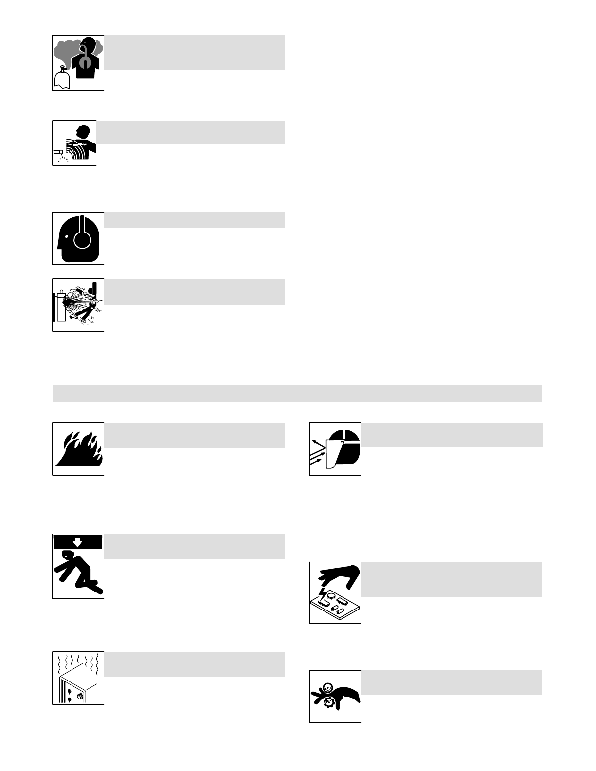
LES ACCUMULATIONS DE GAZ
t
a
n
u
-
risquent de provoquer des blessures
ou même la mort.
D Fermer l’alimentation du gaz protecteur en cas
de non-utilisation.
D Veiller toujours à bien aérer les espaces confi-
nés ou se servir d’un respirateur d’adduction
d’air homologué.
LES CHAMPS MAGNETIQUES peuvent affecter des implants médicaux.
D Porteur de simulateur cardiaque ou autre im-
plants médicaux, rester à distance.
D Les porteurs d’implants doivent d’abord consulter leur médecin
avant de s’approcher des opérations de soudage à l’arc, de soudage par points, de gougeage, du coupage plasma ou de chauffage par induction.
LE BRUIT peut endommager l’ouïe.
Le bruit des processus et des équipements peut
affecter l’ouïe.
D Porter des protections approuvées pour les
oreilles si le niveau sonore est trop élevé.
LES BOUTEILLES peuvent exploser
si elles sont endommagées.
Des bouteilles de gaz protecteur contiennent du gaz
sous haute pression. Si une bouteille est endommagée, elle peut exploser. Du fait que les bouteilles de
dage, les manipuler avec précaution.
gaz font normalement partie du procédé de sou-
D Protéger les bouteilles de gaz comprimé d’une chaleur excessive,
des chocs mécaniques, des dommages physiques, du laitier, des
flammes ouvertes, des étincelles et des arcs.
D Placer les bouteilles debout en les fixant dans un support station-
naire ou dans un porte-bouteilles pour les empêcher de tomber ou
de se renverser.
D Tenir les bouteilles éloignées des circuits de soudage ou autres
circuits électriques.
D Ne jamais placer une torche de soudage sur une bouteille à gaz.
D Une électrode de soudage ne doit jamais entrer en contact avec
une bouteille.
D Ne jamais souder une bouteille pressurisée − risque d’explosion.
D Utiliser seulement des bouteilles de gaz protecteur, régulateurs,
tuyaux et raccords convenables pour cette application spécifique ;
les maintenir ainsi que les éléments associés en bon état.
D Détourner votre visage du détendeur-régulateur lorsque vous
ouvrez la soupape de la bouteille.
D Le couvercle du détendeur doit toujours être en place, sauf lorsque
la bouteille est utilisée ou qu’elle est reliée pour usage ultérieur.
D Utiliser les équipements corrects, les bonnes procédures et suffi-
samment de personnes pour soulever et déplacer les bouteilles.
D Lire et suivre les instructions sur les bouteilles de gaz comprimé,
l’équipement connexe et le dépliant P-1 de la CGA (Compressed
Gas Association) mentionné dans les principales normes de sécurité.
2-3. Dangers supplémentaires en relation avec l’installation, le fonctionnement et la maintenance
Risque D’INCENDIE OU D’EXPLOSION.
D Ne pas placer l’appareil sur, au-dessus ou
à proximité de surfaces inflammables.
D Ne pas installer l’appareil à proximité de pro-
duits inflammables.
D Ne pas surcharger l’installation électrique − s’assurer que
l’alimentation est correctement dimensionnée et protégée avant
de mettre l’appareil en service.
LA CHUTE DE L’APPAREIL peut
blesser.
D Utiliser l’anneau de levage uniquement pour
soulever l’appareil, NON PAS les chariots, les
bouteilles de gaz ou tout autre accessoire.
D Utiliser un équipement de levage de capacité
suffisante pour lever l’appareil.
D En utilisant des fourches de levage pour déplacer l’unité, s’assu-
rer que les fourches sont suffisamment longues pour dépasser
du côté opposé de l’appareil.
L’EMPLOI EXCESSIF peut SURCHAUFFER L’ÉQUIPEMENT.
D Prévoir une période de refroidissement ; re-
specter le cycle opératoire nominal.
D Réduire le courant ou le facteur de marche
avant de poursuivre le soudage.
D Ne pas obstruer les passages d’air du poste.
D Les étincelles risquent de causer un incendie − éloigner toute sub
stance inflammable.
LES ÉTINCELLES VOLANTES risquent de provoquer des blessures.
D Porter un écran facial pour protéger le visage e
les yeux.
D Affûter l’électrode au tungstène uniquement à l
meuleuse dotée de protecteurs. Cette manœuv
re est à exécuter dans un endroit sûr lorsque l’o
porte l’équipement homologué de protection d
visage, des mains et du corps.
LES CHARGES ÉLECTROSTATIQUES peuvent endommager les
circuits imprimés.
D Établir la connexion avec la barrette de terre
avant de manipuler des cartes ou des pièces.
D Utiliser des pochettes et des boîtes antistati-
ques pour stocker, déplacer ou expédier des
cartes de circuits imprimes.
DES ORGANES MOBILES peuvent
provoquer des blessures.
D Ne pas s’approcher des organes mobiles.
D Ne pas s’approcher des points de coincement
tels que des rouleaux de commande.
OM-923 Page 7
Page 12
LES FILS DE SOUDAGE peuvent
provoquer des blessures.
D Ne pas appuyer sur la gâchette avant d’en
avoir reçu l’instruction.
D Ne pas diriger le pistolet vers soi, d’autres per-
sonnes ou toute pièce mécanique en engageant le fil de soudage.
DES ORGANES MOBILES peuvent
provoquer des blessures.
D S’abstenir de toucher des organes mobiles tels
que des ventilateurs.
D Maintenir fermés et verrouillés les portes, pan-
neaux, recouvrements et dispositifs de protection.
D Seules des personnes qualifiées sont autorisées à enlever les
portes, panneaux, recouvrements ou dispositifs de protection
pour l’entretien.
D Remettre les portes, panneaux, recouvrements ou dispositifs de
protection quand l’entretien est terminé et avant de rebrancher
l’alimentation électrique.
LIRE LES INSTRUCTIONS.
D Lisez le manuel d’instructions avant l’utilisation
ou la maintenance de l’appareil.
D N’utiliser que les pièces de rechange recom-
mandées par le constructeur.
D Effectuer régulièrement le contrôle et l’entretien de l’installation.
D Maintenir soigneusement fermés les portes et les panneaux des
sources de haute fréquence, maintenir les éclateurs à une distance correcte et utiliser une terre et un blindage pour réduire les
interférences éventuelles.
LE RAYONNEMENT HAUTE FRÉQUENCE (H.F.) risque de provoquer
des interférences.
D Le rayonnement haute fréquence (H.F.) peut
provoquer des interférences avec les équipements de radio−navigation et de communication, les services de sécurité et les ordinateurs.
D Demander seulement à des personnes qualifiées familiarisées
avec des équipements électroniques de faire fonctionner l’installation.
D L’utilisateur est tenu de faire corriger rapidement par un électricien
qualifié les interférences résultant de l’installation.
D Si le FCC signale des interférences, arrêter immédiatement l’ap-
pareil.
LE SOUDAGE À L’ARC risque de
provoquer des interférences.
D L’énergie électromagnétique risque de provo-
quer des interférences pour l’équipement électronique sensible tel que les ordinateurs et l’équipement commandé par ordinateur tel que
les robots.
D Veiller à ce que tout l’équipement de la zone de soudage soit
compatible électromagnétiquement.
D Pour réduire la possibilité d’interférence, maintenir les câbles de
soudage aussi courts que possible, les grouper, et les poser
aussi bas que possible (ex. par terre).
D Veiller à souder à une distance de 100 mètres de tout équipe-
ment électronique sensible.
D Veiller à ce que ce poste de soudage soit posé et mis à la terre
conformément à ce mode d’emploi.
D En cas d’interférences après avoir pris les mesures précéden-
tes, il incombe à l’utilisateur de prendre des mesures supplémentaires telles que le déplacement du poste, l’utilisation de câbles blindés, l’utilisation de filtres de ligne ou la pose de protecteurs dans la zone de travail.
2-4. Proposition californienne 65 Avertissements
Les équipements de soudage et de coupage produisent des
fumées et des gaz qui contiennent des produits chimiques
dont l’État de Californie reconnaît qu’ils provoquent des malformations congénitales et, dans certains cas, des cancers.
(Code de santé et de sécurité de Californie, chapitre 25249.5
et suivants)
Les batteries, les bornes et autres accessoires contiennent
du plomb et des composés à base de plomb, produits chimiques dont l’État de Californie reconnaît qu’ils provoquent des
cancers et des malformations congénitales ou autres
problèmes de procréation. Se laver les mains après manipulation.
Pour les moteurs à essence :
Pour les moteurs diesel :
Les gaz d’échappement des moteurs contiennent des produits chimiques dont l’État de Californie reconnaît qu’ils
provoquent des cancers et des malformations congénitales
ou autres problèmes de procréation.
Les gaz d’échappement des moteurs diesel et certains de
leurs composants sont reconnus par l’État de Californie comme provoquant des cancers et des malformations
congénitales ou autres problèmes de procréation.
OM-923 Page 8
Page 13

2-5. Principales normes de sécurité
Safety in Welding, Cutting, and Allied Processes, ANSI Standard Z49.1,
de Global Engineering Documents (téléphone : 1-877-413-5184, site
Internet : www.global.ihs.com).
Recommended Safe Practices for the Preparation for Welding and Cutting of Containers and Piping, American Welding Society Standard
AWS F4.1 de Global Engineering Documents (téléphone :
1-877-413-5184, site Internet : www.global.ihs.com).
National Electrical Code, NFPA Standard 70, de National Fire Protection Association, P.O. Box 9101, Quincy, MA 02269-9101 (téléphone :
617-770-3000, site Internet : www.nfpa.org).
Safe Handling of Compressed Gases in Cylinders, CGA Pamphlet P-1,
de Compressed Gas Association, 4221 Walney Road, 5th Floor, Chantilly, VA 20151 (téléphone : 703-788-2700, site Internet :
www.cganet.com).
Code for Safety in Welding and Cutting, CSA Standard W117.2, de
Canadian Standards Association, 5060 Mississauga, Ontario, Canada
2-6. Information EMF
Considérations sur le soudage et les effets de basse fréquence et des
champs magnétiques et électriques.
Le courant de soudage, pendant son passage dans les câbles de soudage, causera des champs électromagnétiques. Il y a eu et il y a encore
un certain souci à propos de tels champs. Cependant, après avoir examiné plus de 500 études qui ont été faites pendant une période de
recherche de 17 ans, un comité spécial ruban bleu du National
Research Council a conclu : « L’accumulation de preuves, suivant le
jugement du comité, n’a pas démontré que l’exposition aux champs
magnétiques et champs électriques à haute fréquence représente un
risque à la santé humaine ». Toutefois, des études sont toujours en
cours et les preuves continuent à être examinées. En attendant que les
conclusions finales de la recherche soient établies, il vous serait
souhaitable de réduire votre exposition aux champs électromagnétiques pendant le soudage ou le coupage.
Pour réduire les champs magnétiques sur le poste de travail, appliquer
les procédures suivantes :
L4W 5NS (téléphone : 800-463-6727 ou à Toronto 416-747-4044, site
Internet : www.csa-international.org).
Safe Practice For Occupational And Educational Eye And Face Protection, ANSI Standard Z87.1, de American National Standards Institute,
11 West 43rd Street, New York, NY 10036-8002 (téléphone :
212-642-4900, site Internet : www.ansi.org).
Standard for Fire Prevention During Welding, Cutting, and Other Hot
Work, NFPA Standard 51B, de National Fire Protection Association,
P.O. Box 9101, Quincy, MA 02269-9101 (téléphone : 617-770-3000,
site Internet : www.nfpa.org).
OSHA, Occupational Safety and Health Standards for General Industry, Title 29, Code of Federal Regulations (CFR), Part 1910, Subpart Q,
and Part 1926, Subpart J, de U.S. Government Printing Office, Superintendent of Documents, P.O. Box 371954, Pittsburgh, PA 15250-7954
(téléphone : 1-866-512-1800) (il y a 10 bureaux régionaux−−le télépho-
ne de la région 5, Chicago, est 312-353-2220, site Internet :
www.osha.gov).
1. Garder les câbles ensemble, les torsader, les scotcher, ou les
recouvrir d’une housse.
2. Disposer les câbles d’un côté et à distance de l’opérateur.
3. Ne pas courber pas et ne pas entourer pas les câbles autour de
votre corps.
4. Garder le poste de soudage et les câbles le plus loin possible de
vous.
5. Connecter la pince sur la pièce aussi près que possible de la
soudure.
En ce qui concerne les implants médicaux :
Les porteurs d’implants doivent d’abord consulter leur médecin avant
de s’approcher des opérations de soudage à l’arc, de soudage par
points, de gougeage, du coupage plasma ou de chauffage par induction. Si le médecin approuve, il est recommandé de suivre les
procédures précédentes.
OM-923 Page 9
Page 14

OM-923 Page 10
Page 15
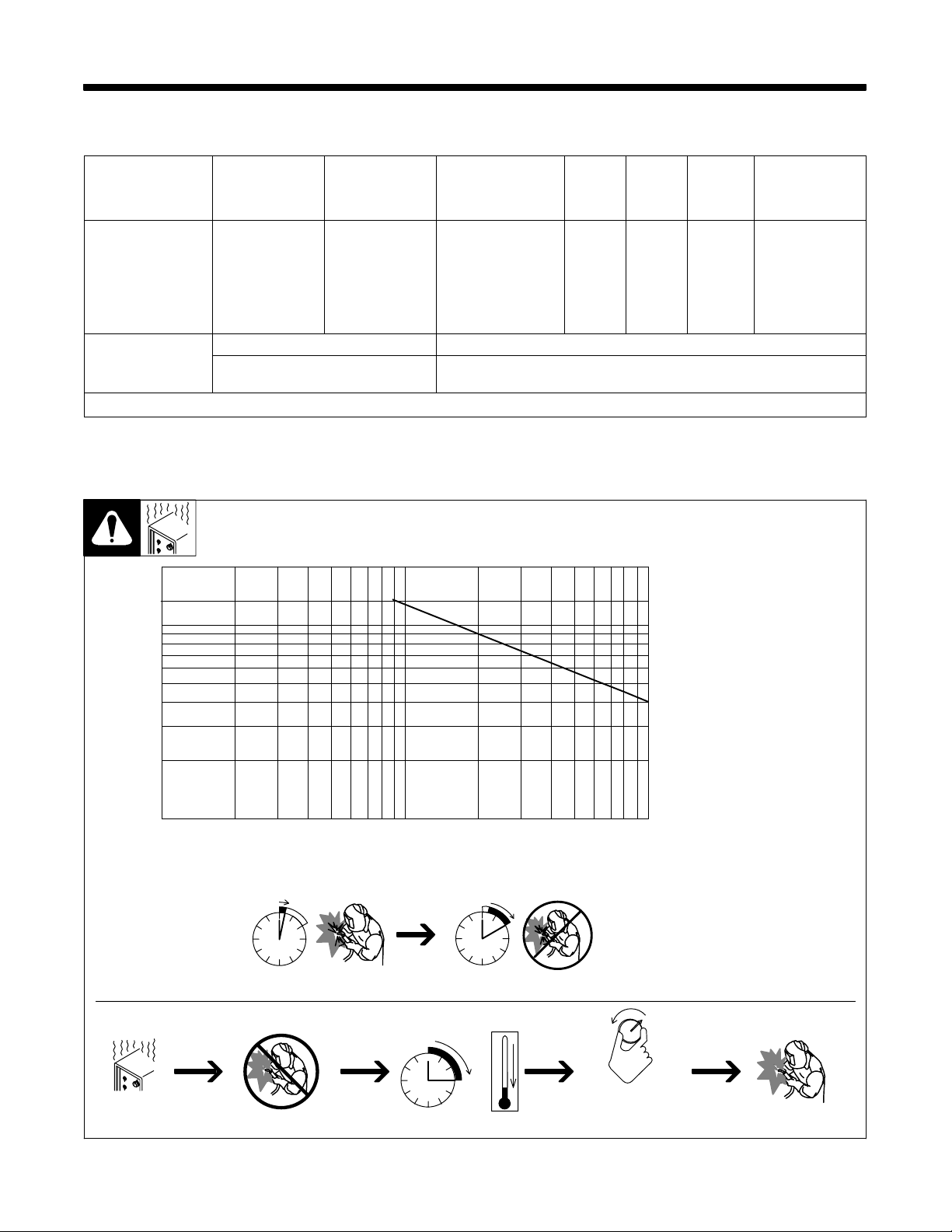
3-1. Specifications
SECTION 3 − SPECIFICATIONS
Rated Welding
Output
90 A @ 19 Volts DC,
20% Duty Cycle
63 A @ 21 Volts DC,
20% Duty Cycle*
Wire Type
And Dia
Maximum
Amperage
125
(0.8 − 0.9 mm)
Maximum Open-
Circuit Voltage
DC
29
Flux Cored Wire Feed Speed Range
.030 − .035 in
* CSA Rating
3-2. Duty Cycle And Overheating
200
135
100
80
60
Amperes Input at
Rated Load Output
115 V, 60 Hz, Single-
Phase
20
15*
183 − 295 IPM (4.6 − 7.5 m/min) At No Load
112 − 236 IPM (2.8 − 6.0 m/min) Feeding Wire
KVA KW
2.90
2.20*
2.50
1.77*
Weight
W/ Gun
50 lb
(22.7 kg)
Duty Cycle is percentage of 10 minutes that unit can weld at rated load
without overheating.
If unit overheats, thermostat(s)
opens, output stops, and cooling
fan runs. Wait fifteen minutes for
unit to cool. Reduce amperage or
duty cycle before welding.
NOTICE − Exceeding duty cycle
can damage unit or gun and void
warranty.
Overall
Dimensions
Length: 16-7/8 in
(429 mm)
Width: 9-7/8 in
(251 mm)
Height: 12-1/8 in
(308 mm)
40
Output Amperes
20
10
1
Overheating
4
2
68
10
20
Duty Cycle %
20% duty cycle at 90 amps
2 Minutes Welding 8 Minutes Resting
0
15
Minutes
40 60 100
A or V
OR
Reduce Duty Cycle
duty1 4/95 − 210 517-A
OM-923 Page 11
Page 16
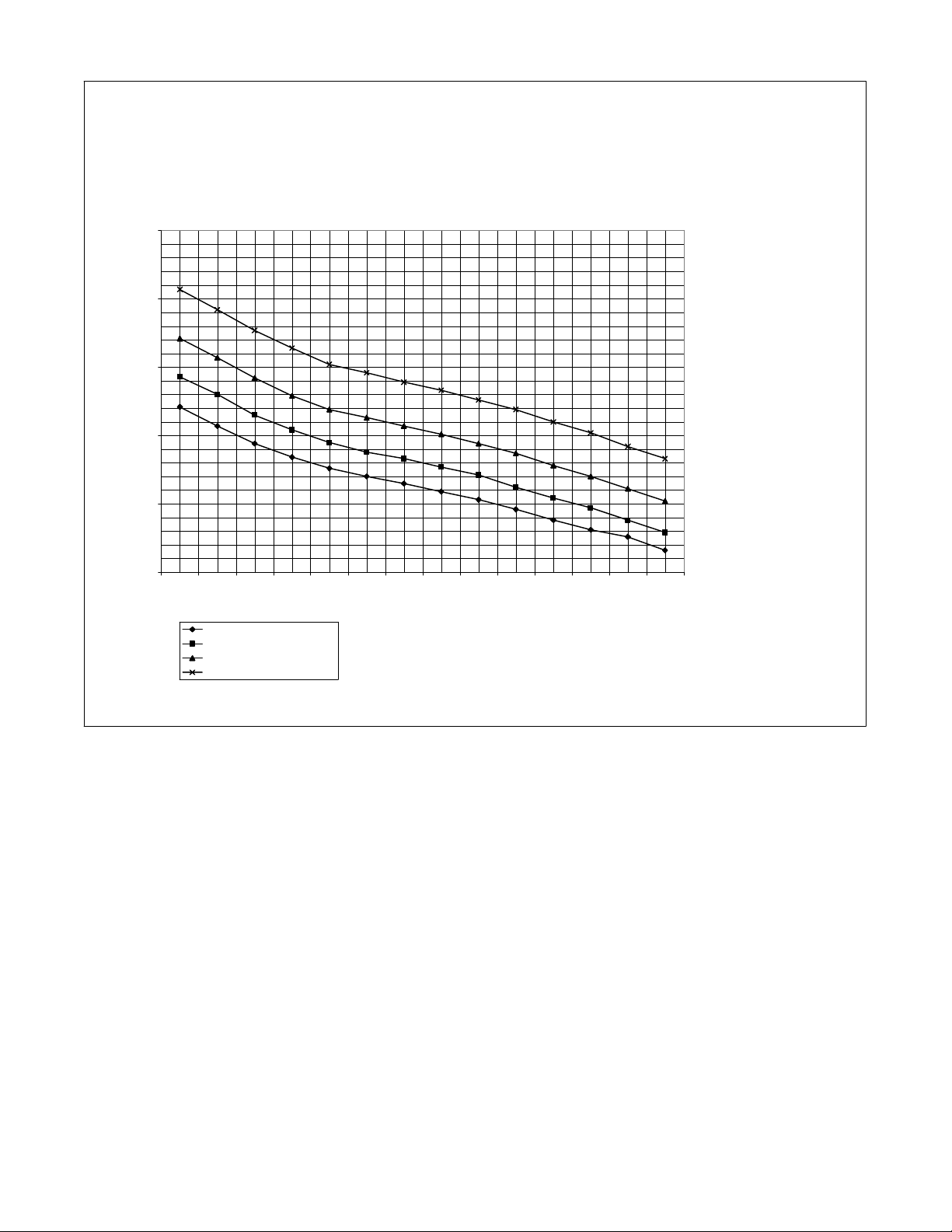
3-3. Volt-Ampere Curves
33. 0
28. 0
23. 0
Voltage
18. 0
13. 0
The volt-ampere curves show the
minimum and maximum voltage
and amperage output capabilities of
the welding power source. Curves
of other settings fall between the
curves shown.
8.0
0.0 10. 0 20. 0 30.0 40. 0 50. 0 60.0 70. 0 80. 0 90.0 100. 0 11 0.0 120. 0 13 0.0
Range 1
Range 2
Range 3
Range 4
(18-16 ga)
(16-12 ga)
(12-10 ga)
(10ga-3/16”)
Amperage
ssb1.1 10/91 − 210 519-A
OM-923 Page 12
Page 17
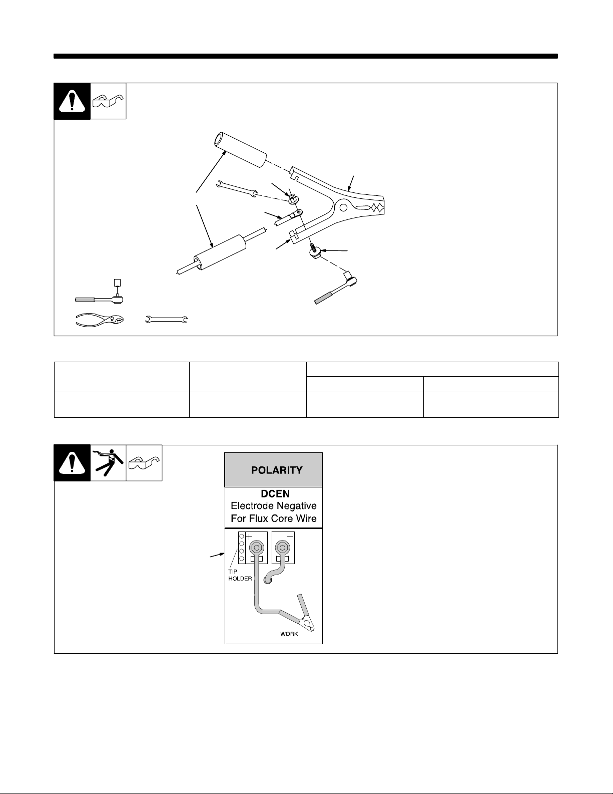
SECTION 4 − INSTALLATION
4-1. Installing Work Clamp
. Connection hardware must be tightened with proper tools. Do not just
hand tighten hardware. A loose electrical connection will cause poor
weld performance and excessive heating of the work clamp.
6
Tools Needed:
7/16 in
7/16 in
4-2. Process/Polarity Table
Process Polarity
FCAW − Self-shielding wire −
no shielding gas
DCEN − Straight Polarity Connect to negative (−)
1 Nut
2 Work Cable From Unit
3 Work Clamp
4 Screw
5 Work Clamp Tabs
Bend tabs around work cable.
1
2
5
3
4
Cable Connections
Cable To Gun Cable To Work Clamp
6 Insulator Grip
Slide one insulating grip over work
cable before connecting to clamp.
Slide insulating grips over handles.
Ref. 802 456
Connect to positive (+) output
output terminal
terminal
4-3. Polarity
. Polarity must be set for DCEN
(flux core wire) only.
1 Lead Connections For Direct
Current Electrode Negative
(DCEN)
Always read and follow wire
manufacturer’s recommended
polarity, and see Section 4-2.
Close door.
1
Ref. 210 428
OM-923 Page 13
Page 18
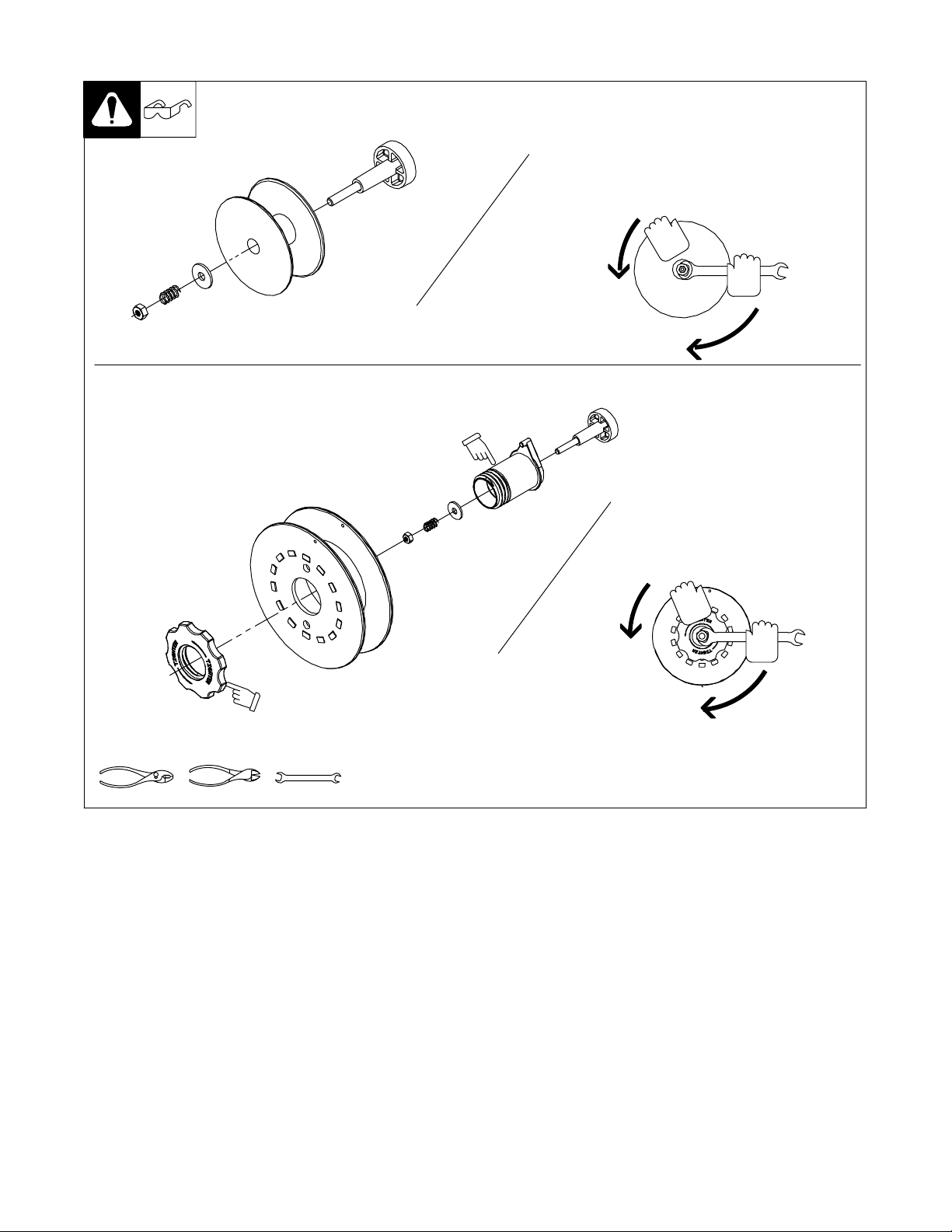
4-4. Installing Wire Spool And Adjusting Hub Tension
Installing 4 in (102 mm) Wire Spool
Installing 8 in (203 mm) Wire Spool
. Only applies to units equipped with
optional hub kit.
Adapter used with
8 in (203 mm)
spool only.
. Overtightening hub tension may
cause wire feed problems.
When a slight force is needed
to turn spool, tension is set.
Tools Needed:
When a slight force is needed
to turn spool, tension is set.
Retaining ring used
with 8 in (203 mm)
spool only.
1/2 in
Ref. 802 971-C / 803 012 / 803 013 -B
OM-923 Page 14
Page 19
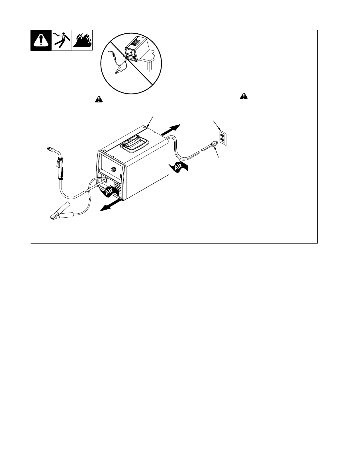
4-5. Selecting A Location And Connecting Input Power For 115 VAC Model
1 Rating Label
2 Grounded Receptacle
A 115 volt, 20 ampere individual
branch circuit protected by time-delay fuses or circuit breaker is required.
3 Plug From Unit
Select extension cord of 12 AWG
for up to 50 ft (15 m) or 10 AWG for
50 up to 100 ft (30 m).
! Do not move or operate unit
where it could tip.
1
18 in
(460 mm)
2
3
! Special installation may be
required where gasoline or
volatile liquids are present −
see NEC Article 511 or CEC
Section 20.
18 in
(460 mm)
804 122-C
OM-923 Page 15
Page 20
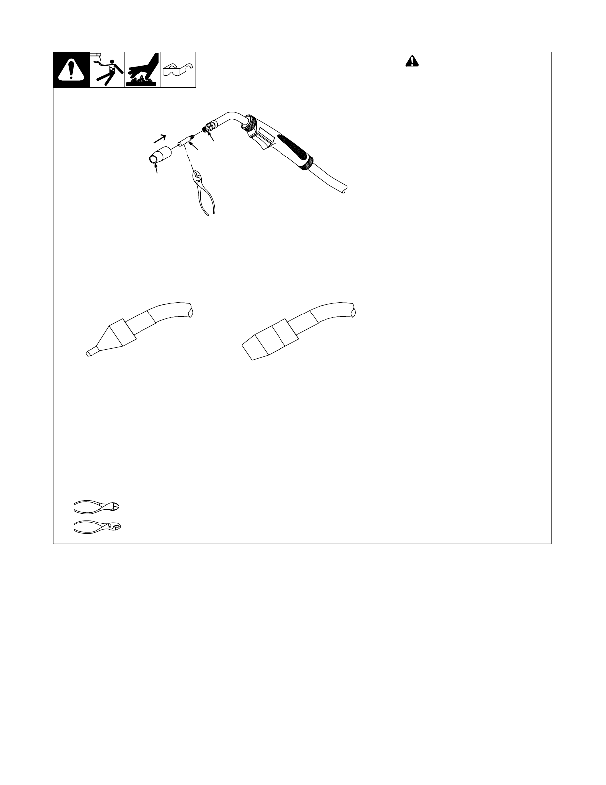
4-6. Installing Contact Tip And Nozzle
3
2
1
! Turn off welding power source.
1 Nozzle
Remove nozzle.
2 Contact Tip
3 Tip Adapter
Thread welding wire through gun (see
Section 4-7).
Slide contact tip over wire and tighten
tip into tip adapter.
Install nozzle.
Use with flux cored wire only.
Flux Nozzle MIG Nozzle
Narrow design allows access in
tight spaces and provides better
visibility of puddle during welding.
Push nozzle over contact tip and
adapter until it is seated onto
adapter. Contact tip will be
exposed approximately 7/16 in
(11.3 mm) when installed properly.
Tools Needed:
Use with solid or flux cored wire.
Push nozzle over contact tip and
adapter until it is seated onto
adapter. End of contact tip will be
flush with end of nozzle when
installed properly.
Ref. 804 241-A
OM-923 Page 16
Page 21
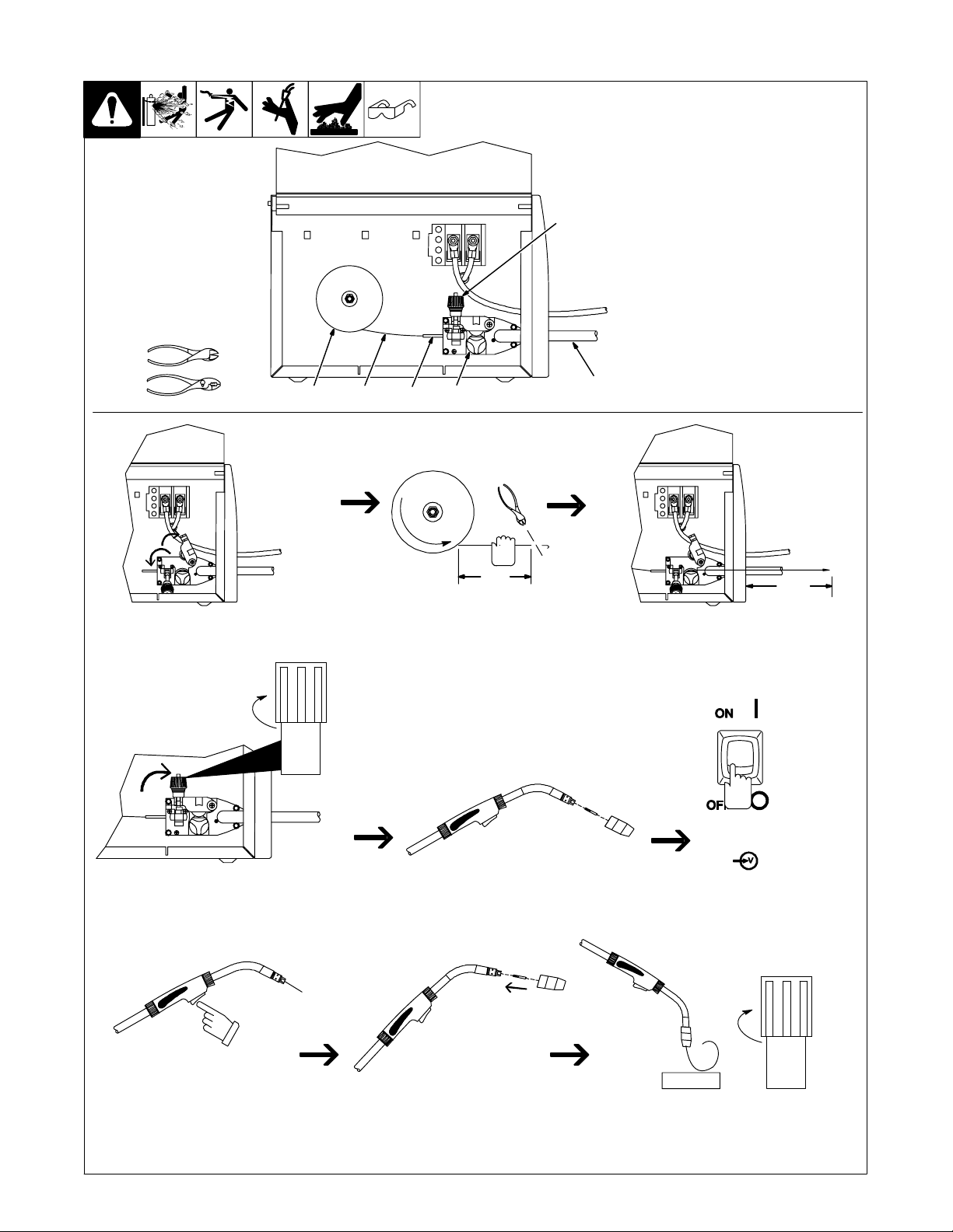
4-7. Threading Welding Wire
Tools Needed:
1 Wire Spool
2 Welding Wire
3 Inlet Wire Guide
4 Pressure Adjustment Knob
5 Drive Roll
6 Gun Cable
−+
4
Lay gun cable out straight.
123
5
6
. Hold wire tightly to keep it
from unraveling.
+ −
6 in
(150 mm)
Open pressure assembly. Push wire thru guides into gun liner;
Pull and hold wire; cut off end.
+ −
(102 mm)
continue to hold wire.
4 in
. Loosen knob completely, then rotate
Tighten
pressure adjustment knob in a
clockwise direction until drive roll is
tight against the welding wire.
Adjust drive roll pressure just
tightly enough to prevent wire
from slipping against drive roll
during operation.
INPUT
POWER
Be sure that wire is positioned
in proper feed roll groove.
Close and tighten pressure
assembly, and let go of wire.
Press gun trigger until wire comes
out of gun.
Remove gun nozzle and contact tip.
. Tip adapter may also require removal
to allow wire to feed out end of gun.
Be sure that contact tip matches wire diameter.
Reinstall tip adapter, if applicable, contact tip
and nozzle.
Turn power on.
Tighten
WOOD
Feed wire to check drive roll pressure.
Tighten knob enough to prevent slipping.
Cut off wire. Close door.
804 123-A
OM-923 Page 17
Page 22
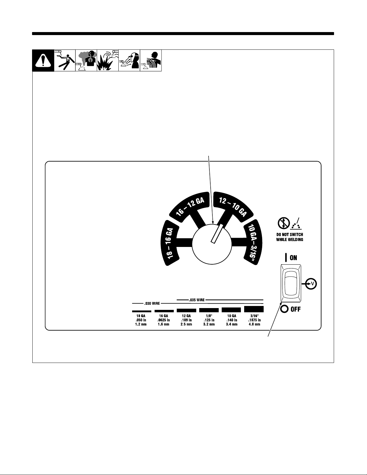
5-1. Controls
SECTION 5 − OPERATION
1 Material Thickness Selector
Switch
Use switch to select the material
thickness range. Do not switch
under load.
. Switch must “click” into detent
position for weld output.
2 Power Switch
1
OM-923 Page 18
2
Ref. 230 001-A
Page 23
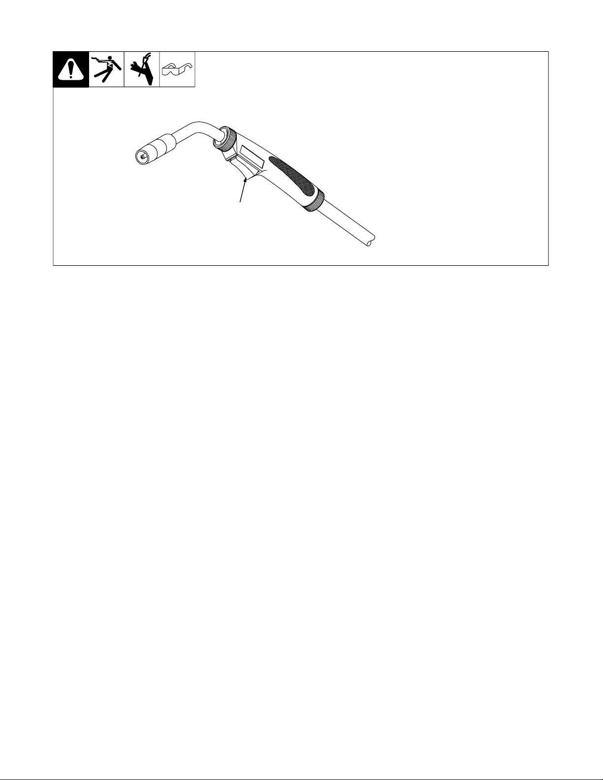
5-2. Operating The Gun
1 Trigger Switch
When pressed, energized wire
feeds.
1
Ref. 804 240-A
OM-923 Page 19
Page 24
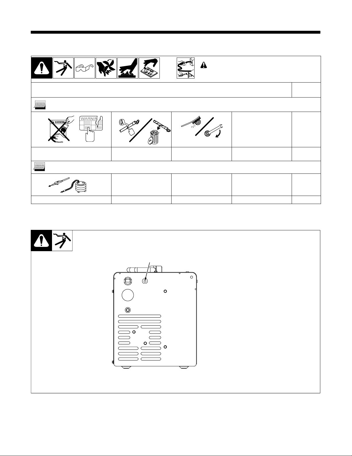
SECTION 6 − MAINTENANCE &TROUBLESHOOTING
6-1. Routine Maintenance
n = Check Z = Change ~ = Clean l = Replace
* To be done by Factory Authorized Service Agent
3 Months
l Damaged Or Unreadable Labels l Repair Or Replace
Cracked Weld Cable
6 Months
OR
~ Inside Unit
6-2. Overload Protection
! Disconnect power
before maintaining.
~ Clean And Tighten Weld
Terminals
. Maintain more often
during severe conditions.
Reference
1 Supplementary Protector CB1
CB1 protects unit from overload. If
CB1 opens, unit shuts down.
1
Reset supplementary protector.
804 127-A
6-3. Drive Motor Protection
Drive motor protection circuit protects drive motor from overload. If drive motor becomes inoperative, release gun
trigger and wait until protection circuit resets allowing drive motor to feed wire again.
OM-923 Page 20
Page 25
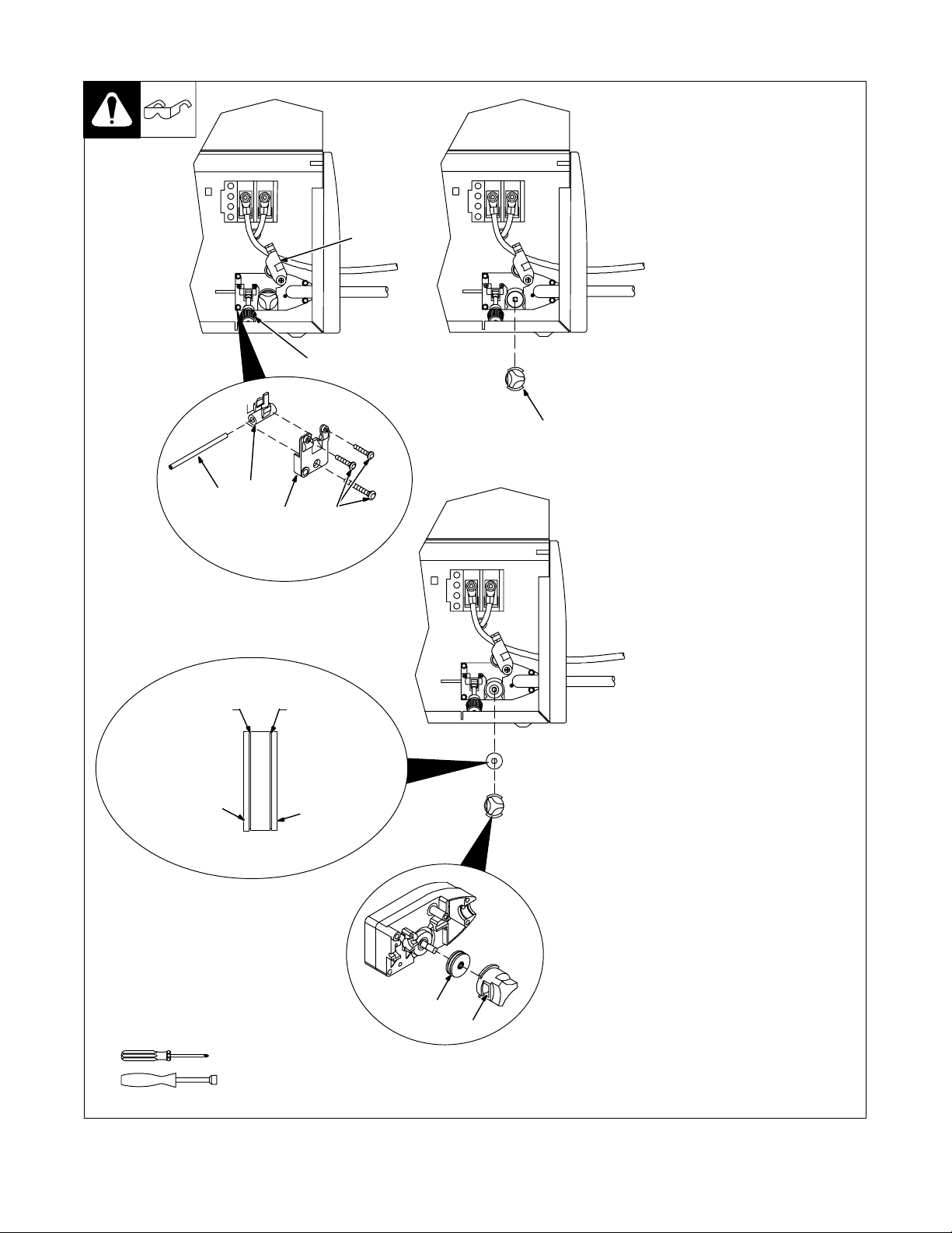
6-4. Changing Drive Roll Or Wire Inlet Guide
+ −
2
1
5
6
3
.030/.035
VK Groove
4
+
.024 Groove
+ −
−
1 Pressure Adjustment Knob
2 Pressure Assembly
Pivot pressure adjustment knob
down, and lift pressure assembly
up.
3 Pivot Tube Plate
4 Securing Screws
5 Pressure Arm Pivot Tube
6 Inlet Wire Guide
Remove screws and pivot tube
plate. Lift out pressure arm pivot
tube, and slide inlet wire guide out of
tube.
Slide replacement wire guide into
tube, and place tube back into drive
assembly. Be sure tip of wire guide
is as close to drive roll as possible
without touching.
Reinstall plate and tighten screws.
7
7 Retaining Knob
Rotate counterclockwise and
remove knob.
8 Drive Roll
The drive roll consists of two
different sized grooves. Each side
is stamped with the proper size.
Select the groove that matches the
wire size on the wire spool. Install
drive roll onto motor shaft so that
correct groove size stamp faces out
away from drive housing.
9 Retaining Knob Opening
Install retaining knob by placing
opening over drive roll (opening
faces rear of unit). Rotate retaining
knob clockwise to secure drive roll.
Position wire into outer groove of
drive roll (see Section 4-7).
Stamped .030/.035
Tools Needed:
Stamped .024
8
9
5/16 in
804 123-A / 804 129-A
OM-923 Page 21
Page 26
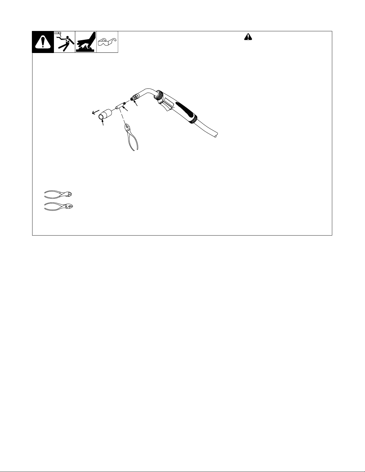
6-5. Replacing Gun Contact Tip
3
2
1
Tools Needed:
! Turn Off power before replacing
contact tip.
1 Nozzle
Remove nozzle.
2 Contact Tip
3 Tip Adapter
Cut off welding wire at contact tip.
Remove contact tip from tip adapter,
and install new contact tip. Reinstall
nozzle.
Ref. 804 241-A
OM-923 Page 22
Page 27
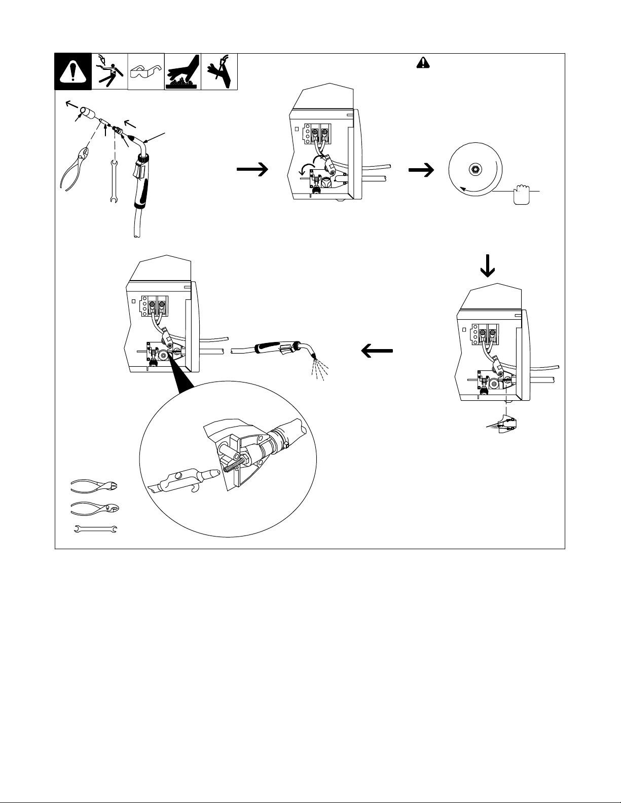
6-6. Cleaning Gun Liner
1
2
3
8 mm
Head
Tube
Remove nozzle. Cut off wire
at contact tip, and remove
contact tip and tip adapter.
−
+
+ −
Open pressure assembly. Retract
wire from liner onto spool.
! Turn Off welding power source.
1 Nozzle
2 Contact Tip
3 Adapter
. Hold wire tightly to keep it
from unraveling. Secure
end of wire at spool.
+ −
Tools Needed:
8 mm
Lay gun cable out straight,
and blow out liner.
Remove screws (3) from
cover, and remove cover
from wire drive assembly.
Reassemble drive cover
and gun in reverse order
from taking it apart.
. Thread wire according to
Section 4-7.
804 241-A / Ref. 804 123-A / 804 128-A / Ref. 803 837-A
OM-923 Page 23
Page 28
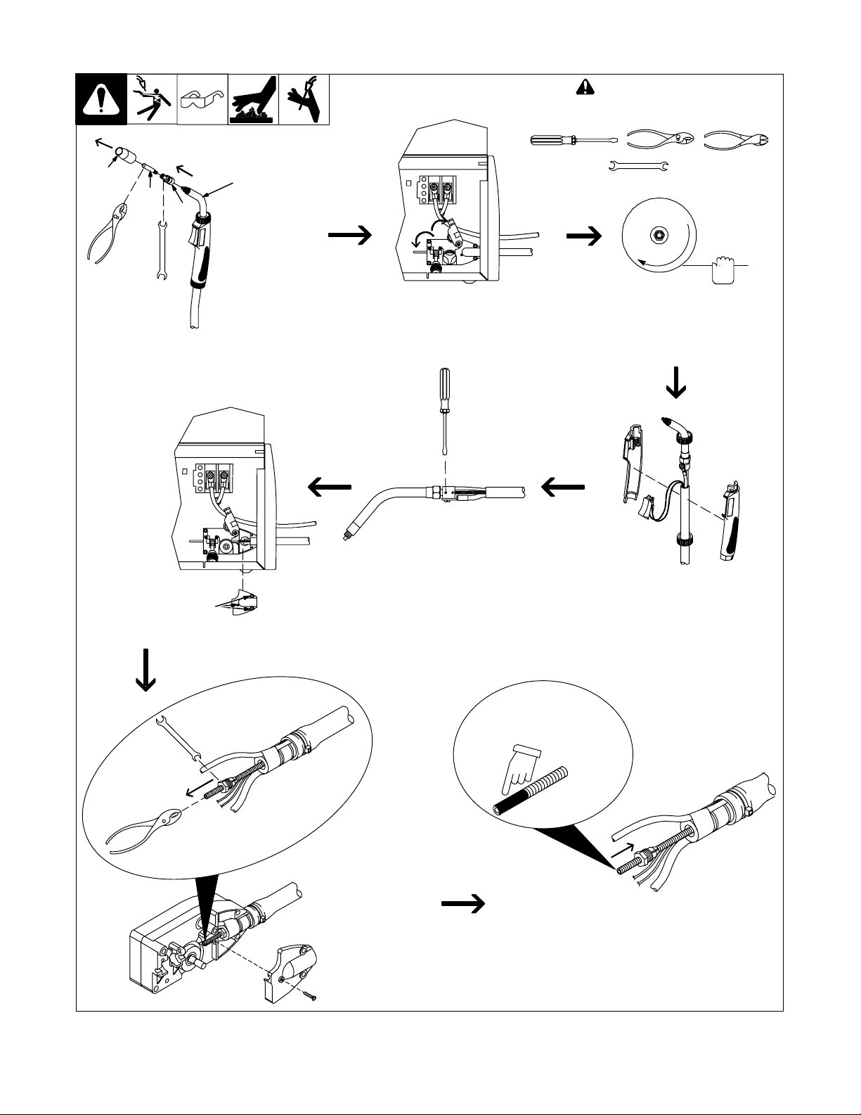
6-7. Replacing Gun Liner
! Turn Off welding power source.
Tools Needed:
1
2
3
8 mm
Head
Tube
Remove nozzle. Cut off wire
at contact tip, and remove
contact tip and tip adapter.
+ −
+ −
Open pressure assembly. Retract
wire from liner onto spool.
. Hold wire tightly to keep it
8 mm / 10 mm
from unraveling. Secure
end of wire at spool.
Remove screws (3) from
cover, and remove cover
from wire drive assembly.
8 mm
Loosen liner setscrew.
Loosen and remove
retaining nut from liner.
Pull liner out of gun
cable. If necessary, twist
cable to ease removal.
Twist top and bottom handle locking rings
counterclockwise 1/4 turn. Slide bottom ring
down cable and top ring forward over head
tube. Separate gun handle halves.
Remove black sleeving from
end of replacement liner.
Install retaining nut on one end of liner. Lay
gun cable straight on a flat surface. Insert
bare end of liner (end without retaining nut)
into wire drive end of cable. Push liner
toward gun. If necessary, twist cable to
ease installation.
Ref. 804 241-A / 804 123-A / 803 837-A / 803 899-A
OM-923 Page 24
Page 29
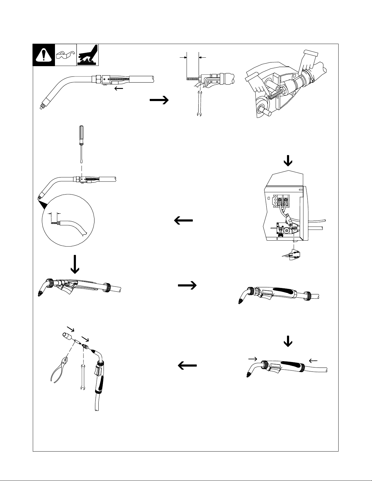
6-7. Replacing Gun Liner (Continued)
13/16 in
(21 mm)
When liner exits cable at gun
handle, guide liner into head
tube. Continue to push liner until
it exits end of head tube.
3/8 in (10 mm)
8 mm
Insert retaining nut into adapter, and adjust liner stickout as
shown. Tighten retaining nut. Reinstall cable end into drive
housing with retaining grooves inserted into the two retaining
ribs. Be sure to position gas hose up. Position liner in groove
so that end is flush with back of groove, adjust if necessary
+ −
Be sure that cable is straight.
Tighten liner setscrew. Cut
liner so that 3/8 in (10 mm)
sticks out of head tube. File
down any sharp points on
liner after cutting to length.
Reinstall cover onto wire
drive assembly, and secure
with screws (3).
Reassemble gun by placing head tube
and cable into one half of handle. Be
sure trigger is properly installed into
trigger slot.
8 mm
Thread welding wire through
gun (see Section 4-7). Reinstall
adapter, contact tip, and nozzle.
Place other half of handle over
head tube and cable.
Slide locking rings over top and
bottom of handle, and secure by
twisting rings clockwise 1/4 turn.
OM-923 Page 25
Page 30
6-8. Troubleshooting Table
Trouble Remedy
Electrode wire feeding stops during
welding.
No weld output; wire does not feed; fan
does not run.
Straighten gun cable and/or replace damaged parts.
Adjust drive roll pressure (see Section 4-7).
Change to proper drive roll groove (see Section 6-4).
Readjust hub tension (see Section 4-4).
Replace contact tip if blocked (see Section 6-5).
Clean or replace wire inlet guide or liner if dirty or plugged (see Section 6-4).
Replace drive roll or pressure bearing if worn or slipping (see Section 6-4).
Check and clear any restrictions at drive assembly and liner (see Section 4-7).
Release gun trigger and allow gun and motor protection circuitry to reset.
Have nearest Factory Authorized Service Agent check drive motor.
Secure power cord plug in receptacle (see Section 4-5).
Replace building line fuse or reset circuit breaker if open.
Place Power switch in On position (see Section 5-1).
Reset welding power source supplementary protector if open.
No weld output; wire does not feed; fan
motor continues to run.
No weld output; wire feeds.
Low weld output.
Thermostat TP1 open (overheating). Allow fan to run with gun trigger switch off; thermostat resets when
unit has cooled (see Section 3-2).
Be sure that Material Thickness Selector switch is not set between ranges (see Section 5-1).
Disassemble torch handle and check trigger switch lead connections, tighten or reconnect any loose
connections.
Connect work clamp to get good metal to metal contact.
Check cable connection at work clamp and tighten hardware, if necessary (see Section 4-1).
Replace contact tip (see Section 6-5).
Connect unit to proper input voltage or check for low line voltage.
Place Material Thickness Selector switch in correct setting (see Section 5-1).
If using an extension cord, check that wire size and length is the proper size for power rating of welding
power source (see Section 3-1).
OM-923 Page 26
Page 31
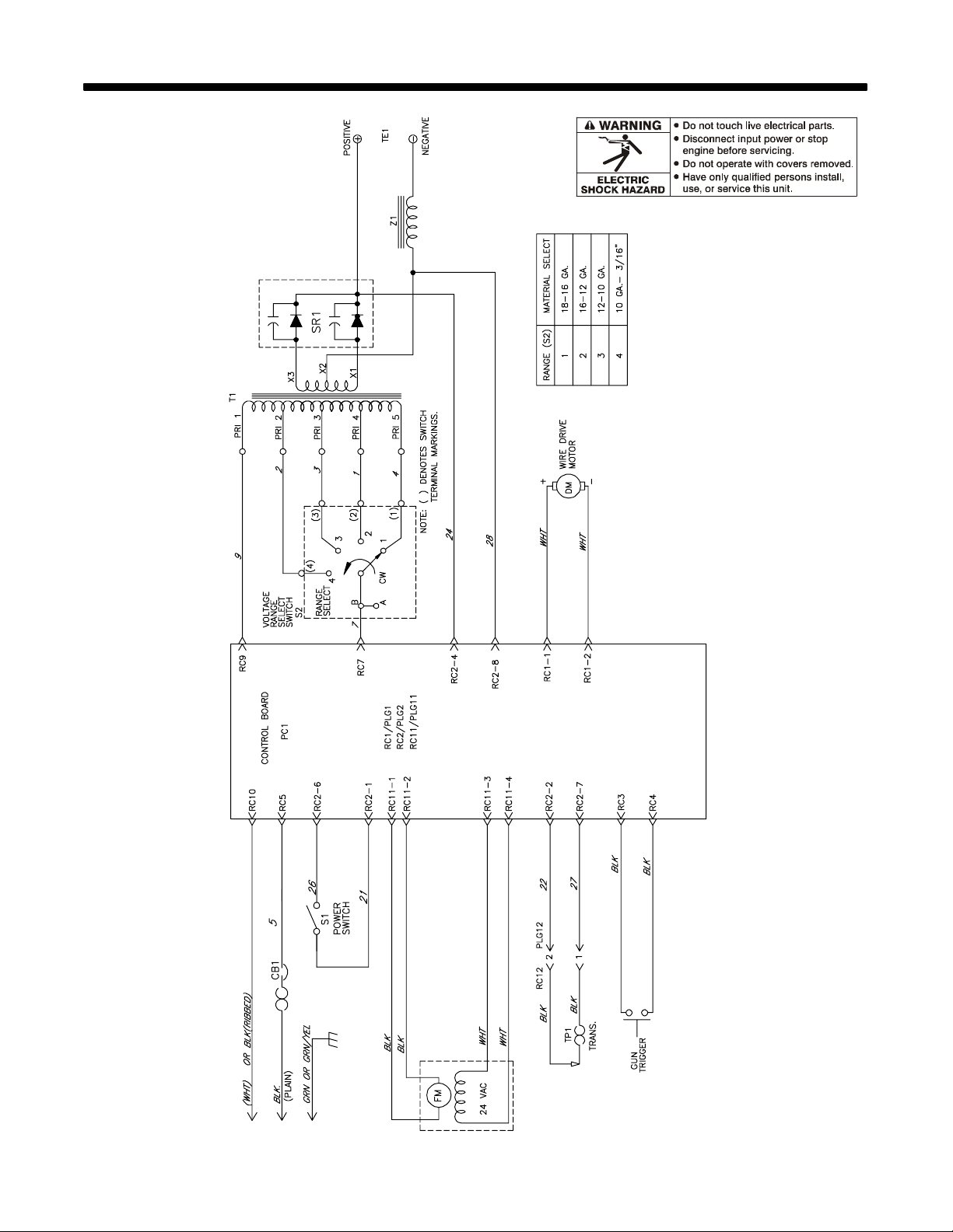
SECTION 7 − ELECTRICAL DIAGRAM
Figure 7-1. Circuit Diagram
230 951-A
OM-923 Page 27
Page 32
SECTION 8 − WIRE WELDING GUIDELINES
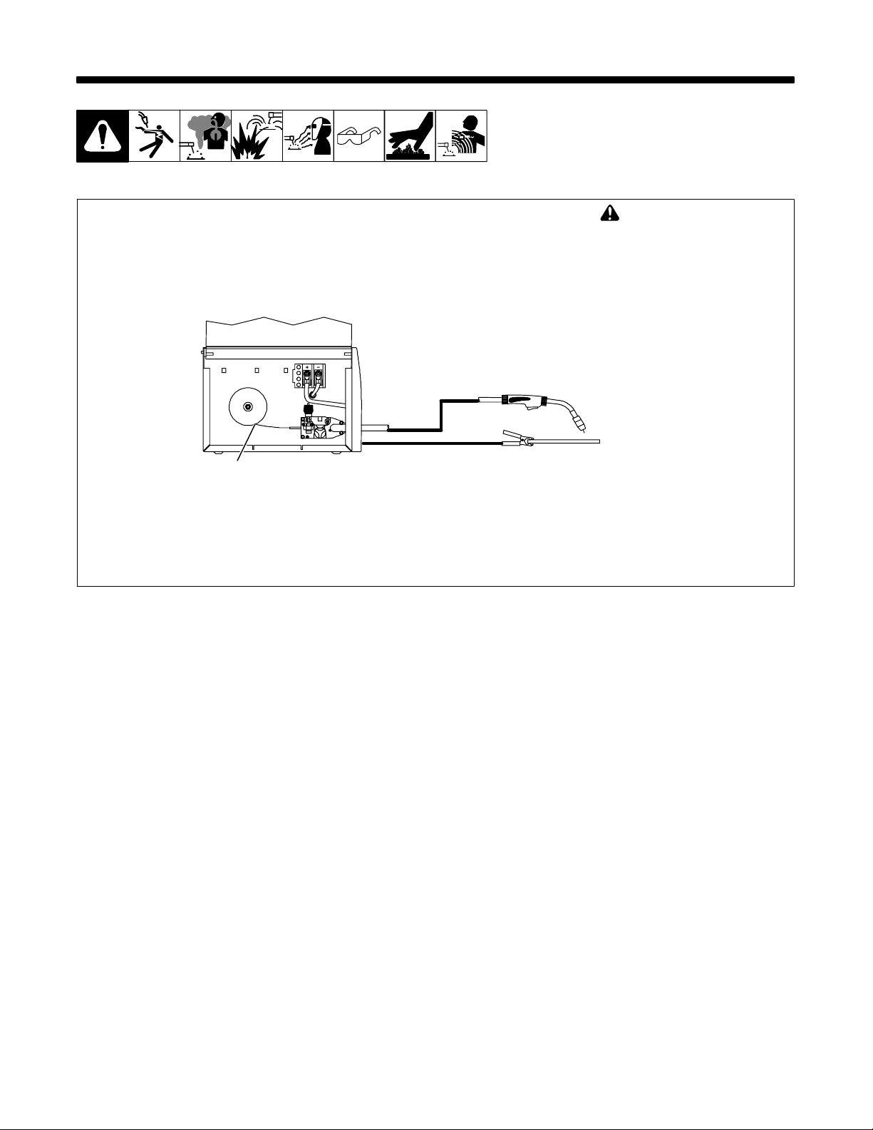
8-1. Typical FCAW Process Connections
Wire Feeder/
Power Source
! Weld current can damage
electronic parts in vehicles.
Disconnect both battery
cables before welding on a
vehicle. Place work clamp as
close to the weld as possible.
Gun
Self-Shielding Flux
Core Wire
Work Clamp
Workpiece
fcaw 1/2003 / Ref. 803 444-A
OM-923 Page 28
Page 33
8-2. Typical Control Settings
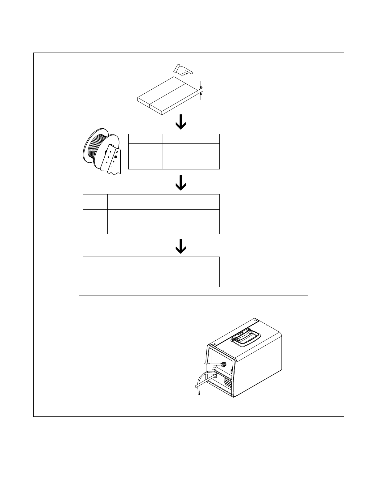
. These settings are guidelines only. Material and wire type, joint design, fitup, position, shielding gas, etc. affect settings. Test welds to be sure
they comply to specifications.
Material thickness determines weld
parameters.
1/8 or 0.125 in
Convert Material
Thickness to
Amperage (A)
(0.001 in = 1 ampere)
0.125 in = 125 A
.035 in
Wire
Size
0.023 in
0.030 in
0.035 in
Recommendation
3.5 in per ampere
2 in per ampere
1.6 in per ampere
Low voltage: wire stubs into work
High voltage: arc is unstable (spatter)
Set voltage midway between high/low voltage
Wire Size Amperage Range
0.023 in
0.030 in
0.035 in
30 − 90 A
40 − 145 A
50 − 180 A
Wire Speed
(Approx.)
3.5 x 125 A = 437 ipm
2 x 125 A = 250 ipm
1.6 x 125 A = 200 ipm
Select Wire Size
Select Wire Speed
(Amperage)
125 A based on 1/8 in
material thickness
ipm = inches per minute
Select Voltage
Metal thickness select will control
both voltage and wire feed speed by
selecting metal thickness.
Ref. 804 121-C
OM-923 Page 29
Page 34
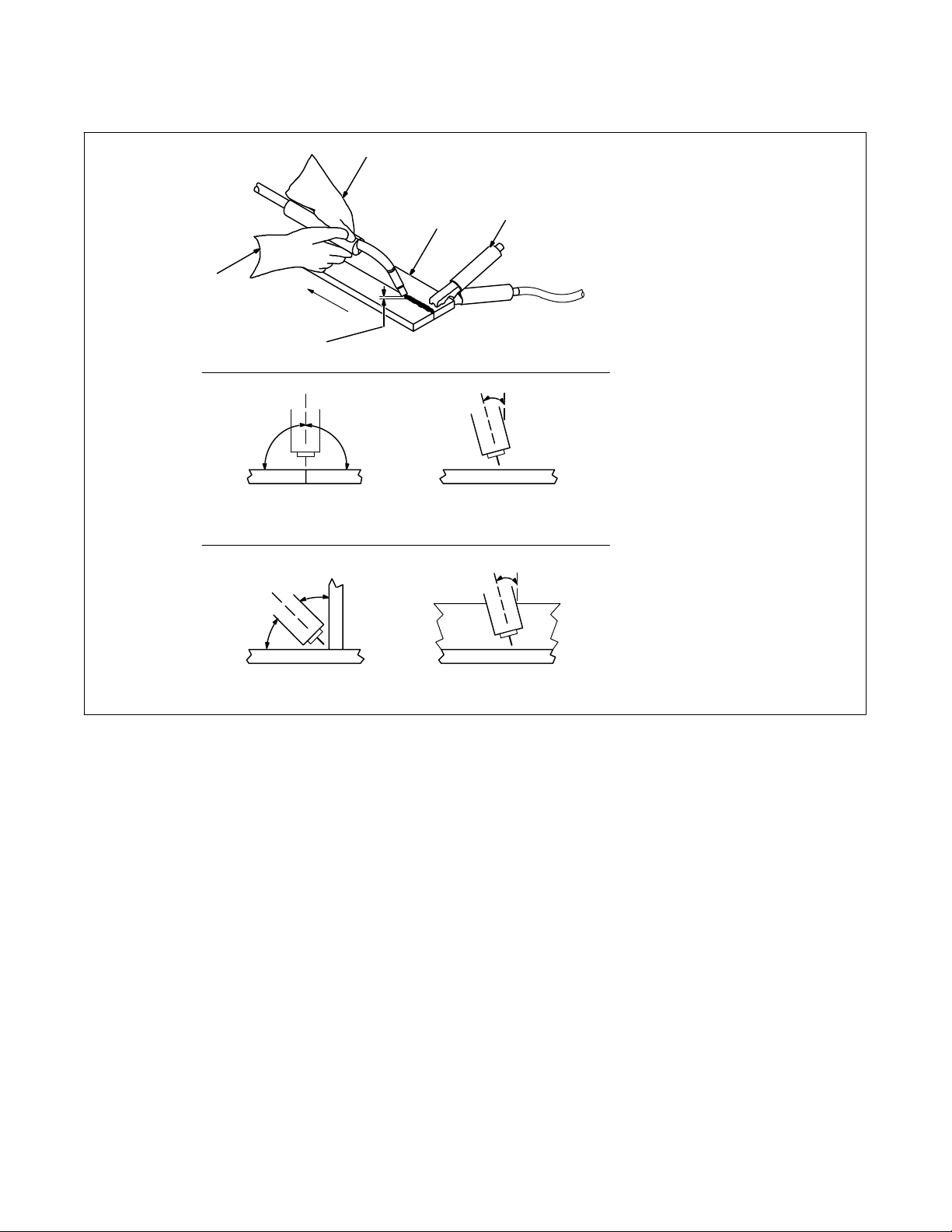
8-3. Holding And Positioning Welding Gun
. Welding wire is energized when gun trigger is pressed. Before lowering helmet and pressing trigger, be sure wire is no more than 1/2 in (13 mm)
past end of nozzle, and tip of wire is positioned correctly on seam.
1
2
5
Drag
4
0°-15°
90° 90°
End View of Work Angle Side View of Gun Angle
GROOVE WELDS
45°
0°-15°
1 Hold Gun and Control Gun
Trigger
2 Workpiece
3
3 Work Clamp
4 Electrode Extension (Stickout)
1/4 to 1/2 in (6 To 13 mm)
5 Cradle Gun and Rest Hand on
Workpiece
45°
End View of Work Angle Side View of Gun Angle
FILLET WELDS
S-0421-A
OM-923 Page 30
Page 35
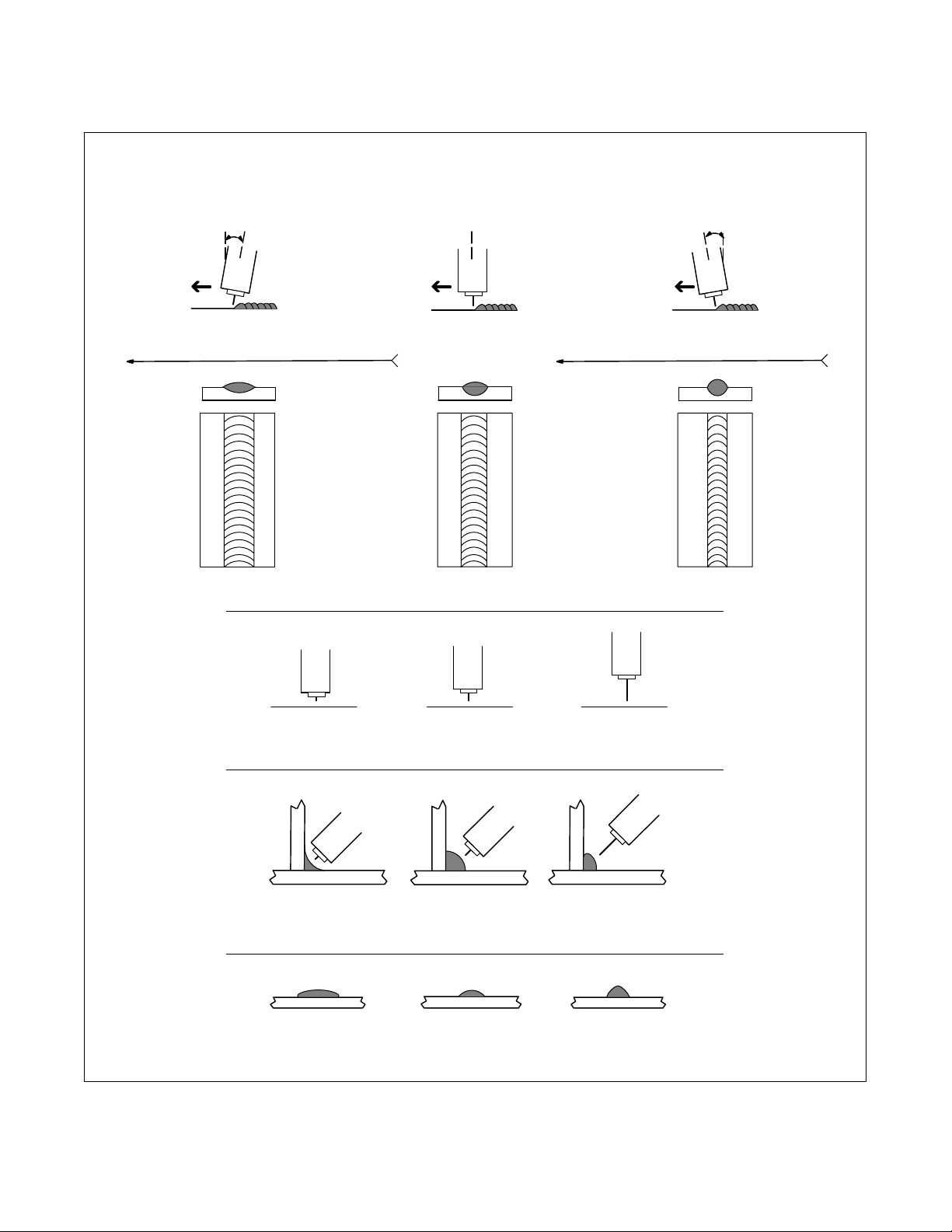
8-4. Conditions That Affect Weld Bead Shape
. Weld bead shape depends on gun angle, direction of travel, electrode extension (stickout), travel speed, thickness of base metal, wire feed speed
(weld current), and voltage.
. The Drag or Pull technique is generally recommended when welding with flux-cored tubular wire.
Push Perpendicular Drag or Pull
10°
10°
Electrode directed
ahead of bead
Electrode pointed
back into bead
Direction Of Welding
GUN ANGLES AND WELD BEAD PROFILES
Short Normal Long
ELECTRODE EXTENSIONS (STICKOUT)
Short Normal Long
FILLET WELD ELECTODE EXTENSIONS (STICKOUT)
Slow
Normal Fast
GUN TRAVEL SPEED
S-0634
OM-923 Page 31
Page 36
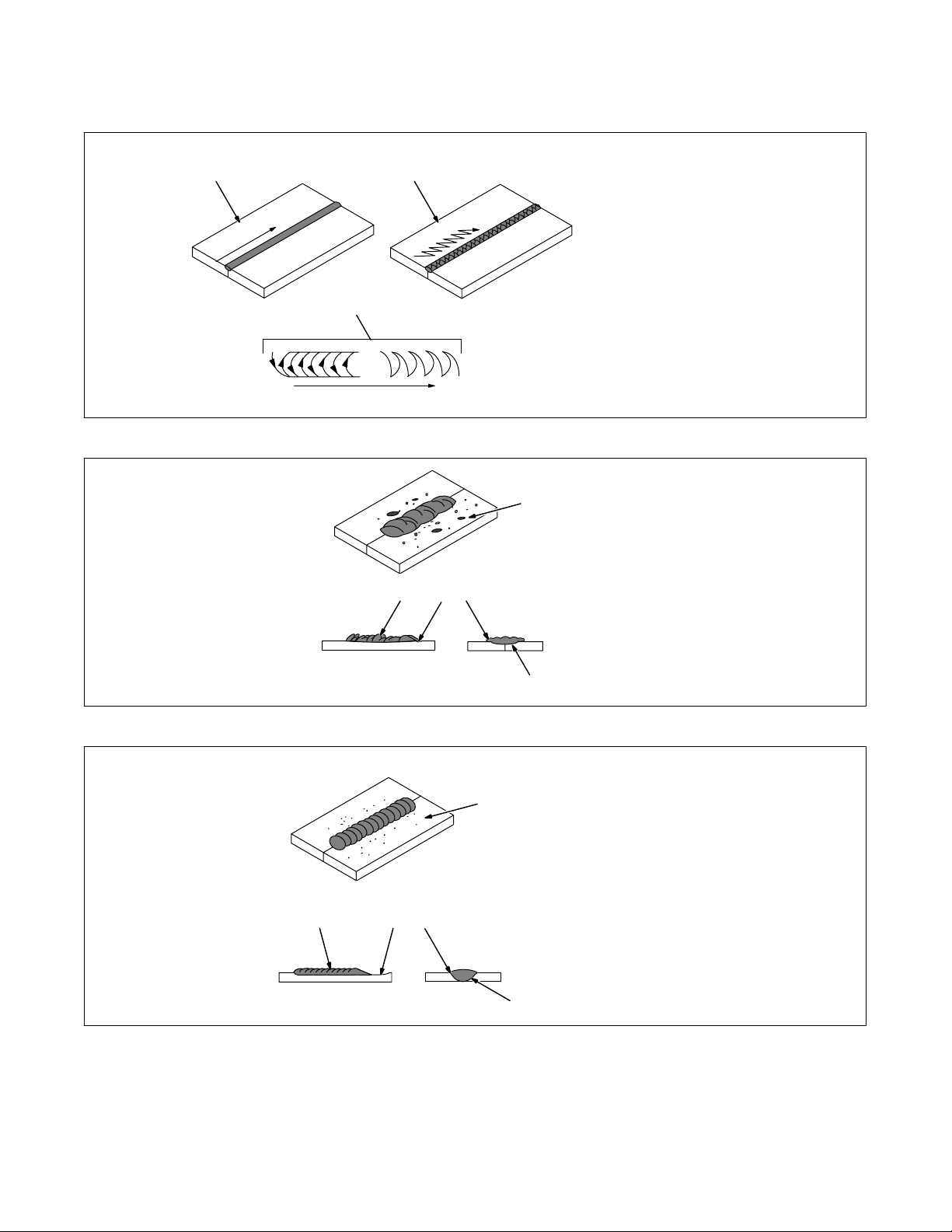
8-5. Gun Movement During Welding
. Normally, a single stringer bead is satisfactory for most narrow groove weld joints; however, for wide groove weld joints or bridging across gaps,
a weave bead or multiple stringer beads works better.
1 Stringer Bead − Steady
1 2
3
Movement Along Seam
2 Weave Bead − Side To Side
Movement Along Seam
3 Weave Patterns
Use weave patterns to cover a wide
area in one pass of the electrode.
S-0054-A
8-6. Poor Weld Bead Characteristics
1 Large Spatter Deposits
1
2 Rough, Uneven Bead
3 Slight Crater During Welding
4 Bad Overlap
5 Poor Penetration
2
8-7. Good Weld Bead Characteristics
2
4
3
4
3
5
1 Fine Spatter
2 Uniform Bead
1
5
3 Moderate Crater During
Welding
Weld a new bead or layer for each
1/8 in (3.2 mm) thickness in metals
being welded.
4 No Overlap
5 Good Penetration into Base
Metal
S-0053-A
S-0052-B
OM-923 Page 32
Page 37
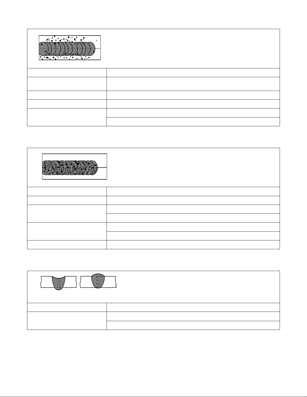
8-8. Troubleshooting − Excessive Spatter
Excessive Spatter − scattering of molten metal particles that
cool to solid form near weld bead.
Possible Causes Corrective Actions
S-0636
Metal Thickness Selector switch set too
high.
Electrode extension (stickout) too long. Use shorter electrode extension (stickout).
Workpiece dirty. Remove all grease, oil, moisture, rust, paint, undercoating, and dirt from work surface before welding.
Dirty welding wire. Use clean, dry welding wire.
Set Metal Thickness Selector switch to a lower selection.
Eliminate pickup of oil or lubricant on welding wire from feeder or liner.
8-9. Troubleshooting − Porosity
Porosity − small cavities or holes resulting from gas pockets
in weld metal.
S-0635
Possible Causes Corrective Actions
Wrong gas. Use welding grade shielding gas; change to different gas.
Dirty welding wire. Use clean, dry welding wire.
Eliminate pick up of oil or lubricant on welding wire from feeder or liner.
Workpiece dirty. Remove all grease, oil, moisture, rust, paint, coatings, and dirt from work surface before welding.
Use a more highly deoxidizing welding wire (contact supplier).
Welding wire extends too far out of nozzle. Be sure welding wire extends not more than 1/2 in (13 mm) beyond nozzle.
8-10. Troubleshooting − Excessive Penetration
Excessive Penetration − weld metal melting through base metal
and hanging underneath weld.
Excessive Penetration
Possible Causes Corrective Actions
Excessive heat input. Set Metal Thickness Selector switch to a lower selection.
Good Penetration
Increase travel speed.
S-0639
OM-923 Page 33
Page 38
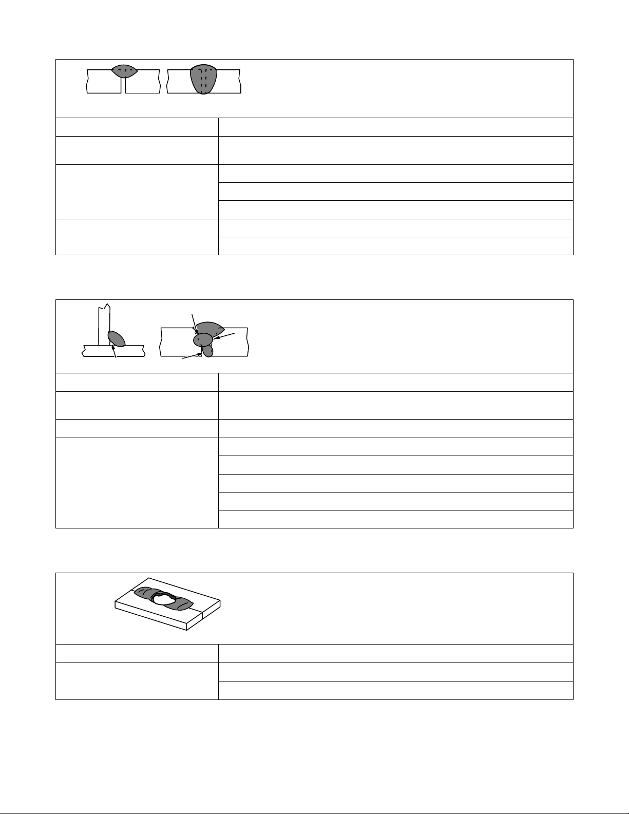
8-11. Troubleshooting − Lack Of Penetration
Lack Of Penetration − shallow
fusion between weld metal and
base metal.
Lack of Penetration Good Penetration
Possible Causes Corrective Actions
S-0638
Improper joint preparation. Material too thick. Joint preparation and design must provide access to bottom of groove while
maintaining proper welding wire extension and arc characteristics.
Improper weld technique. Maintain normal gun angle of 0 to 15 degrees to achieve maximum penetration.
Keep arc on leading edge of weld puddle.
Be sure welding wire extends not more than 1/2 in (13 mm) beyond nozzle.
Insufficient heat input. Set Metal Thickness Selector switch to a higher selection.
Reduce travel speed.
8-12. Troubleshooting − Incomplete Fusion
Incomplete Fusion − failure of weld metal to fuse completely with
base metal or a preceeding weld bead.
Possible Causes Corrective Actions
Workpiece dirty. Remove all grease, oil, moisture, rust, paint, undercoating, and dirt from work surface before
welding.
Insufficient heat input. Set Metal Thickness Selector switch to a higher selection.
S-0637
Improper welding technique. Place stringer bead in proper location(s) at joint during welding.
Adjust work angle or widen groove to access bottom during welding.
Momentarily hold arc on groove side walls when using weaving technique.
Keep arc on leading edge of weld puddle.
Use correct gun angle of 0 to 15 degrees.
8-13. Troubleshooting − Burn-Through
Burn-Through − weld metal melting completely through base metal
resulting in holes where no metal remains.
Possible Causes Corrective Actions
Excessive heat input. Set Metal Thickness Selector switch to a lower selection.
Increase and/or maintain steady travel speed.
S-0640
OM-923 Page 34
Page 39
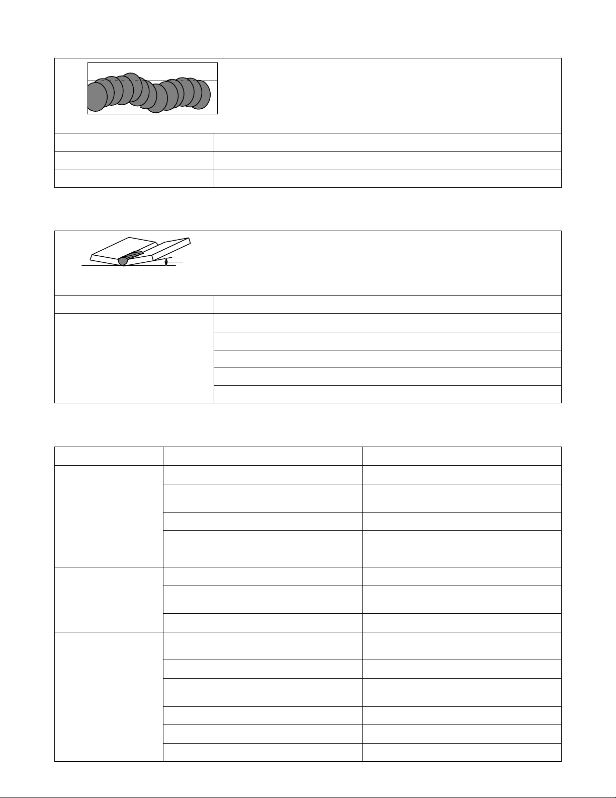
8-14. Troubleshooting − Waviness Of Bead
Waviness Of Bead − weld metal that is not parallel and does not cover
joint formed by base metal.
Possible Causes Corrective Actions
Welding wire extends too far out of nozzle. Be sure welding wire extends not more than 1/2 in (13 mm) beyond nozzle.
Unsteady hand. Support hand on solid surface or use two hands.
8-15. Troubleshooting − Distortion
Distortion − contraction of weld metal during welding that forces
base metal to move.
Base metal moves
in the direction of
the weld bead.
Possible Causes Corrective Actions
Excessive heat input. Use restraint (clamp) to hold base metal in position.
S-0641
S-0642
Make tack welds along joint before starting welding operation.
Set Metal Thickness Selector switch to a lower selection.
Increase travel speed.
Weld in small segments and allow cooling between welds.
8-16. Troubleshooting Guide For Semiautomatic Welding Equipment
Problem Probable Cause Remedy
Wire feed motor operates, but
wire does not feed.
Wire curling up in front of the
wire feed rolls (bird nesting).
Too little pressure on wire feed rolls. Increase pressure setting on wire feed rolls.
Incorrect wire feed rolls. Check size stamped on wire feed rolls, replace to match
wire size and type if necessary.
Wire spool brake pressure too high. Decrease brake pressure on wire spool.
Restriction in the gun and/or assembly. Check and replace cable, gun, tip adapter, and contact
tip if damaged. Check size of contact tip and cable liner,
replace if necessary.
Too much pressure on wire feed rolls. Decrease pressure setting on wire feed rolls.
Incorrect cable liner or gun contact tip size. Check size of contact tip and check cable liner length
and diameter, replace if necessary.
Dirty or damaged (kinked) liner. Replace liner.
Welding arc not stable.
Wire slipping in drive rolls. Adjust pressure setting on wire feed rolls. Replace worn
Wrong size gun liner or contact tip. Match liner and contact tip to wire size and type.
Incorrect Metal Thickness Selector switch setting on
welding power source.
Loose connections at the gun weld cable or work cable. Check and tighten all connections.
Gun in poor shape or loose connection inside gun. Repair or replace gun as necessary.
Feed motor bogging down. Too much feed roll pressure. Loosen tension knob.
drive rolls if necessary.
Change Metal Thickness Selector switch setting.
OM-923 Page 35
Page 40
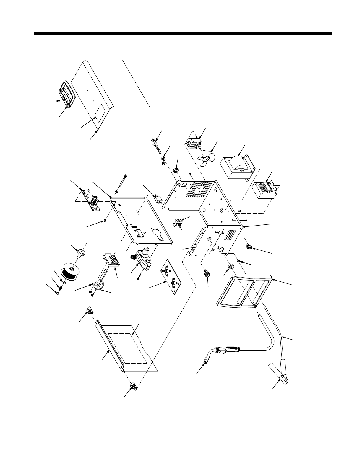
SECTION 9 − PARTS LIST
. Hardware is common and
not available unless listed.
29
28
30
15
27
21
16
22
17
18
19
1
20
24
23
5
33
3
7
10
2
8
26
11
12
25
14
13
36
37
9
OM-923 Page 36
6
4
32
35
31
34
6
804 124-B
Figure 8-1. Main Assembly
Page 41

Item
No.
Dia.
Mkgs.
Part
No.
Description
Figure 8-1. Main Assembly
1 210 432 CASE SECTION, front/bottom/rear 1. . . . . . . . . . . . . . . . . . . . . . . . . . . . . . . . . . . . . . . . . . . . . . . . . . . .
210 530 BLANK, snap-in 1. . . . . . . . . . . . . . . . . . . . . . . . . . . . . . . . . . . . . . . . . . . . . . . . . . . . . . . . . . . . . . . . . . . . . . . .
2 210 433 BAFFLE, center 1. . . . . . . . . . . . . . . . . . . . . . . . . . . . . . . . . . . . . . . . . . . . . . . . . . . . . . . . . . . . . . . . . . . .
3 +210 434 WRAPPER, cover 1. . . . . . . . . . . . . . . . . . . . . . . . . . . . . . . . . . . . . . . . . . . . . . . . . . . . . . . . . . . . . . . . . .
4 210 435 DOOR, access 1. . . . . . . . . . . . . . . . . . . . . . . . . . . . . . . . . . . . . . . . . . . . . . . . . . . . . . . . . . . . . . . . . . . . .
5 213 643 BEZEL, front 1. . . . . . . . . . . . . . . . . . . . . . . . . . . . . . . . . . . . . . . . . . . . . . . . . . . . . . . . . . . . . . . . . . . . . . .
6 196 006 HINGE, door access 2. . . . . . . . . . . . . . . . . . . . . . . . . . . . . . . . . . . . . . . . . . . . . . . . . . . . . . . . . . . . . . . . .
7 222 457 CIRCUIT CARD ASSY, control 1. . . . . . . . . . . . . . . . . . . . . . . . . . . . . . . . . . . . . . . . . . . . . . . . . . . . . . . .
8 134 201 STANDOFF 6. . . . . . . . . . . . . . . . . . . . . . . . . . . . . . . . . . . . . . . . . . . . . . . . . . . . . . . . . . . . . . . . . . . . . . . .
9 209 356 RECTIFIER, assy 1. . . . . . . . . . . . . . . . . . . . . . . . . . . . . . . . . . . . . . . . . . . . . . . . . . . . . . . . . . . . . . . . . . .
10 209 392 BUS BAR, output positive 1. . . . . . . . . . . . . . . . . . . . . . . . . . . . . . . . . . . . . . . . . . . . . . . . . . . . . . . . . . . .
11 193 194 BUS BAR, output negative 1. . . . . . . . . . . . . . . . . . . . . . . . . . . . . . . . . . . . . . . . . . . . . . . . . . . . . . . . . . .
12 210 109 SUPPLEMENTARY PROTECTOR, man reset 1P 25A 250VAC 1. . . . . . . . . . . . . . . . . . . . . . . . . . .
13 111 443 BUSHING, strain relief 1. . . . . . . . . . . . . . . . . . . . . . . . . . . . . . . . . . . . . . . . . . . . . . . . . . . . . . . . . . . . . . .
14 147 545 CORD SET 1. . . . . . . . . . . . . . . . . . . . . . . . . . . . . . . . . . . . . . . . . . . . . . . . . . . . . . . . . . . . . . . . . . . . . . . .
15 208 015 HANDLE 1. . . . . . . . . . . . . . . . . . . . . . . . . . . . . . . . . . . . . . . . . . . . . . . . . . . . . . . . . . . . . . . . . . . . . . . . . . .
16 209 467 MOTOR, fan 115VAC 1. . . . . . . . . . . . . . . . . . . . . . . . . . . . . . . . . . . . . . . . . . . . . . . . . . . . . . . . . . . . . . . .
17 210 413 BLADE, fan 1. . . . . . . . . . . . . . . . . . . . . . . . . . . . . . . . . . . . . . . . . . . . . . . . . . . . . . . . . . . . . . . . . . . . . . . .
18 209 213 TRANSFORMER 1. . . . . . . . . . . . . . . . . . . . . . . . . . . . . . . . . . . . . . . . . . . . . . . . . . . . . . . . . . . . . . . . . . .
19 203 868 STABILIZER 1. . . . . . . . . . . . . . . . . . . . . . . . . . . . . . . . . . . . . . . . . . . . . . . . . . . . . . . . . . . . . . . . . . . . . . .
20 196 575 SWITCH, rocker spst 1. . . . . . . . . . . . . . . . . . . . . . . . . . . . . . . . . . . . . . . . . . . . . . . . . . . . . . . . . . . . . . . .
21 229 432 SWITCH, rotary 1. . . . . . . . . . . . . . . . . . . . . . . . . . . . . . . . . . . . . . . . . . . . . . . . . . . . . . . . . . . . . . . . . . . . .
22 207 079 KNOB, pointer 1. . . . . . . . . . . . . . . . . . . . . . . . . . . . . . . . . . . . . . . . . . . . . . . . . . . . . . . . . . . . . . . . . . . . . .
23 210 398 BUSHING, snap-in 1. . . . . . . . . . . . . . . . . . . . . . . . . . . . . . . . . . . . . . . . . . . . . . . . . . . . . . . . . . . . . . . . . .
24 209 412 BUSHING, snap-in .500 dia 2. . . . . . . . . . . . . . . . . . . . . . . . . . . . . . . . . . . . . . . . . . . . . . . . . . . . . . . . . .
25 209 532 DRIVE, assy wire 1. . . . . . . . . . . . . . . . . . . . . . . . . . . . . . . . . . . . . . . . . . . . . . . . . . . . . . . . . . . . . . . . . . .
26 193 144 INSULATOR, output stud 1. . . . . . . . . . . . . . . . . . . . . . . . . . . . . . . . . . . . . . . . . . . . . . . . . . . . . . . . . . . .
27 202 726 ADAPTER, spool hub 1. . . . . . . . . . . . . . . . . . . . . . . . . . . . . . . . . . . . . . . . . . . . . . . . . . . . . . . . . . . . . . . .
28 202 998 SPRING, cprsn 1. . . . . . . . . . . . . . . . . . . . . . . . . . . . . . . . . . . . . . . . . . . . . . . . . . . . . . . . . . . . . . . . . . . . .
29 204 608 NUT 1. . . . . . . . . . . . . . . . . . . . . . . . . . . . . . . . . . . . . . . . . . . . . . . . . . . . . . . . . . . . . . . . . . . . . . . . . . . . . . .
30 203 072 WASHER 1. . . . . . . . . . . . . . . . . . . . . . . . . . . . . . . . . . . . . . . . . . . . . . . . . . . . . . . . . . . . . . . . . . . . . . . . . .
31 225 397 H-9B GUN, 8 ft .023-.035 1. . . . . . . . . . . . . . . . . . . . . . . . . . . . . . . . . . . . . . . . . . . . . . . . . . . . . . . . . . . .
32 223 790 LABEL, setup guide 1. . . . . . . . . . . . . . . . . . . . . . . . . . . . . . . . . . . . . . . . . . . . . . . . . . . . . . . . . . . . . . . . .
33 204 036 LABEL, warning 1. . . . . . . . . . . . . . . . . . . . . . . . . . . . . . . . . . . . . . . . . . . . . . . . . . . . . . . . . . . . . . . . . . . .
34 208 820 CLAMP, work 1. . . . . . . . . . . . . . . . . . . . . . . . . . . . . . . . . . . . . . . . . . . . . . . . . . . . . . . . . . . . . . . . . . . . . . .
35 196 619 CABLE, work 1. . . . . . . . . . . . . . . . . . . . . . . . . . . . . . . . . . . . . . . . . . . . . . . . . . . . . . . . . . . . . . . . . . . . . . .
36 210 530 BLANK, snap−in nyl 1.250 mtg hole black 1. . . . . . . . . . . . . . . . . . . . . . . . . . . . . . . . . . . . . . . . . . . . . .
37 LABEL, nameplate (order by model and serial no.) 1. . . . . . . . . . . . . . . . . . . . . . . . . . . . . . . . . . . . . . . . . . . . . . .
Quantity
+When ordering a component originally displaying a precautionary label, the label should also be ordered.
To maintain the factory original performance of your equipment, use only Manufacturer’s Suggested
Replacement Parts. Model and serial number required when ordering parts from your local distributor.
OM-923 Page 37
Page 42
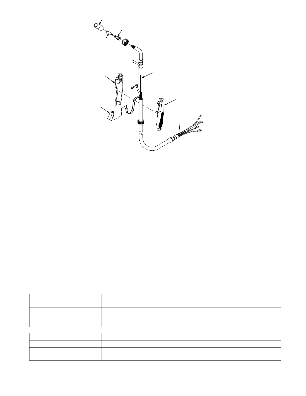
5 − See Table 8-1
1
2
7
3
4
7
6
Figure 8-2. H-9B Gun
Item
No.
Part
No.
225 397
Description
Figure 8-2. H-9B Gun
1 169 715 NOZZLE, slip type .500 orf flush 1. . . . . . . . . . . . . . . . . . . . . . . . . . . . . . . . . . . . . . . . . . . . . . . . . . . .
1 ♦226 190 NOZZLE, flux cored slip type 1. . . . . . . . . . . . . . . . . . . . . . . . . . . . . . . . . . . . . . . . . . . . . . . . . . . . . .
2 169 716 ADAPTER, contact tip 1. . . . . . . . . . . . . . . . . . . . . . . . . . . . . . . . . . . . . . . . . . . . . . . . . . . . . . . . . . . . .
3 225 410 SWITCH, trigger 1. . . . . . . . . . . . . . . . . . . . . . . . . . . . . . . . . . . . . . . . . . . . . . . . . . . . . . . . . . . . . . . . . .
4 210 970 LINER, monocoil .023/.035 wire x 8ft 1. . . . . . . . . . . . . . . . . . . . . . . . . . . . . . . . . . . . . . . . . . . . . . . . .
5 ♦087 299 TIP, contact scr .023 wire x 1.125. . . . . . . . . . . . . . . . .
5 000 067 TIP, contact scr .030 wire x 1.125 1. . . . . . . . . . . . . . . . . . . . . . . . . . . . . . . . . . . . . . . . . . . . . . . . . . . .
5 ♦000 068 TIP, contact scr .035 wire x 1.125. . . . . . . . . . . . . . . . .
6 226 010 NUT, liner retainer 1. . . . . . . . . . . . . . . . . . . . . . . . . . . . . . . . . . . . . . . . . . . . . . . . . . . . . . . . . . . . . . . . .
7 226 080 HANDLE ASSY 1. . . . . . . . . . . . . . . . . . . . . . . . . . . . . . . . . . . . . . . . . . . . . . . . . . . . . . . . . . . . . . . . . . .
804 243-A
Quantity
♦OPTIONAL
To maintain the factory original performance of your equipment, use only Manufacturer’s Suggested
Replacement Parts. Model and serial number required when ordering parts from your local distributor.
Table 8-1. Contact Tip Options
HOBART PART NO. DESCRIPTION REMARKS
196 131 Tip, contact scr .030 wire Pkg of 5
196 132 Tip, contact scr .035 wire Pkg of 5
196 137 Nozzle, slip type .500 orf flush Qty 1
196 135 Adapter, contact tip Qty 1
WELD-IT PART NO. DESCRIPTION REMARKS
770 174 Tip, contact scr .023 wire Pkg of 5
770 177 Tip, contact scr .030 wire Pkg of 5
770 180 Tip, contact scr .035 wire Pkg of 5
OM-923 Page 38
Page 43
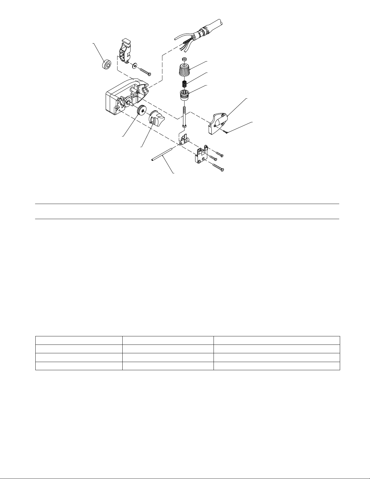
1
6
7
8
5
9
2
3
4
803 442-B
Figure 8-3. Wire Drive Assembly
Item
No.
Part
No.
209 532
QuantityDescription
Figure 8-3. Wire Drive Assembly
1 212 377 BEARING, idler 1. . . . . . . . . . . . . . . . . . . . . . . . . . . . . . . . . . . . . . . . . . . . . . . . . . . . . . . . . . . . . . . . . . . .
2 212 379 ROLL, drive .024-.030/.035 1. . . . . . . . . . . . . . . . . . . . . . . . . . . . . . . . . . . . . . . . . . . . . . . . . . . . . . . . . .
3 212 383 RETAINER, feedroll 1. . . . . . . . . . . . . . . . . . . . . . . . . . . . . . . . . . . . . . . . . . . . . . . . . . . . . . . . . . . . . . . .
4 212 368 GUIDE, wire inlet 1. . . . . . . . . . . . . . . . . . . . . . . . . . . . . . . . . . . . . . . . . . . . . . . . . . . . . . . . . . . . . . . . . . .
5 212 384 COVER, torch 1. . . . . . . . . . . . . . . . . . . . . . . . . . . . . . . . . . . . . . . . . . . . . . . . . . . . . . . . . . . . . . . . . . . . .
6 212 385 KNOB, tension 1. . . . . . . . . . . . . . . . . . . . . . . . . . . . . . . . . . . . . . . . . . . . . . . . . . . . . . . . . . . . . . . . . . . . .
7 212 387 SPRING, compression 1. . . . . . . . . . . . . . . . . . . . . . . . . . . . . . . . . . . . . . . . . . . . . . . . . . . . . . . . . . . . . .
8 212 388 CUP, spring 1. . . . . . . . . . . . . . . . . . . . . . . . . . . . . . . . . . . . . . . . . . . . . . . . . . . . . . . . . . . . . . . . . . . . . . . .
9 212 389 SCREW, torch cover 1. . . . . . . . . . . . . . . . . . . . . . . . . . . . . . . . . . . . . . . . . . . . . . . . . . . . . . . . . . . . . . . .
To maintain the factory original performance of your equipment, use only Manufacturer’s Suggested
Replacement Parts. Model and serial number required when ordering parts from your local distributor.
Table 8-2. Options
PART NO. DESCRIPTION REMARKS
194 776 Small Running Gear/Cylinder Rack To Mount Unit For Maneuverability
195 216 Hub Kit For 8 in Wire Spool
195 186 Protective Cover Weatherproof Nylon
NOTE: If individual parts are required, see Parts List chapter of this manual for part number to order.
OM-923 Page 39
Page 44

Notes
Page 45

Notes
Page 46

Notes
Page 47

Warranty Questions?
Call
1-800-332-3281
7 AM − 6 PM EST
Service
You always get the fast,
reliable response you
need. Most replacement
parts can be in your
hands in 24 hours.
Support
Need fast answers to the
tough welding questions?
Contact your distributor or
call 1-800-332-3281. The
expertise of the distributor
and Hobart is there to
help you, every step of
the way.
Assistance
Visit the Hobart website:
www.HobartWelders.com
Effective January 1, 2008
5/3/1 WARRANTY applies to all Hobart welding equipment, plasma cutters and spot welders with a
serial number preface of LJ or newer.
This limited warranty supersedes all previous Hobart warranties and is exclusive with
Hobart products are serviced by Hobart or Miller Authorized Service Agencies.
LIMITED WARRANTY − Subject to the terms and conditions
below, Hobart/Miller Electric Mfg. Co., Appleton, Wisconsin,
warrants to its original retail purchaser that new Hobart
equipment sold after the effective date of this limited warranty is
free of defects in material and workmanship at the time it is
shipped by Hobart. THIS WARRANTY IS EXPRESSLY IN LIEU
OF ALL OTHER WARRANTIES, EXPRESS OR IMPLIED,
INCLUDING THE WARRANTIES OF MERCHANTABILITY AND
FITNESS.
Within the warranty periods listed below, Hobart/Miller will repair
or replace any warranted parts or components that fail due to
such defects in material or workmanship. Hobart/Miller must be
notified in writing within thirty (30) days of such defect or failure, at
which time Hobart/Miller will provide instructions on the warranty
claim procedures to be followed.
Hobart/Miller shall honor warranty claims on warranted
equipment listed below in the event of such a failure within the
warranty time periods. All warranty time periods start on the
delivery date of the equipment to the original retail purchaser, and
not to exceed one year after the equipment is shipped to a North
American distributor or eighteen months after the equipment is
shipped to an International distributor.
1. 5 Years — Parts and Labor
* Original Main Power Rectifiers only to include SCRs,
diodes, and discrete rectifier modules
* Transformers
* Stabilizers
* Reactors
2. 3 Years — Parts and Labor
* Drive Systems
* PC Boards
* Rotors, Stators and Brushes
* Idle Module
* Solenoid Valves
* Switches and Controls
* Spot Welder Transformer
3. 1 Year — Parts and Labor Unless Specified
(90 days for industrial use)
* Motor-Driven Guns
* MIG Guns/TIG Torches
* Relays
* Contactors
* Regulators
* Water Coolant Systems
* Flowgauge and Flowmeter Regulators (No Labor)
* HF Units
* Running Gear/Trailers
* Plasma Cutting Torches
* Remote Controls
* Replacement Parts (No labor) − 90 days
* Accessories
* Field Options
(NOTE: Field options are covered for the remaining
warranty period of the product they are installed in, or
for a minimum of one year — whichever is greater.)
4. Engines, batteries and tires are warranted separately by
the manufacturer.
no other guarantees or warranties expressed or implied.
Hobart’s 5/3/1 Limited Warranty shall not apply to:
1. Consumable components such as contact tips,
cutting nozzles, slip rings, drive rolls, gas diffusers,
plasma torch tips and electrodes, weld cables, and
tongs and tips, or parts that fail due to normal wear.
(Exception: brushes, slip rings, and relays are covered
on Hobart Engine-Driven models.)
2. Items furnished by Hobart/Miller, but manufactured by
others, such as engines or trade accessories. These
items are covered by the manufacturer’s warranty, if
any.
3. Equipment that has been modified by any party other
than Hobart/Miller, or equipment that has been
improperly installed, improperly operated or misused
based upon industry standards, or equipment which has
not had reasonable and necessary maintenance, or
equipment which has been used for operation outside of
the specifications for the equipment.
HOBART PRODUCTS ARE INTENDED FOR PURCHASE AND
USE BY COMMERCIAL/INDUSTRIAL USERS AND PERSONS
TRAINED AND EXPERIENCED IN THE USE AND
MAINTENANCE OF WELDING EQUIPMENT.
In the event of a warranty claim covered by this warranty, the
exclusive remedies shall be, at Hobart’s/Miller’s option: (1) repair;
or (2) replacement; or, where authorized in writing by
Hobart/Miller in appropriate cases, (3) the reasonable cost of
repair or replacement at an authorized Hobart/Miller service
station; or (4) payment of or credit for the purchase price (less
reasonable depreciation based upon actual use) upon return of
the goods at customer’s risk and expense. Hobart’s/Miller’s
option of repair or replacement will be F.O.B., Factory at
Appleton, Wisconsin, or F.O.B. at a Hobart/Miller authorized
service facility as determined by Hobart/Miller. Therefore no
compensation or reimbursement for transportation costs of any
kind will be allowed.
TO THE EXTENT PERMITTED BY LAW, THE REMEDIES
PROVIDED HEREIN ARE THE SOLE AND EXCLUSIVE
REMEDIES. IN NO EVENT SHALL HOBART/MILLER BE
LIABLE FOR DIRECT, INDIRECT, SPECIAL, INCIDENTAL OR
CONSEQUENTIAL DAMAGES (INCLUDING LOSS OF
PROFIT), WHETHER BASED ON CONTRACT, TORT OR ANY
OTHER LEGAL THEORY.
ANY EXPRESS WARRANTY NOT PROVIDED HEREIN AND
ANY IMPLIED WARRANTY, GUARANTY OR
REPRESENTATION AS TO PERFORMANCE, AND ANY
REMEDY FOR BREACH OF CONTRACT TORT OR ANY
OTHER LEGAL THEORY WHICH, BUT FOR THIS PROVISION,
MIGHT ARISE BY IMPLICATION, OPERATION OF LAW,
CUSTOM OF TRADE OR COURSE OF DEALING, INCLUDING
ANY IMPLIED WARRANTY OF MERCHANTABILITY OR
FITNESS FOR PARTICULAR PURPOSE, WITH RESPECT TO
ANY AND ALL EQUIPMENT FURNISHED BY
HOBART/MILLER IS EXCLUDED AND DISCLAIMED BY
Hobart/Miller.
Some states in the U.S.A. do not allow limitations of how long an
implied warranty lasts, or the exclusion of incidental, indirect,
special or consequential damages, so the above limitation or
exclusion may not apply to you. This warranty provides specific
legal rights, and other rights may be available, but may vary from
state to state.
In Canada, legislation in some provinces provides for certain
additional warranties or remedies other than as stated herein,
and to the extent that they may not be waived, the limitations and
exclusions set out above may not apply. This Limited Warranty
provides specific legal rights, and other rights may be available,
but may vary from province to province.
hobart_warr 2008-01
Page 48
Owner’s Record
Please complete and retain with your personal records.
Model Name Serial/Style Number
Purchase Date (Date which equipment was delivered to original customer.)
Distributor
Address
Protect Your Investment!
City
State Zip
Resources Available
Always provide Model Name and Serial/Style Number.
To locate a Distributor,
retail or service location:
Call 1-877-Hobart1 or visit our website at
www.HobartWelders.com
Contact your Distributor for:
Welding Supplies and Consumables
Options and Accessories
Register your product at:
HobartWelders.com
Personal Safety Equipment
For technical assistance:
Call 1-800-332-3281
Contact the Delivering Carrier to:
PRINTED IN USA © 2008 Hobart Welding Products.2008−01
Service and Repair
Replacement Parts
Training (Schools, Videos, Books)
Technical Manuals (Servicing Information
and Parts)
Circuit Diagrams
Welding Process Handbooks
File a claim for loss or damage during
shipment.
For assistance in filing or settling claims, contact
your distributor and/or equipment manufacturer’s
Transportation Department.
Hobart Welding Products
An Illinois Tool Works Company
600 West Main Street
Troy, OH 45373 USA
For Technical Assistance:
Call1-800-332-3281
For Literature Or Nearest Dealer:
Call 1-877-Hobart1
 Loading...