

Hobart Service CUH, CUL Service Manual

SERVICE MANUAL
CENTERLINE DISHWASHER
CUH, High Temp ML-130363
CUL, Low Temp ML-130364
- NOTICE -
This Manual is prepared for the use of trained Hobart Service
Technicians and should not be used by those not properly
qualified.
This manual is not intended to be all encompassing. If you have
not attended a Hobart Service School for this product, you should
read, in its entirety, the repair procedure you wish to perform to
determine if you have the necessary tools, instruments and skills
required to perform the procedure. Procedures for which you do
not have the necessary tools, instruments and skills should be
performed by a trained Hobart Service Technician.
The reproduction, transfer, sale or other use of this manual,
without the express written consent of Hobart, is prohibited.
This manual has been provided to you by ITW Food Equipment
Group LLC ("ITW FEG") without charge and remains the property
of ITW FEG, and by accepting this manual you agree that you will
return it to ITW FEG promptly upon its request for such return at
any time in the future.
A product of Hobart Service 701 S. Ridge Ave Troy, OH 45374
F45743 (0419)

CENTERLINE DISHWASHER
TABLE OF CONTENTS
GENERAL .................................................................................................. 3
INTRODUCTION ....................................................................................... 3
SPECIFICATIONS ...................................................................................... 3
TOOLS ................................................................................................. 4
WALL CHART .......................................................................................... 4
PROGRAMMING CARD ................................................................................ 4
OPERATION ERROR CARD ............................................................................ 5
PROGRAMMING ........................................................................................... 6
PROGRAMMING MENU ................................................................................ 6
CONFIGURATION MENU .............................................................................. 6
ELECTRICAL OPERATION ................................................................................. 8
COMPONENT LOCATION & DESCRIPTION ............................................................ 8
WIRING DIAGRAM ..................................................................................... 9
CONTROL BOARD - WIRE CONNECTIONS ........................................................... 10
SERVICE ADJUSTMENTS AND PROCEDURES ........................................................... 12
HYDRAULIC DIAGRAM (CUH ONLY) .................................................................. 12
WATER FLOW DIAGRAM
............................................................................. 13
REMOVAL AND REPLACEMENT ......................................................................... 14
SERVICE POSITION .................................................................................. 14
BOTTOM PANEL ...................................................................................... 15
FRONT PANEL ....................................................................................... 17
DOOR CATCH ........................................................................................ 18
DOOR SEAL & GASKET .............................................................................. 19
DOOR ................................................................................................ 20
CHEMICAL PUMP MOTORS .......................................................................... 22
WASH PUMP MOTOR ................................................................................ 24
RINSE PUMP MOTOR ................................................................................ 26
TRANSFORMER ...................................................................................... 27
BOOSTER ............................................................................................ 27
TROUBLESHOOTING ..................................................................................... 28
ERROR CODES ...................................................................................... 28
TROUBLESHOOTING DISHWARE .................................................................... 30
© HOBART SERVICE 2019
F45743 (0419) Page 2 of 31
CENTERLINE DISHWASHER - GENERAL
GENERAL
INTRODUCTION
Specified unit is NSF rated, ENERGY STAR® certified Centerline by Hobart high temperature undercounter
dishwasher. Features soft start, two selectable cycles, one standard 2-minute cycle with optional extended cycle
(factory set at 240 seconds); .84 gallons per rack, LED temperature and operator display, service diagnostics,
detergent and rinse aid pumps. Constructed of stainless steel.
MODELS
Model DESCRIPTION
CUH High temperature rinse.
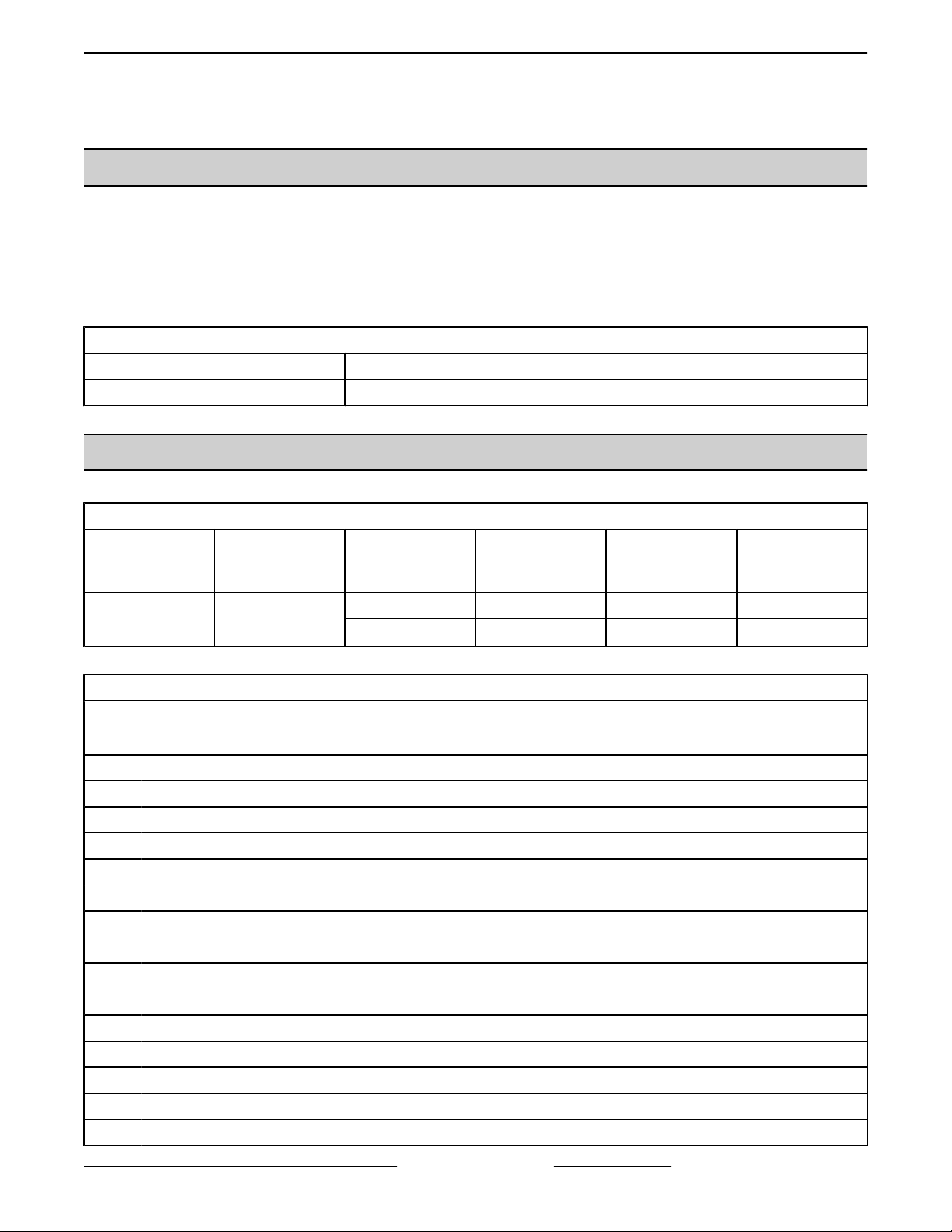
SPECIFICATIONS
STANDARD ELECTRICAL OPTIONS
MODEL HEAT TYPE ELEC SPECS RATED AMPS
CUH
Electric
High Temp Rinse
208/60/1 24.2 30 30
240/60/1 27.5 30 30
MIN SUPPLY
CIRCUIT
AMPACITY
MAXIMUM
PROTECTIVE
DEVICE
Capacities
Cycle Time (seconds) 120
Racks per Hour 24
Tank Capacity - US Gallons 5.3
Motor Horsepower
Wash 0.62
Rinse 0.20
Water Consumption
U.S. Gallons per Hour (maximum use) 20.2
U.S. Gallons per Rack (maximum use) 0.84
Peak Drain Flow - U.S. Gallons 2.8
Temperatures °F
Wash 150°F
Rinse 180°F
Incoming Water Temperature (minimum recommenced) 110°F
SPECIFICATIONS
CUH
High Temp Rinse
Page 3 of 31 F45743 (0419)

CENTERLINE DISHWASHER - GENERAL
SPECIFICATIONS
Heating
Tank Heat, electric (kW) 5.5
Electric Booster (kW) 6.0
Standard 20" x 20" (508 x 508) Rack Complement
Flat 1
Peg 1
Machine Timing
Wash Minimum 90 Sec.
Rinse Minimum 15 Sec.
Standard Tools
Standard set of hand tools.
•
CUH
High Temp Rinse
TOOLS
• Metric set of hand tools.
• VOM with measuring micro amp current tester. Any VOM with minimum of CAT III 600V, CE certified. Sensitivity
of at least 20,000 ohms per volt can be used. In addition, meter leads must also be a minimum of CAT III 600V.
• Clamp on type amp meter with minimum of NFPA-70E CAT III 600V, UL/CSA/TUV listed.
• Temperature tester (thermocouple type).
• Field service grounding kit.
Special Tools
• EW-199069 – Door Shim.
• EW-199070 – Door Side Shim.
• EW-199061 – Drain Body.
• EW-199067 – Lower Manifold Nut.
• EW-199068 – Upper Manifold Nut.
WALL CHART
Centerline Wall Chart
PROGRAMMING CARD
Programming Card
F45743 (0419) Page 4 of 31

Operation Error Card
CENTERLINE DISHWASHER - GENERAL
OPERATION ERROR CARD
Page 5 of 31 F45743 (0419)
CENTERLINE DISHWASHER - PROGRAMMING
PROGRAMMING
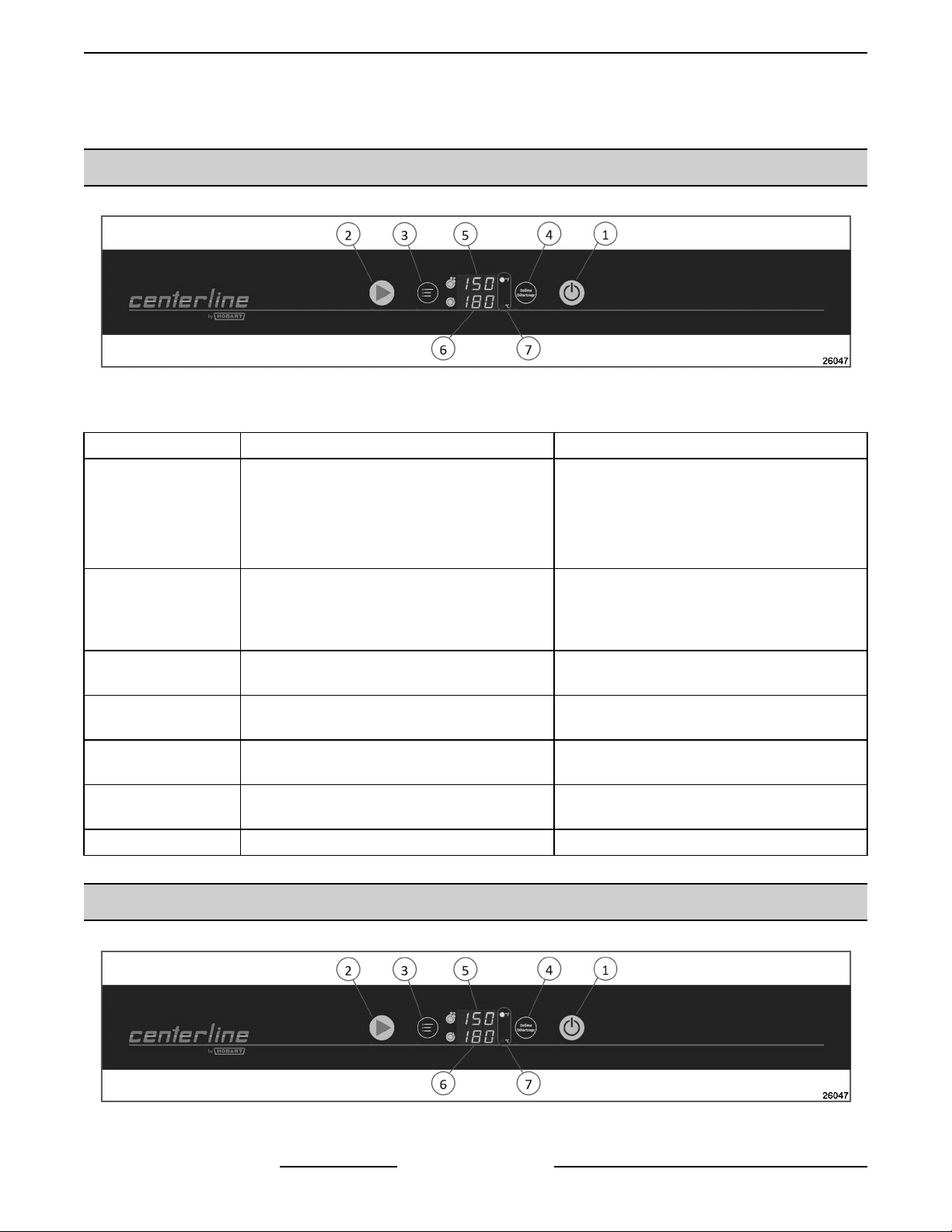
PROGRAMMING MENU
Fig. 1
ITEM NAME DESCRIPTION
Pressing this button switches the machine
on, fills and heats the wash tank.
1 Power / Drain Button
2 Start Button
3 Menu Button
4 Delime Button
5 Temperature Display, Wash Tank
6 Temperature Display, Rinse
7 Temperature Units LED lights for °F or °C.
Pressing and holding (3 seconds) activates
self-cleaning
switches the machine off automatically.
Pressing this button starts the wash cycle. If
pressed a 2nd time within 10 seconds of the
first press, the extended wash cycle is
activated.
Pressing this button enters the configuration
menu.
Pressing and holding this button (3 seconds)
initiates the deliming cycle.
Displays wash tank temperature while
machine is in ready state or in a wash cycle.
Displays rinse temperature only when rinse is
active.
cycle, drains machine, and then
CONFIGURATION MENU
Fig. 2
F45743 (0419) Page 6 of 31

CENTERLINE DISHWASHER - PROGRAMMING
ITEM NAME ITEM NAME
1 Power / Drain Button 5 Temperature Display, Wash Tank
2 Start Button 6 Temperature Display, Rinse
3 Menu Button 7 Temperature Units
4 Delime Button
1. Push and hold Power button to turn off machine.
2. While
3. With machine off and door open, press and hold "Menu" and "Delime" button simultaneously until display
4. Close door.
5. Press "Start" button until display reads 23 parameter.
6. Press "Delime" button to select 23 parameter.
7. Press "Power" button for 3 seconds, to select dishwasher parameter.
8. Press and hold "Power" button for 5 seconds to set parameter. LED light under Power button will flash indicating
9. Open door to exit program.
machine is draining, push and hold Power button within 20 seconds, until machine powers off and drain
stops.
changes.
NOTE: Verify LED lights, located underneath the buttons, are lit up.
• 01 = Cold Unit Program (CUL)
• 02 = Hot Unit Program (CUH)
selection is complete.
Page 7 of 31 F45743 (0419)
CENTERLINE DISHWASHER - ELECTRICAL OPERATION
ELECTRICAL OPERATION
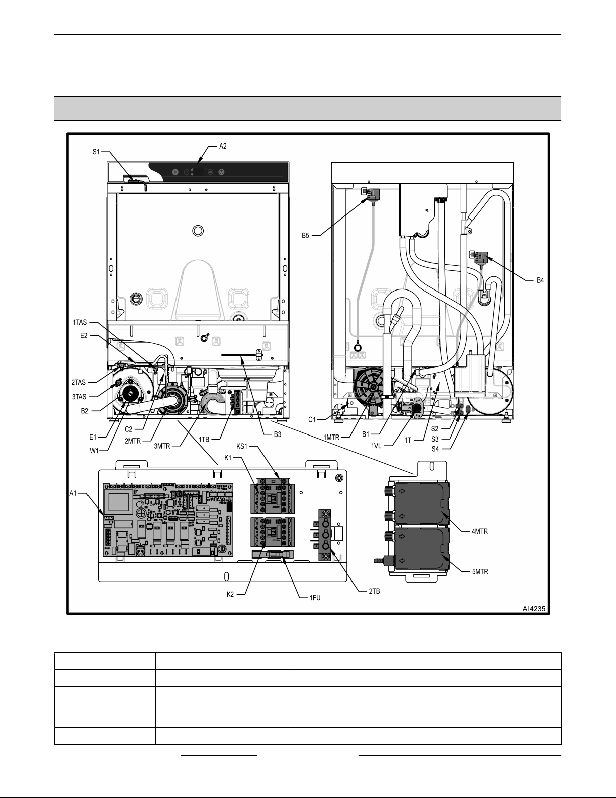
COMPONENT LOCATION & DESCRIPTION
Fig. 3
CALLOUT COMPONENT NAME DEFINITION
A1 Control Board Controls operation of dishwasher.
Provides user interface to control board. Visual display
A2 User Interface
B1 Rinse Probe Measures final rinse tank temperature.
F45743 (0419) Page 8 of 31
shown in window of keypad. Shows machine operation and
programming.
CENTERLINE DISHWASHER - ELECTRICAL OPERATION
CALLOUT COMPONENT NAME DEFINITION
B2 Booster Temp Probe Measures booster tank temperature.
B3 Tank Temp Probe Measures wash tank temperature.
B4 Booster Pressure Sensor
B5 Tank Pressure Sensor
C1 Wash Pump Capacitor
C2 Rinse Pump Capacitor
E1 Booster Heater Heats water in booster.
E2 Tank Heating Element Heats water in tank.
1FU Control Fuse Protects control board and overload from power surges.
K1 Booster Contactor Controls power to booster heater.
K2 Tank Contactor Controls power to tank heater.
KS1 Control Contactor Switch Controls power to tank heater thermostats (1TAS & 2TAS).
1MTR Wash Pump Motor Drives wash pump, which pumps for wash cycles.
2MTR Rinse Pump Motor Drives rinse pump, which pumps for rinse cycles.
3MTR Drain Pump Motor Drives drain pump, which pumps drain cycles.
4MTR Det. Pump
5MTR Rinse Aid Pump Drives rinse aid pump, which pumps rinse aid into machine.
S1 Door Switch Disables wash and rinse pumps while door is open.
S2 Det. Level Sensor Detects presence of detergent in tube.
S3 Rinse Aid Level Sensor Detects presence of rinse aid in tube.
S4 Sanitizer Level Sensor Detects presence of sanitizer in tube
1T Transformer
1TAS Tank Thermostat Tank temp sensor.
2TAS Tank Thermostat Tank temp sensor.
3TAS Booster Thermostat Booster temp sensor.
1TB Terminal Block Connects incoming line voltage to controls.
2TB Terminal Block Connects group neutral.
1VL Fill Valve
W1
Booster Heating Element
Bridge
Supplies mV reading for water level in booster. Acceptable
range: 0.5 - 0.78 mV.
Supplies mV reading for water level in tank. Acceptable
range: 0.5 - 0.73 mV.
Drives detergent pump, which pumps detergent into
machine.
Transforms primary voltage down to secondary voltage
(120VAC).
When energized, allows water to enter the holding tank or
booster.
Jumpers booster elements.
Centerline Wiring Diagram
WIRING DIAGRAM
Page 9 of 31 F45743 (0419)
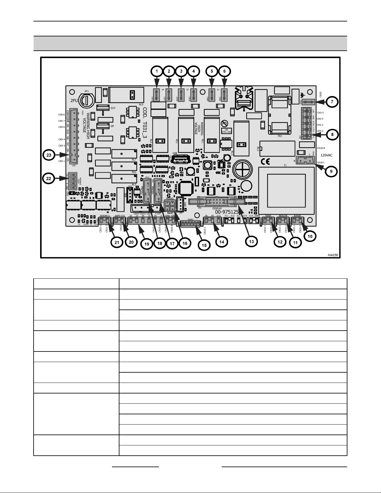
CENTERLINE DISHWASHER - ELECTRICAL OPERATION
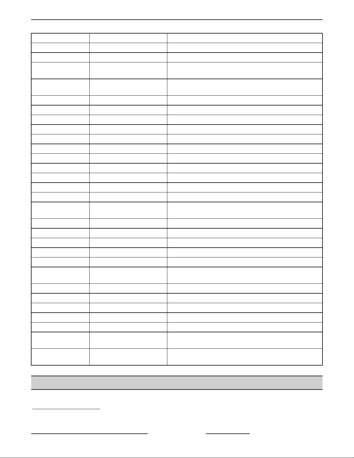
CONTROL BOARD - WIRE CONNECTIONS
Fig. 4
CALLOUT DESCRIPTION
1 To rinse pump motor.
2
3 To tank overtemp (1TAS).
4
5 To booster overtemp (3TAS).
6
7 CN20 connects to ground.
8
9
From main power through fuse (1FU).
CN7C connects to CN5-5.
CN7A connects to CN9-8 (COM).
CN7A connects to CN6A.
CN6A connects to CN7A.
CN6A connects to CN18L.
CN5-2 connects to wash pump motor (1MTR).
CN5-3 connects to wash pump motor (1MTR).
CN5-4 connects to 2TB-L.
CN5-5 connects to CN7C.
CN18-L connects to CN6A.
CN18-N connects to 2TB-N.
F45743 (0419) Page 10 of 31
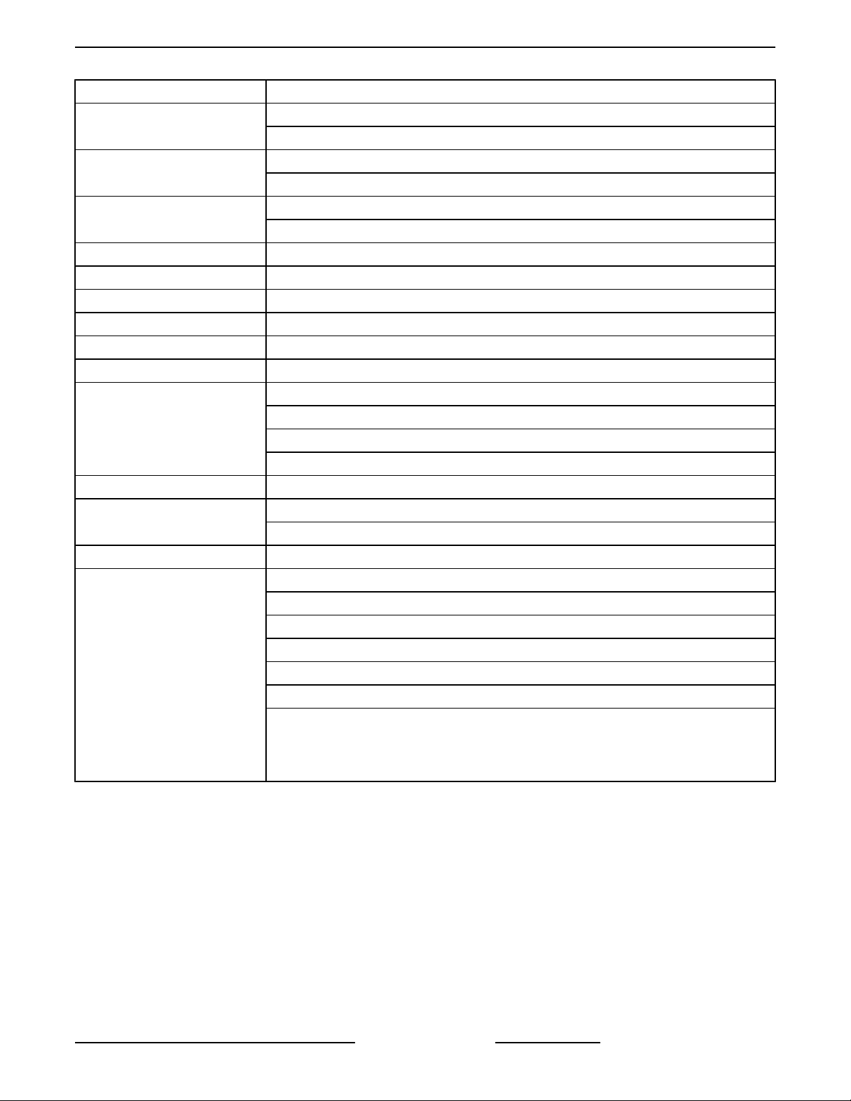
CENTERLINE DISHWASHER - ELECTRICAL OPERATION
CALLOUT DESCRIPTION
10
11
12
13 Connects to display / user interface.
14 CN16-1 connects to sanitizer level sensor connector S4.
15 Not used.
16 CN22 - designated jumper.
17 PRESS1 to booster pressure sensor.
18 PRESS2 to tank pressure sensor.
19
20 CN10 jumpered.
21
22 MODBUS communications.
23
CN23-1 connects to rinse probe.
CN23-2 connects to rinse probe.
CN13-1 connects to booster temp probe CN13.
CN13-2 connects to booster temp probe CN13.
CN14-1 connects to tank temp probe CN14.
CN14-2 connects to tank temp probe CN14.
CN15-5 connects to rinse aid level sensor connector S3.
CN15-6 connects to detergent level sensor connector S2.
CN15-7 connects to detergent level sensor connector S2.
CN15-8 connects to rinse aid level sensor connector S3.
CN21-1 connects to door switch CN21.
CN21-2 connects to door switch CN21.
CN9-1 connects to fill valve.
CN9-3 connects to detergent pump motor.
CN9-4 connects to rinse aid pump motor.
CN9-6 connects to drain pump.
CN9-7 connects to transformer (1T-X1).
CN9-8 connects to CN7A.
NOTE:
board. 120VAC power from transformer X1 comes into board on CN9-7, goes
through PF1 fuse (2FU), comes back out on CN9-8 and then runs to tank heat board
relay, booster heat board relay, and then board power (CN18).
CN9-7 (COMF) and CN9-8 (COM) are connected to fuse 2FU (PF1) on the
Page 11 of 31 F45743 (0419)
 Loading...