

Hobart Food Machines WS-P213 Installation Manual

INSTALLATION & PARTS
INSTRUCTIONS
HOBART
WATER SOFTENING
SYSTEM
WS-P213
- NOTICE This Manual is prepared for the use of trained Hobart Service
Technicians and should not be used by those not properly qualified.
If you have attended a Hobart Service School for this product, you
may be qualified to perform all the procedures described in this
manual.
This manual is not intended to be all encompassing. If you have not
attended a Hobart Service School for this product, you should read,
in its entirety, the repair procedure you wish to perform to
determine if you have the necessary tools, instruments and skills
required to perform the procedure. Procedures for which you do not
have the necessary tools, instruments and skills should be
performed by a trained Hobart Service Technician.
Reproduction or other use of this Manual, without the express
written consent of Hobart, is prohibited.
A product of HOBART TROY, OHIO 45374
F25312 (January 2009)

TABLE OF CONTENTS
INSTALLATION ............................................................................ 2
DISC SELECTION .......................................................................... 7
REPLACEMENT PARTS ..................................................................... 8
© HOBART 2009
INSTALLATION
SAVE THESE INSTRUCTIONS
1. Determine location to install equipment. Make
sure the unit will be on a flat surface.
2. If sand, silt, or turbidity is present, install a
separate prefilter.
3. Install by-pass valving. Be certain to note the
inlet and outlet arrows on the valve head.
4. Connect the inlet/outlet adapters leading to the
softener using the proper size plumbing.
5. Plumb as necessary to accommodate the bypas valve and to complete the installation.
NOTE: Actual installation of by-pass valving may
vary from installation to installation. Be sure to follow
state and local codes.
NOTE: When installing a plastic component in line, it
is recommended that grounding straps be put in
place before the lines are actually cut to ensure the
ground is never broken.
NOTE: Do not solder brass adapters while inserted
in the module base. Damage to plastic and rubber
parts may result due to the heat. In addition, the
materials used in the soldering process may attack
certain types of plastics.
F25312 (January 2009) Page 2 of 12
NOTE: Care should be taken during the installation
process to assure that solder and flux do not come in
contact with the media tanks, the control module,
and related components.
6. After all plumbing is completed, but before
connecting equipment, flush both the inlet and
outlet lines by opening the by-pass valve and
allowing water to rinse out any debris in the
lines.
7. Locate enclosed kit containing four O-rings, two
pipes with O-rings, and the silicone packet.
Apply a liberal amount of silicone to the four Orings, and the O-rings in the two pipes. Install
the four O-rings on the inlet/outlet adapters.
8. Connect the main tank with softener valve to the
inlet/outlet adapter. The inlet/outlet adapter is
inserted into the control valve and locked in
place by the plastic E-clips.
NOTE: Be certain the E-clips are fully inserted into
the valve. Check to make sure that all three tabs on
the E-clips are fully inserted.
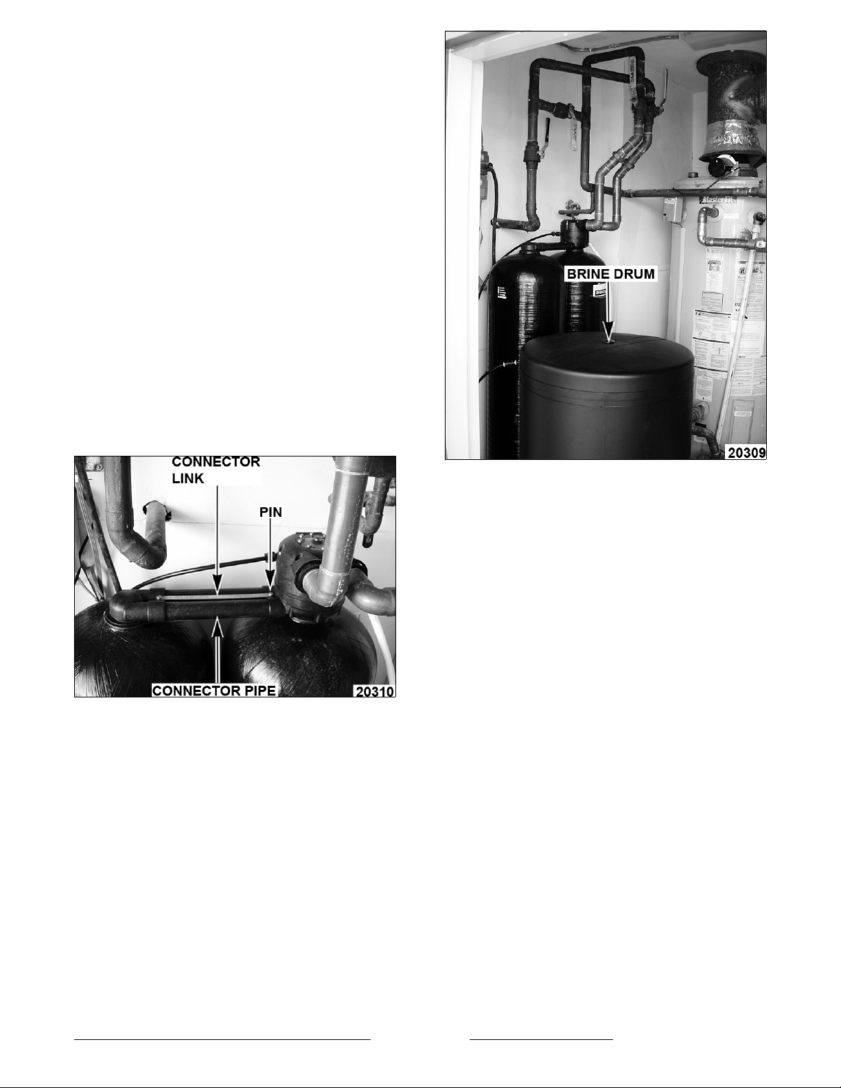
9. Connect the remote tank to the main tank using
connector pipes, connector links and connector
pins.
NOTE: Always use both links and pins.
10. Run a drain line to the discharge point.
NOTE: Follow state and local codes.
11. Before connecting unit, check for obstructions
or kinks. Apply Teflon tape to pipe threads on
side of softener valve, and install the two fittings
supplied. Connect drain line to valve.
NOTE: An air gap must be provided for all drain
lines. Check state and local plumbing codes for
proper setup of drain line air gaps.
NOTE: In Hobart Softeners, the brine drum mixes
and stores a solution of salt or potassium chloride for
regeneration of the softener media. During the brine
rinse cycle, this solution is drawn from the brine
drum and through the media to regenerate it.
The brine drum contains an adjustment to draw the
correct amount of salt or potassium chloride solution
for each cycle. This adjustment is made in two
places, the adjuster tube and the float cup.
NOTE: The adjuster tube measures the amount of
solution that is drawn from the brine drum into the
softener during the brine rinse cycle. The float cup
height determines how much softened water flows
back into the brine drum to prepare for the next
regeneration.
The adjuster tube is set by cutting and removing tabs
on both sides of the tube. Cut across each tab
horizontally, following the channel in the plastic.
Break off each tab individually until the proper setting
is reached. The remaining number or letter imprinted
on the tab determines the correct setting.
NOTE: On drain lines that must travel more than 8
feet up and 30 feet over, it is best to take the 5/8"
drain line that fits the valve and attach it in a larger
diameter line or pipe.
12. Position the brine drum.
F25312 (January 2009)Page 3 of 12

NOTE: The float cup height determines how much
softened water flows back into the brine drum to
prepare for the next regeneration.
The float cup is set by adjusting its height above the
bottom of the Brine Valve Assembly. By removing
the brine valve assembly and resting it on a flat
surface, the height of the float cup can be measured
with a ruler.
The height is measured from the base of the brine
valve assembly to the top of the float cup.
NOTE: Standard settings are defined by markings on
the rod of the brine valve assembly. Where the
predefined settings are not adequate, the actual float
cup height must be measured and the setting must
be measured and set according to the measured
float cup height.
Determining the correct brine valve setting for a
particular application is a three step process:
1. Determine the compensated hardness. This
requires a hardness test and an iron test on raw
water at the application site. Compensated
hardness is calculated by multiplying the ferrous
iron (in ppm) by 3 and adding it to the grains of
hardness.
F25312 (January 2009) Page 4 of 12
 Loading...