

Page 1

SERVICE MA NUAL
HQC45 & 90 SERIES
QUICK CHILLERS
MODEL ML#
HQC45 ML # 124059
HQC45 ML # 124066
HQCF45 ML # 124060
HQCF45 ML # 124067
HQC90 ML # 124063
HQC90 ML # 124068
- NOTICE This Manual is prepared for the use of trained Hobart Service
Technicians and should not be used by those not properly
qualif ied. If you have attended a Hobart Service School for this
product, you may be qualified to perform all the procedures
described in this manual.
Thi s manual is not inten ded to be al l encompassing. If yo u have
not attended a Hobart Service School for this product, you
should read, in its entirety, the repair procedure you wish to
perform to determine if you have the n ecessary t ools,
instruments and skills required to perform the procedure.
Procedures f or which you do not have the necessary t ools,
instruments and skills should be performed by a trained Hobart
Service Technician.
Reproduction or other use of this Manual, without the express
written consent of Hobart Corporation, is prohibited.
A product of HOBART CORP ORATION TROY, O H 45374- 0001
Form 24693 ( M ar c h 2001)
Supercedes F-24664 and F-24603
Page 2

HQC45/HQCF45/HQC90 QUICK CHI LLE R
TABLE OF CONTENTS
GENERAL............................................................................. 3
Introduction ........................................................................ 3
Operation.......................................................................... 3
Cleaning .......................................................................... 3
Tools ............................................................................. 3
Specifications ...................................................................... 4
REMOVAL AND REPLACEMENT OF PARTS ................................................. 5
Covers and Panels ................................................................... 5
Controller Assembly.................................................................. 6
Temperature Sensors ................................................................ 7
Air Sensor ..................................................................... 8
Expansion Valve .................................................................... 8
Door Gasket........................................................................ 9
Heaters ........................................................................... 9
Defrost Heater .................................................................. 9
Door Frame Heater ............................................................. 10
Food Temperature Probe Receptac le ................................................... 10
Condensing Unit Components ......................................................... 11
Compressor ................................................................... 11
Condenser Fan Assembly ......................................................... 11
Condenser Coil ................................................................. 11
Pressure Control................................................................ 12
Filter/Drier .................................................................... 12
Evapor ator Coil .................................................................... 12
Evapor ator Fan .................................................................... 13
Hot Gas Condensate Pan ............................................................. 13
SERVICE PROCEDURES AND ADJUSTMENTS .............................................. 14
Refrigeration Control Adjustments ...................................................... 14
TEV Superheat A djustment ........................................................... 15
Checking for Leaks ................................................................. 15
Evacuating System ................................................................. 16
Charging System ................................................................... 16
System Cl ean Up ................................................................... 17
Serv ice Mode ML-124059, M L- 124060, ML-124063 ......................................... 17
Serv ice Mode ML-124066, M L- 124067, ML-124068 ......................................... 19
Factory Settings Mode ML-124066, M L- 124067, ML-124068 .................................. 22
Software Ver si on M L- 124059, ML-124060, ML-124063 ...................................... 24
Software Ver si on M L- 124066,ML-124067,ML-124068 ....................................... 24
Controll er Serv ice Procedures ML-124059,M L-124060, ML-124063 ............................. 25
Controll er Serv ice Procedures ML-124066, M L-124067, ML-124068 ............................ 27
ELECTRICAL OPERATION .............................................................. 29
Component Locat ion ................................................................ 29
Component Func tion ................................................................ 31
Sequence of O per ation ML-124059, M L- 124060, ML-124063 .................................. 32
Sequence of O per ation ML-124066, M L- 124067, ML-124068 .................................. 33
Schematics ....................................................................... 35
TROUBLESHOOTING .................................................................. 41
System Troubleshooting ............................................................. 41
Product Tr oubleshooting ............................................................. 44
CONDENSED SPARE PARTS LIST ........................................................ 44
© Hobart Corporat ion 2001
Form 24693 ( M ar c h 2001) Page 2 of 44
Page 3

HQC45/HQCF45/HQC90 QUICK CHI LLE R - GENERAL
GENERAL
INTRODUCTION
Chillers are food processing refrigerators designed
for rapidly chilling product from 150° F to
approximately 37° F in approximately 90 mi nutes for
reheating at a later time. Quick Freezers are
designed for r apidly freezing product as well as
rapidly chilling product.
These units aid in preserving food quality, texture
and nutritional value.
All of the information, illustrations and specific ations
contained i n this manual ar e based on the latest
product information availabl e at the time of printing.
OPERATION
Refer to the Instruction manual for specific
operating i nst r uc tions.
CLEANING
TOOLS
Standard
• Standard set of hand tools.
• Temperat ure tester or thermometer.
• VOM with AC current tester.
• Electricall y c onduc tive field service grounding
kit (p/ n TL84919).
Special
• Refri geration Recl aiming E quipment
• Acetylene torch
• Nitrogen bottle with gauges
• Refri geration gauge m anifol d
• Dial-a-charge
• Valve core rem oval tool
• Vacuum pump
Detailed c leaning instr uc tions are incl uded wi th each
unit, however, special care must
condenser coil. The condenser coil must be cleaned
weekly
grease for proper system operation. This can be
done with a v acuum cleaner usi ng a br ush
attachm ent, or a stiff brush or whisk broom. Care
must
fins.
. This surface must be kept free of dirt and
be taken not to damage the condenser coil
be given to the
Form 24693 ( M ar c h 2001)Page 3 of 44
Page 4

HQC45/HQCF45/HQC90 QUICK CHI LLE R - GENERAL
SPECIFICATIONS
DATA
HQC45 HQCF45 HQC90
H.P. 1
BTU/HR 9900 @ 25(F Evaporator
Temp
Refri ger ant Type R-404A R-404A R-404A
Refri ger ant Charge (oz) 160 160 160
Cond Unit Amp Draw (RLA) 1 phase = 8.1A 1 phase = 9.0A 1 phase = 12A
Evapor ator Fans Amp Draw 1.1A 1.1A 1.1A
Voltage 208,240/60/1 208,240/60/1 208,240/60/1
Amps 10.8A 10.8A 13.8A
Optional Voltage N/A N/A 208-240/60/3
Optional Amps N/A N/A 10.4A
1
/
4
8050 @ 0(F Evaporator
Temp
11/
4
13/
4
14700 @ 25(F
Evapor ator Temp
3 phase = 8.6A
Operatin g Data
Refri ger ant R-404A
Ambient Temperature 70(F 100(F
Suction Pressure PSIG
(Chill Mode)
Start of cycle 75 75
End of cycle 28 32
Suction Pressure PSIG
(Freezer Mode)
Start of cycle 55 55
End of cycle 5 6
Discharge Pressure PSIG
Start of cycle 340 420
End of cycle 225 300
DIMENSIONS
(inches)
HQC45
HQC90
HQCF45
Width 32 32
Depth 37 44½
Height 70 77½
Width (cavity ) 28 28
Depth (cavity) 19
Height (cavit y) 27½ 27½
Height to bottom of cavity 27½ 35½
Form 24693 ( M ar c h 2001) Page 4 of 44
1
/
4
26¾
Page 5

HQC45/HQCF45/HQC90 QUICK CHI LLE R - RE M OVAL AND REPLACEME NT OF PARTS
REMOVAL AND REPLACEMENT OF PARTS
COVERS AND PANELS
Condensing Unit Covers (Front and Rear)
1. Pull t he c over toward you to pull the V E LCRO
apart at each cor ner of the cover.
Evaporator Cover
WARNING:
POWER TO T HE MACHINE AT THE MAIN
CIRCUIT BO X. P LA CE A TAG ON THE CI RCUIT
BOX INDICATING THE CIRCUIT IS BEING
SERVICED.
1. Remove the tracks (HQC90) or the shelves and
back shelf clips f r om the cabinet.
2. Remove the screws that secure the evaporator
cover and remove it from the c abinet.
NOTE:
DISCONNECT THE ELECTRICAL
The ev apor ator fan panel can be opened.
2. Reverse proc edur e to install .
Top and Rear Covers
WARNING:
POWER TO T HE MACHINE AT THE MAIN
CIRCUIT BO X. P LA CE A TAG ON THE CI RCUIT
BOX INDICATING THE CIRCUIT IS BEING
SERVICED.
1. Remove the screws from the edges of the top
cover and remove it from the machine.
2. Remove the screws from the edges of the rear
cover and remove it from the machine.
DISCONNECT THE ELECTRICAL
3. Reverse proc edur e to install .
3. Reverse proc edur e to install .
Form 24693 ( M ar c h 2001)Page 5 of 44
Page 6

HQC45/HQCF45/HQC90 QUICK CHI LLE R - RE M OVAL AND REPLACEME NT OF PARTS
CONTROLLER ASSEMBLY
WARNING:
POWER TO T HE MACHINE AT THE MAIN
CIRCUIT BO X. P LA CE A TAG ON THE CI RCUIT
BOX INDICATING THE CIRCUIT IS BEING
SERVICED.
CAUTION: Electro-static discharge will damage
the control board. Use a anti-static grounding kit
when servicing the computer con t rol box.
Procedure
1. Remove the top cover as outlined under
"COVERS AND PANELS".
2. Disconnect the plugs from the control box or
control panel.
3. Remove the connectors from t he c ontrol box or
controller, if necessary.
Removable Components
Only fo r ML-124059,ML- 124060,ML-124063
DISCONNECT THE ELECTRICAL
4. Open the door to t he control box or control
panel and remove the screws that secure
computer control box or controller to f r ont of
cabinet.
5. Remove the control box or cont r oller from the
cabinet.
6. Reverse the procedure to install.
Form 24693 ( M ar c h 2001) Page 6 of 44
Page 7

HQC45/HQCF45/HQC90 QUICK CHI LLE R - RE M OVAL AND REPLACEME NT OF PARTS
Removable Components
Only fo r HQC45 ML-124066, HQCF45 ML-124067,HQ C90 M L-124068
Form 24693 ( M ar c h 2001)Page 7 of 44
Page 8

HQC45/HQCF45/HQC90 QUICK CHI LLE R - RE M OVAL AND REPLACEME NT OF PARTS
TEMPERATURE SENSORS
WARNING:
POWER TO T HE MACHINE AT THE MAIN
CIRCUIT BO X. P LA CE A TAG ON THE CI RCUIT
BOX INDICATING THE CIRCUIT IS BEING
SERVICED.
Air Sensor
1. Remove the evaporator cover as outlined
under "COVERS A ND P A NE LS " .
2. Remove the air t emperature sensor f r om its
locati on in the return air duct.
3. Disconnect the lead wires.
DISCONNECT THE ELECTRICAL
EXPANSION VALVE
WARNING:
POWER TO T HE MACHINE AT THE MAIN
CIRCUIT BO X. P LA CE A TAG ON THE CI RCUIT
BOX INDICATING THE CIRCUIT IS BEING
SERVICED.
WARNING:
USE OF REF RIGERANTS. B E CE RTAIN THE
WORK AREA IS WELL VENTILATED. SAFETY
GOGGLES AND GLOVES SHALL BE WORN
SINCE REFRI GERANTS MAY CAUS E B URNS TO
THE SKIN.
1. Pump-down refrigeration system.
WARNING:
LINES WILL CONTAIN PRESSURE.
2. Access the expansion valve through t he front
of the cabinet. The expansion valve is located
behind the evaporator fans.
3. Detach expansion val ve bulb from suct ion line.
4. Remove expansion valve from the l iquid line at
inlet and outlet of valve.
5. Install new expansion valve into inl et line and
fasten bulb to suction line. Initial setting: 3½
turns counterclockwise.
DISCONNECT THE ELECTRICAL
THIS PROCE DURE RE QUIRES THE
AFTER PUMP - DOWN, REFRIGERANT
4. Reverse proc edur e to install .
Coil Sensor
1. Remove the evaporator cover as outlined
under "COVERS A ND P A NE LS " .
2. Remove the air t emperature sensor f r om its
locati on on the evapor ator coil.
3. Disconnect the lead wires.
4. Reverse proc edur e to install .
NOTE:
attached paral lel to suction line and makes
good contact.
NOTE:
the diaphragm of the valve.
NOTE:
changed when this part is replaced.
Make sure expansion valve bulb is
Expansion valve bulb must be lower than
It is recommended that the filter/dr ier be
Form 24693 ( M ar c h 2001) Page 8 of 44
Page 9

HQC45/HQCF45/HQC90 QUICK CHI LLE R - RE M OVAL AND REPLACEME NT OF PARTS
6. Recharge unit and c hec k for leaks.
7. Put unit bac k into operation and check the
superheat as outlined under " TEV
SUPERHEAT ADJUSTMENT" in "SERVICE
PROCEDURES AND ADJUSTMENTS".
DOOR GASKET
1. Select Stand-by Mode.
2. Open door to m aximum position.
3. Remove door gasket by pulling arrow shaped
retaini ng tab from the retai ning channel around
the outer edge of the door.
CAUTION: When handling a new door gasket,
DO NOT
material will stretch at room temperature and
will NOT
4. Position the corners of the gasket at the top
pull on the gasket mat erial. T he gasket
return to its original length.
corners of t he door and push straight in on the
gasket until the arrow tab is lock ed in the
retaini ng channel.
6. Install side by starting at the top and working
down, making sure t he end of the gasket meets
with the edge of the door.
7. Check door for proper operation.
HEATERS
WARNING:
POWER TO T HE MACHINE AT THE MAIN
CIRCUIT BO X. P LA CE A TAG ON THE CI RCUIT
BOX INDICATING THE CIRCUIT IS BEING
SERVICED.
Defrost Heater
1. Remove the evaporator cover as outlined
under "COVERS A ND P A NE LS " .
2. Disconnect wire leads to defrost heater .
3. Unscrew floor brac k et in fr ont of the evaporator
coil.
4. Remove the copper wires holding defrost
heater(s) in place.
DISCONNECT THE ELECTRICAL
5. Start the c enter of t he top and work the gasket
in place from the center to each cor ner .
5. Remove the defr ost heater from the coil being
careful to prevent damage t o c oil f ins.
6. Reverse proc edur e to install .
Form 24693 ( M ar c h 2001)Page 9 of 44
Page 10

HQC45/HQCF45/HQC90 QUICK CHI LLE R - RE M OVAL AND REPLACEME NT OF PARTS
Door Frame Heater
1. Open door past 90°.
2. Remove door frame heater covers fr om the
door frame by gently pr y ing out on the insi de
edge of the cover.
NOTE:
to install.
3. Pull t he door frame heater wire loose from the
Do not bend the covers. They will be difficult
door frame channel.
FOOD TEMPERATURE PROBE
RECEPTACLE
WARNING:
POWER TO T HE MACHINE AT THE MAIN
CIRCUIT BO X. P LA CE A TAG ON THE CI RCUIT
BOX INDICATING THE CIRCUIT IS BEING
SERVICED.
1. Turn chiller OFF or select Stand-by Mode were
applicable.
2. Remove the probe recept ac le cov er .
NOTE:
are properly in-place between probe receptacle
housing and cov er.
DISCONNECT THE ELECTRICAL
When installing the cover, insure grommets
4. Disconnect the suppl y lead wires from each
end of the heat er , and the (green) ground lead
wire from one end.
5. Connect lead wires to r eplacement heater.
6. Insert the heater into the door frame channel.
NOTE:
frame.
7. Install heater covers. The horizontal one first.
NOTE:
corners of t he door frame.
8. Check for proper operation of the door and
Form 24693 ( M ar c h 2001) Page 10 of 44
Do not kink heat er wire at the corners of the
A. Hook the inside edge of the heater c over
over the lip of the door frame.
Check positi on of heater cover in the top
B. Use your fingers to push the outside edge
over the outside lip of the heat er c hannel
in the door frame.
C. Repeat for each side.
door frame heater.
3. Unplug the probe.
4. Reverse the procedure to install.
Page 11

HQC45/HQCF45/HQC90 QUICK CHI LLE R - RE M OVAL AND REPLACEME NT OF PARTS
CONDENSING UNIT
COMPONENTS
WARNING:
POWER TO T HE MACHINE AT THE MAIN
CIRCUIT BO X. P LA CE A TAG ON THE CI RCUIT
BOX INDICATING THE CIRCUIT IS BEING
SERVICED.
Compressor
WARNING:
USE OF REF RIGERANTS. B E CE RTAIN THE
WORK AREA IS WELL VENTILATED. SAFETY
GOGGLES AND GLOVES SHALL BE WORN
SINCE REFRI GERANTS MAY CAUS E B URNS TO
THE SKIN.
1. Remove the condensing uni t cover s as outl ined
under “COVERS AND PANELS”.
2. Evac uate refrigeration system.
NOTE:
mandatory.
3. Disconnect lead wi r es and conduit at the
compressor junction box.
4. Disconnect suction and discharge li nes from
the compressor.
DISCONNECT THE ELECTRICAL
THIS PROCE DURE RE QUIRES THE
The use of reclaiming equipment is
3. Remove the mot or and fan assembly from the
mounti ng bracket.
4. To replace the fan blade only, f ollow steps 4A
& 4B. To replace the motor, perf or m step 4A
and proceed to step 5.
A. Loosen the set screw that secures the fan
blade to the motor shaft and remove the
fan blade from the motor.
B. Install the new fan blade with the set
screws between the motor and the bl ades
and rever se t he pr oc edur e to install .
5. Disconnect the lead wires from the motor .
6. Reverse the procedure to install.
Condenser Coil
WARNING:
USE OF REF RIGERANTS. B E CE RTAIN THE
WORK AREA IS WELL VENTILATED. SAFETY
GOGGLES AND GLOVES SHALL BE WORN
SINCE REFRI GERANTS MAY CAUS E B URNS TO
THE SKIN.
1. Evac uate refrigeration.
NOTE:
mandatory.
2. Remove fan guard and fan shroud from
condensing coil.
THIS PROCE DURE RE QUIRES THE
The use of reclaiming equipment is
5. Remove the compr essor.
6. Install new compressor and connect wire leads
and conduit at c ompressor junction box.
7. Install a new filt er /drier.
8. Evac uate system.
9. Charge system and put unit into operation.
Condenser Fan Assembly
1. Remove the fan guar d from the top of t he
condenser assembly.
3. Disconnect i nlet and outlet lines at the sol der ed
connections nearest t he c ondenser coil.
4. Remove coil from mounting plate.
5. Reverse proc edur e to install c oil, then pr oc eed
to next step.
NOTE:
changed when this part is replaced.
6. Evac uate system.
NOTE:
mandatory.
7. Charge system and put unit into operation.
It is recommended that the filter/dr ier be
The use of reclaiming equipment is
2. Remove the screws from the mounti ng c lamps
on the front and rear of the motor.
Form 24693 ( M ar c h 2001)Page 11 of 44
Page 12

HQC45/HQCF45/HQC90 QUICK CHI LLE R - RE M OVAL AND REPLACEME NT OF PARTS
Pressure Control
WARNING:
USE OF REF RIGERANTS. B E CE RTAIN THE
WORK AREA IS WELL VENTILATED. SAFETY
GOGGLES AND GLOVES SHALL BE WORN
SINCE REFRI GERANTS MAY CAUS E B URNS TO
THE SKIN.
1. Pump-down refrigeration system.
WARNING:
LINES WILL CONTAIN PRESSURE.
2. Front seat the suct ion service valve.
3. Disconnect wire leads to pressure switch.
4. Disconnect capillary tube from c ompressor
fitting.
5. Remove pressure control from mounting
bracket.
6. Replace pressure switch and connect c apillary
tube to com pressor fitt ing.
7. Put unit bac k into operation.
Filter/Drier
WARNING:
USE OF REF RIGERANTS. B E CE RTAIN THE
WORK AREA IS WELL VENTILATED. SAFETY
GOGGLES AND GLOVES SHALL BE WORN
SINCE REFRI GERANTS MAY CAUS E B URNS TO
THE SKIN.
Pump-down refrigeration system.
WARNING:
LINES WILL CONTAIN PRESSURE.
1. Remove fi lter/drier from liquid line.
THIS PROCE DURE RE QUIRES THE
AFTER PUMP - DOWN, REFRIGERANT
THIS PROCE DURE RE QUIRES THE
AFTER PUMP - DOWN, REFRIGERANT
EVAPORATOR COIL
WARNING:
POWER TO T HE MACHINE AT THE MAIN
CIRCUIT BO X. P LA CE A TAG ON THE CI RCUIT
BOX INDICATING THE CIRCUIT IS BEING
SERVICED.
WARNING:
USE OF REF RIGERANTS. B E CE RTAIN THE
WORK AREA IS WELL VENTILATED. SAFETY
GOGGLES AND GLOVES SHALL BE WORN
SINCE REFRI GERANTS MAY CAUS E B URNS TO
THE SKIN.
1. Remove the evaporator cover and top cover as
outlined under "COVERS AND PANE LS " .
2. Pump-down system.
WARNING:
LINES WILL CONTAIN PRESSURE.
3. Remove the defr ost heaters as outlined under
“DEFROST HEATERS”.
4. Disconnect the suct ion line at the soldered joint
closest to the coil.
NOTE:
mandatory.
5. Disconnect the liquid line at the expansion
valve.
6. Remove the screws from the coil mounting
bracket.
7. Pull t he coil out of the cabi net through the front.
8. Reverse proc edur e to install c oil, then pr oc eed
to next step.
DISCONNECT THE ELECTRICAL
THIS PROCE DURE RE QUIRES THE
AFTER PUMP - DOWN, REFRIGERANT
The use of reclaiming equipment is
NOTE:
changed when this part is replaced.
9. Evac uate system.
10. Charge system and put unit into operation.
2. Install a new filt er /drier.
3. Evac uate system.
NOTE:
mandatory.
4. Charge system and put unit into operation.
Form 24693 ( M ar c h 2001) Page 12 of 44
The use of reclaiming equipment is
It is recommended that the filter/dr ier be
Page 13
HQC45/HQCF45/HQC90 QUICK CHI LLE R - RE M OVAL AND REPLACEME NT OF PARTS
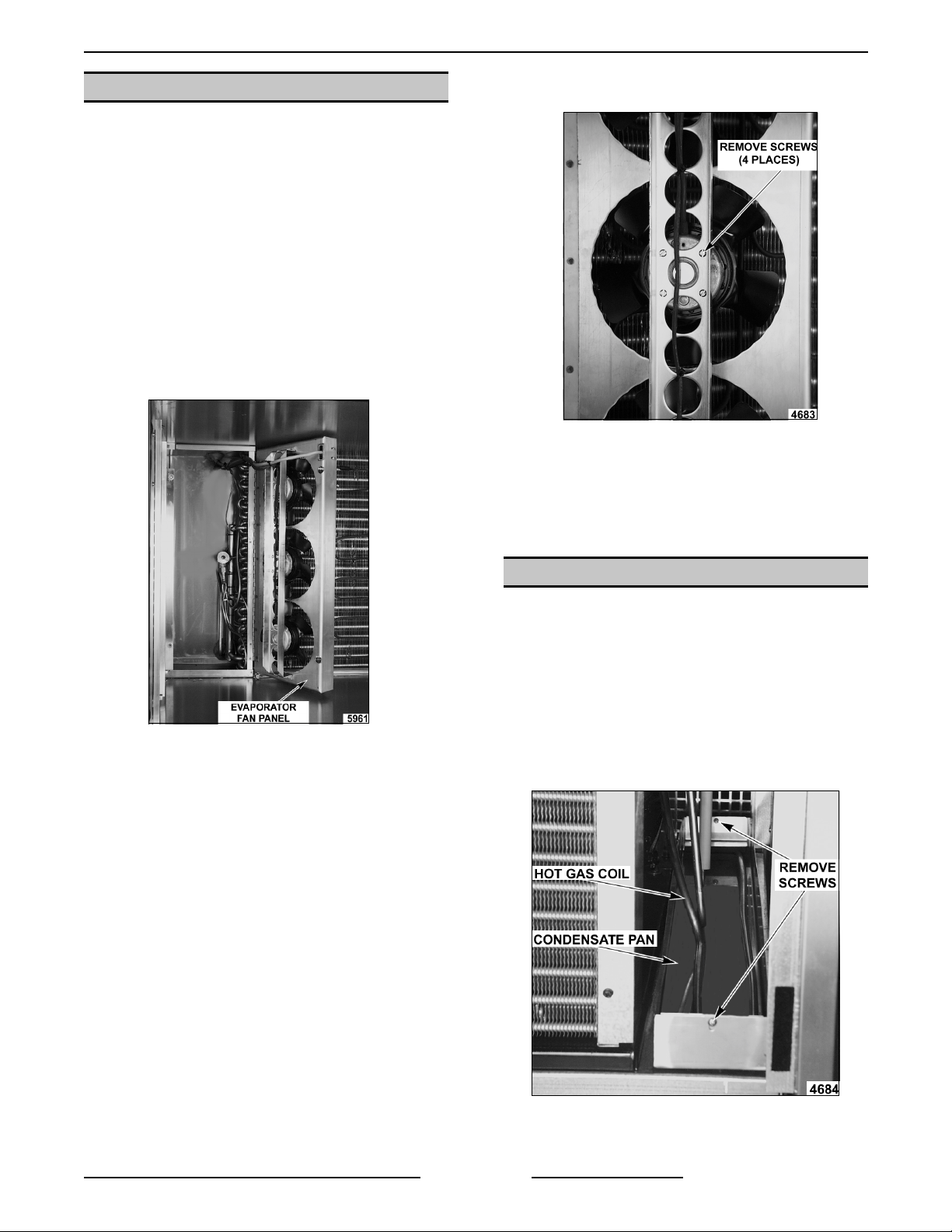
EVAPORATOR FAN
WARNING:
POWER TO T HE MACHINE AT THE MAIN
CIRCUIT BO X. P LA CE A TAG ON THE CI RCUIT
BOX INDICATING THE CIRCUIT IS BEING
SERVICED.
1. Remove the top and rear c overs as outlined
under “COVERS AND PANELS”.
2. Remove the tracks or shel ves fr om the cabinet
and remove the shelf clips from the left r ear
shelf support.
3. Remove the evaporator cover and open the
evaporator fan panel as out lined
under"COVERS A ND P A NE LS " .
DISCONNECT THE ELECTRICAL
5. Remove the bolts that secure the evaporator
fan from the housing panel.
6. Remove the fan from the cabinet.
CAUTION: Do not attempt t o disassembly motor
or remove fan blades from mo t or, blades are not
available as a service part.
7. Reverse the procedure to install.
4. Disconnect the lead wires at the junction box
on the top of the unit and pull them into the
cavity with the fan.
HOT GAS CONDENSATE PAN
1. Remove the condensing uni t cover as outlined
under “COVERS AND PANELS”.
2. Remove the bolts that secure the hot gas coil
from the pan.
CAUTION: Do not damage the coil during
removal.
3. Lift the hot gas coil out of t he pan.
4. Lift the hot gas pan to pull the Velcr o apar t
from the pan to the uni t.
5. Reverse proc edur e to install .
Form 24693 ( M ar c h 2001)Page 13 of 44
Page 14

HQC45/HQCF45/HQC90 QUICK CHI LLE R - S E RV ICE PROCEDURES AND ADJ U S TMENTS
SERVICE PROCEDURES AND A DJUSTMENTS
WARNING:
MEASUREMENTS WHILE THE POWER IS APPLIED TO THE MACHINE. EXERCISE EXTREME CAUTION AT
ALL TIMES. IF TEST POINTS ARE NOT EASI LY ACCESSIBLE, DISCONNECT POWER, ATTACH TEST
EQUIPMENT AND REAPPLY POWER TO TEST .
Expansion Valve
1. Access the expansion valve behind t he
evaporator fans.
2. Remove seal cap from the side of the
expansion valve.
3. Turn adjusting stem cloc k wise and seat valve.
4. Turn adjusting stem 2-1/2 t ur ns
counterclockwise. This is the initial setting.
5. Reassemble unit and c hec k for proper
operation.
Dual Pressure Co ntrol
CERTAIN PROCEDURES IN THIS SECTION REQUIRE ELECTRICAL TEST OR
REFRIGERATION CONTROL
ADJUSTMENTS
CPR Valve
Only fo r HQC45 ML124059, HQCF 45 ML124060,
HQC90 ML124063
1. Remove the rear condensing unit cover.
2. Remove the insulation fr om the valve.
1. Turn low pressure adjustm ent "cut-i n" screw to
10
the initial setting of
2. Turn diff adj ust ment screw to the initial setting
12
psi.
of
3. Turn high pressure adjustment "cut- out" screw
to the initial setting of
psi.
440
psi.
3. Connect the pressure gauge to the suct ion port
of the compressor.
4. Operate the cabinet with the door open or with
hot product.
5. Adjust the CPR valve so the maxim um
55
pressure is
psig.
4. Check for proper operation.
Form 24693 ( M ar c h 2001) Page 14 of 44
Page 15

HQC45/HQCF45/HQC90 QUICK CHI LLE R - S E RV ICE PROCEDURES AND ADJ U S TMENTS
TEV SUPERHEAT ADJUSTMENT
Introduction
Superheat is the heat that the refrigerant vapor absorbs above the boiling point. P r oper adjustment of the
superheat will optimize system performance.
Helpful Hints
• Adjustment s normally take 10-15 mi nutes before f ull impact on the system.
• 8-10 degrees F is a desirable superheat at coil out let.
• Check suction l ine temperature and discharge line temperat ure after any superheat adjustment.
Procedure
1. Access the expansion valve.
2. While the unit is cooling and evaporator fan panel c losed, take suction pressure at the compressor inlet or
(CPR valve outlet t ap were appl icable) and temperature readings at the outlet of the evaporator c oil.
NOTE:
3. Using the Temperature Pressure Chart, c onvert the pressure reading taken i n step 2 into a tem per ature.
4. Subtract t he converted temperat ur e from step 3 from the measured temperature in step 2. This is the
superheat.
A. To increase superheat, turn adjusting stem clockwise.
B. To decrease superheat, tur n adjusting stem c ounterclockwise.
WARNING:
POWER TO T HE MACHINE AT THE MAIN
CIRCUIT BO X. P LA CE A TAG ON THE CI RCUIT
BOX INDICATING THE CIRCUIT IS BEING
SERVICED.
WARNING:
USE OF REF RIGERANTS. B E CE RTAIN THE
WORK AREA IS WELL VENTILATED. SAFETY
GOGGLES AND GLOVES SHALL BE WORN
SINCE REFRI GERANTS MAY CAUS E B URNS TO
THE SKIN.
1. Access the refr igeration system.
NOTE:
current EPA guidelines.
The closer to the evaporator outlet, the more acc ur ate the readings.
TEMPERAT URE P RE S S URE CHA RT R-404A
Temperat ure in ° Fahrenhei t Pressure in lb/in²
F lb/in²
(
-41 4.0 -20 16.0 0 33.0 20 56.0 40 85.0
-35 7.0 -5 28.0 5 38.0 25 62.0 45 95.0
-30 10.0 -15 20.0 10 44.0 30 70.0 50 105.0
-25 13.0 -10 24.0 16 50.0 35 78.0 55 115.0
CHECKING FOR LEAKS
DISCONNECT THE ELECTRICAL
THIS PROCE DURE RE QUIRES THE
Recover remaining refrigerant based on
F lb/in²
(
F lb/in²
(
F lb/in²
(
2. Connect the low (blue) side of gauge manif old
to schrader valve.
3. Connect ref rigerant bottle to center of gauge
manifold and open valve on bottle to purge
hose to manifold gauge.
4. Open v alve on low side of gauge m anifol d and
charge system with a small amount of R-22
refrigerant (1 to 2 ounces).
5. Close bottle valve and gauge valve.
6. Disconnect refrigerant bottle and connect
nitrogen bottle.
7. Set output valve on nit rogen bottle t o equal the
appropriate pr essure, for the design rat ed
refrigerant at 100°F on the P/T chart .
NOTE:
See system data plate for desi gn r efrigerant.
F lb/in²
(
Form 24693 ( M ar c h 2001)Page 15 of 44
Page 16

HQC45/HQCF45/HQC90 QUICK CHI LLE R - S E RV ICE PROCEDURES AND ADJ U S TMENTS
8. Open nitrogen bottle valve and gauge manifold
valve (low side) and allow pressure to equalize.
9. Shut off both valves and disconnect the
nitrogen bottle.
10. Using a leak detector, check for leaks at all
tubing connect ions.
A. If any leaks are detected, r epair leak and
recheck f or leaks.
B. If no leaks are discovered, evacuate
system as outlined under " EVACUATING
SYSTEM".
NOTE:
future system diagnostic s.
11. Charge system as outlined under "CHARGING
Install a permanent hi gh si de ac c ess port for
SYSTEM".
EVACUATING SYSTEM
Introduction
Refri geration reclaiming equipment is required.
Our goal i n system ev ac uation is to remove all the
non-condensing contaminates as possible. No
evacuation met hod will remove 100% of the
moistur e and air from within t he r efrigeration cir c uit.
Because of this, guidelines and methods must be
developed and adhered to ensuring onl y har mless
amounts of c ontaminants remain i n the system.
Guidelines
• Use only a two stage vac uum pump (2 CF M or
greater) and el ec tronic m icron gauge.
• Set output valve on nitr ogen bottle to equal the
appropriate pr essure, for the design rat ed
refrigerant at 100°F on the P/T chart .
WARNING:
USE OF REF RIGERANTS. B E CE RTAIN THE
WORK AREA IS WELL VENTILATED. SAFETY
GOGGLES AND GLOVES SHALL BE WORN
SINCE REFRI GERANTS MAY CAUS E B URNS TO
THE SKIN.
1. Access the refr igeration system.
2. Connect low (blue) si de of gauge manifold to
schrader v alve on c ompressor access line and
high (red) side of gauge manifold to schrader
valve on filter/drier line.
NOTE:
permanent sweat on tap.
3. Connect center line of gauge manifold to
vacuum pump.
4. Turn vacuum pump on and open both sides of
gauge manifold.
5. Pull a vacuum to 200 mi c r ons.
6. Charge system and check for proper operat ion.
THIS PROCE DURE RE QUIRES THE
If t her e is no high side access, install a
CHARGING SYSTEM
WARNING:
POWER TO T HE MACHINE AT THE MAIN
CIRCUIT BO X. P LA CE A TAG ON THE CI RCUIT
BOX INDICATING THE CIRCUIT IS BEING
SERVICED.
WARNING:
USE OF REF RIGERANTS. B E CE RTAIN THE
WORK AREA IS WELL VENTILATED. SAFETY
GOGGLES AND GLOVES SHALL BE WORN
SINCE REFRI GERANTS MAY CAUS E B URNS TO
THE SKIN.
1. Access the refr igeration system.
DISCONNECT THE ELECTRICAL
THIS PROCE DURE RE QUIRES THE
• Evacuate from high and low sides of system.
• No chemical additive or alcohols are to be used
to "dry up" a system.
• Blow down of system with DRY NITROGEN
prior to evacuation is acceptabl e and many
times desirable. See "SYSTEM CLEAN UP".
• Evacuate to 200 mi c rons of merc ur y .
Procedure
WARNING:
POWER TO T HE MACHINE AT THE MAIN
CIRCUIT BO X. P LA CE A TAG ON THE CI RCUIT
BOX INDICATING THE CIRCUIT IS BEING
SERVICED.
Form 24693 ( M ar c h 2001) Page 16 of 44
DISCONNECT THE ELECTRICAL
2. Be sure refrigeration system is checked f or
3. Connect high side of gauge manifold to the
NOTE:
side to prevent liquid ref r igerant f r om reaching t he
compressor.
4. Connect ref rigerant bottle to center c onnec tion
5. Purge the hose fr om the refrigerant t ank to the
leaks and properly evacuated before chargi ng
as outlined under "LEAK CHECK" and
"EVACUATING SYSTEM".
liqui d line (make certain both valves on the
gauge manifold are closed).
Put ini tial char ge to system through the high
of gauge m anifol d (check the refrigerant bottle
to confirm direction for li quid).
manifold gauge.
Page 17

HQC45/HQCF45/HQC90 QUICK CHI LLE R - S E RV ICE PROCEDURES AND ADJ U S TMENTS
6. Open high side of gauge mani fold and al low
appropriate amount of r efrigerant to flow into
the refr igeration system.
A. Shut off gauge and bottle valves when this
has been accomplished.
7. Disconnect the hose from the r ec eiver valve.
8. Reconnect power to the unit and check for
proper operati on and high pressure leaks.
NOTE:
superheat and operating pr essures. Through low
side of system.
9. Disconnect power to the unit, repl ac e any
10. Reconnec t power to the unit.
Adjust charge as needed based on
panels and cov ers removed.
SYSTEM CLEAN UP
Introduction
When a r efriger ation system i s accessed in service,
some degree of system clean up i s required. There
are two levels of clean up:
• Basic - Conduct proc edur e as outlined under
"EVACUATING SYSTEM" and incorporating a
drier change, this is recommended only when
system exposure is limited.
• Massive - The use of Polyol Ester (POE) oil in
systems using R-134a and R-404a, as well as
in many other applic ations, require that ev er y
system failure be tr eated as a Massive cl eanup.
Massive Contamination
If a compressor burn out or failure has occurr ed, do
not install a new compressor until the clean-up
procedure has been completed.
If a massive moisture cont amination or POE oil
breakdown has occurred, rem ove the old
compressor as outli ned under "CONDENSING UNIT
COMPONENTS" in "REMOVAL AND
REPLACEMENT OF PARTS" dr ain the oil and hold
for installation.
1. Recover refri ger ant based on current EPA
guidelines.
2. Remove fi lter/drier and meter ing device.
NOTE:
assumed that the metering device is restricted after
a contamination. These devic es
clean and reused.
3. Flush high and low sides of refrigeration system
4. Reassemble refrigeration system to inc lude
NOTE:
system while welding is mandatory to prevent
oxidat ion/carbon pl ating that will lead to further
contamination.
In POE oi l applic ations, it shoul d always be
can not
with Nitrogen to displace any t r apped oil and
contaminates.
compressor, 032 size liquid line drier and new
metering device.
The use of low flow Nitrogen t hr ough the
be flushed
NOTE:
when moisture cont amination is present. The
suction dri er shoul d be r emov ed within 48 hours of
installation to prevent further performance issues.
Also instal l a new liquid line drier for maximum
system clean up.
5. Replace new oil into the compressor.
6. Purge system with Nitrogen f or 5 minutes.
7. Evac uate system f or 30 minutes.
8. Repeat steps 5 and 7 two additional times.
NOTE:
less.
9. Charge the system as outlined under
10. Replace any panels and covers removed.
11. Reconnec t power and check for pr oper
The use of a suction drier is recommended
Pressure should be applied t o the high side and
allowed to vent through the port on top of the
compressor.
The final vacuum should be 200 microns or
"CHARGING SYSTEM".
operation.
SERVICE MODE ML-124059,
ML-124060, ML-124063
The Service Mode allows service per sonal to
exerci se t he loads and monitor the input of the
Control i ndependently to det er mine if the Control,
the electr o-mechanic al components and the
refrigeration system are operating proper ly.
WARNING:
THE CONTROL BOX BE OPEN WHILE THE
POWER IS SUPPLIED TO T HE MACHINE.
EXERCISE EXTREME CAUTION AT ALL TIMES.
1. The unit must be in the idle mode.
2. Open the control box.
3. Locate the service switch on t he c ontrol board.
Push and hold the service switch, then push the
9 key on the keyboard. A maintenance menu
will be displayed.
THIS PROCE DURE RE QUIRES THAT
Form 24693 ( M ar c h 2001)Page 17 of 44
Page 18

HQC45/HQCF45/HQC90 QUICK CHI LLE R - S E RV ICE PROCEDURES AND ADJ U S TMENTS
Maintenance M enu = 1 = Inputs, 2 = Outputs, 3 = Clock, 4=Printer
INPUTS
Press
1 Front door switch on or off S tatus of input
yes External defrost on or off
yes External defrost on or off
yes Spare switch input on or off S tatus of input
yes AIR temp. - PROBE 1 - PROBE 2. PROBE 3 - PROBE 4 - COIL temp.
yes AIR temp. - PROBE 1 - PROBE 2. PROBE 3 - PROBE 4 - COIL temp.
yes Current Probe Not used
yes
no
Press
2 Defrost heater s = off 0 = off, 1 = on Watch LED 2 on control board
yes Evaporator fan = off 0 = off, 1 = on Watch LED 5 on control board
yes Solenoid valves = on 0 = off, 1 = on Watch LED 3 & 4 on control board
yes Freezer sol enoid = off 0 = off, 1 = on Watch Led 3 (Not used)
yes Remote alarm = off 0 = off, 1 = on Watch LED 1 on control board
yes Buzzer = off 0 = off, 1 = on Audible signal
yes
no
Return to front door switch
Maintenance M enu
Defrost heater s
Maintenance M enu
Display
(Top Line)
Display
(Top Line)
OUTPUTS
Display
(Bottom Line)
Display
(Bottom Line)
Explanation
Status of input
(Not used)
Status of input
(Not used)
Analog to di gital values
for probes
Fahrenheit values for
probes
Explanation
CLOCK
Press
3 Enter new time current ti me setting in memory.
yes Enter new time HR:MN:SC / 0 = AM 1 = PM
yes Enter new date current date setting in memory.
yes
no
Press 4 - Display will flash “SENDING TEST PATTERN TO PRINTER” and return to t he maintenance menu.
If t her e is an error in the pr int operati on, a message will be displayed.
If t he er ror occurs during the test print sequence, t hat error will only be displayed if print is selected again.
Form 24693 ( M ar c h 2001) Page 18 of 44
Enter new time
Maintenance M enu
Display
(Top Line)
Display
(Bottom Line)
PRINTER
Explanation
Use number keys to change t ime
(hrs/ mins/sec)
Use number keys to change dat e
(mo/day/yr)
Page 19

HQC45/HQCF45/HQC90 QUICK CHI LLE R - S E RV ICE PROCEDURES AND ADJ U S TMENTS
SERVICE MODE
ML-124066, ML-124067,
ML-124068
The Service Mode allows service per sonal to exercise the loads and monitor the input of the Control
independently to determine if the Control, the electro-mechanical components and the r efrigeration system are
operating proper ly.
WARNING:
SUPPLIED TO THE MACHINE. EXERCISE EXTREME CAUTION AT ALL TIMES.
CAUTION: Electro-static discharge will damage the control board. Use a anti-static grounding kit when
servicing t he computer control b ox.
1. Turn power off to the uni t.
2. Loosen the control panel screws and swing open control panel to gain access to servi c e mode switch.
THIS PROCE DURE RE QUIRES THAT THE CONTROL BO X BE OPEN WHILE THE POWER I S
3. Locate the service mode switch on the back of
control boar d, press and hold switch while
turning power ON to chiller. The following
menu will be displayed.
NOTE:
power OFF and back O N to display user main
menu.
To exi t the serv ice mode at any time, turn
LAST DATE OF SERVICE
00/00/00
< UPDATE
< SET CLOCK NEXT >
A. Pressing the button besi de UP DA TE sets
last date of service date to current date. If
date is INVALID, set clock to current date
and tim e.
B. SET CLOCK - Displays set clock menu to
change the last date of service.
SET CLOCK MONTH
XX/XX/XX XX:XX
< BACK NEXT>
< CANCEL ENTER
1) Pr essing the button beside BACK or
NEXT toggles through sel ec tion
options:
MONTH/DAY/YEAR/HOUR/MINUTE.
2) Pr essing the button beside the up or
down arrows changes the selected
date or time numbers.
3) Pr essing the button beside ENTE R
saves the new date and time selected
and displays on the l ast date of
servi ce menu.
4) Pr essing the button beside CANCEL
does not save any change to date or
tim e and return to the last date of
servi ce menu.
Form 24693 ( M ar c h 2001)Page 19 of 44
Page 20

HQC45/HQCF45/HQC90 QUICK CHI LLE R - S E RV ICE PROCEDURES AND ADJ U S TMENTS
C. NEXT- With the last date of service menu
displayed, pr essing t he button beside
NEXT the following service m enu will be
displayed.
< SERVICE MENU DOOR >
< REFR/AIR DEF/COIL >
< PROBES/ALARM FANS >
< PRINTER DISPLAY >
NOTE:
From service menu, the following Ser vic e
modes can be selected:
• SERVICE MENU - Diagnostic test.
• REFR/AIR - Refriger ation System and A ir
probe test.
• PROBES/ALARM - View current probes
reading and change status of ALARM output.
• DISPLAY - Illuminates entire display.
• DOORS - Displays status (OPEN or CLOSED)
• DEF/COIL - Defrost System and Coil probe
test.
• FANS - Tests Fan outputs
• PRINTERS – Sends test pattern to printer(s).
D. SERVICE MENU - Diagnostic test.
< DIAGNOSTIC MAXIMUM >
< RUN CYCLES MINIMUM >
< SINCE DEF. FAILURE >
CYCLES
CLEAR >
5) Pr essing the button beside MINIMUM
displays (in the lower lef t corner of
the display) the minimum air
temperat ure in cabinet .
6) Pr essing the button beside FAILURE
displays (in the lower lef t corner of
the display) the failure since last
servi ce cleared. I f there i s more than
one failure, pressing the lower left
button will cycle through all failures.
Below is a complete list of all possible
failures.
DEFR HEAT= Defrost heater
malfunction.
SYSTEM FAIL= Chiller not cooling
properly.
OVER TEMP= Internal air
temperat ure exceeds 150°F.
CONTROL= Control board
malfunction.
INTERRUPTE D= A chilling cycle has
been interrupted either by loss of
main power or inadvertently switching
power switch OFF.
PROBE= One of the probes have
malfunctioned: Air, Coil, or Pr oduc t.
PRINTER= P r inter not responding or
out of paper/label.
7) Pr essing the button beside CLEAR
clears the curr ent item .
E. REFR/AIR – Refrigeration System and A ir
probe test.
NOTE:
The selected item will have a flashing "<" or
">" beside it.
1) Pr essing the button beside
DIAGNOSTIC returns to the service
menu.
2) Pr essing the button beside RUN
CYCLES displays (in the lower left
corner of the display) t he number of
cycles ran since last cleared.
3) Pr essing the button beside SINCE
DEF. displ ays (in the lower left corner
of the display) the number of cycles
ran since last defrost.
4) Pr essing the button beside
MAXIMUM displays (in the lower left
corner of the display) t he maxi mum
air temperature in c abinet.
Form 24693 ( M ar c h 2001) Page 20 of 44
REFRIGERATION TEST:
< REFR: OFF
AIR TEMP: 14°F
< COMP USAGE BACK>
1) Pr essing the button beside REFR c an
test the com pressor function. The
options for the REFR are: O FF, ON,
or ON&FANS.
OFF= Refrigeration not operational.
ON= Refrigeration operational .
ON&FANS= Refri ger ation and
evaporator fans operational.
2) T he c urrent Air temperature inside
the cavity i s also displayed.
Page 21

HQC45/HQCF45/HQC90 QUICK CHI LLE R - S E RV ICE PROCEDURES AND ADJ U S TMENTS
3) T he servic e menu can be reached by
pressing the button beside B A CK and
all outputs will return to their off state.
4) COMP USAGE – Displays days &
hours since the last cleaning of
condensor coil.
NOTE:
After c leaning the condensor coil,
press the button beside cl eaned c oil to
reset the day & hour bot h to read 0.
5) T he pr evious menu can be reached
by pressing the button besi de B A CK
and all outputs will return to their off
state.
F. PROBES/ALARM – View curr ent probes
reading and change status of ALARM
output.
PRODUCT P ROBE TEMP S :
1 74°F 73°F 3
2 73°F
< ALARM = OFF BACK>
1) T his screen displays the value of
each product probe. If no value(s)
shown find the source of the problem.
2) T he alarm out put can also be
changed from OFF to ON.
3) Pr essing B A CK displays the serv ice
menu and the al arm output r eturns to
the off state.
G. DISPLAY – Illuminates entire display, see
below. Pressing any key will return to the
servi ce menu. This option can also be
used as a test for the key pad, since any
key press will return to the previous menu.
H. DOORS – Displays status (OPEN or
CLOSED).
DOOR INPUTS:
OPEN/CLOSED
BACK >
NOTE:
Cycling the door open and closed shows the
status of compartment door. If not find the source of
the problem.
1) Pr essing B A CK displays the serv ice
menu.
I. DEF/COIL – Defrost System and Coil
probe test.
DEFROST TEST:
< HEATER = OFF
COIL TEMP = 76°F
BACK >
1) T he defrost heat can be turned OFF
or ON by pressing the heat er button.
OFF= Defrost heater should not be
energize.
ON= Defrost heater should energi z e
and coil t emperature should sl owly
increase.
2) T he c oil temperature is al so
displayed. If not find the source of the
problem.
NOTE:
If t he screen does not display as shown
display board needs repl ac ed. If display does not
return to the servic e menu then keypad needs
replaced.
3) Pr essing B A CK displays the serv ice
menu and turns the heater off.
Form 24693 ( M ar c h 2001)Page 21 of 44
Page 22

HQC45/HQCF45/HQC90 QUICK CHI LLE R - S E RV ICE PROCEDURES AND ADJ U S TMENTS
J. FANS – Tests Fan out puts.
FAN MODE TE S T:
< FAN = NONE
FAN DOOR = CLOSED
1) Pr essing the FANS button test the
evaporator fans f unction. T he options
for FA NS ar e: NONE, SET 1, SET2
and BOTH.
NONE= All evaporator f ans deenergized.
SET1= T his is the low air flow mode
for the soft chill mode. Only one
evaporator fan energized. If not find
the source of t he problem.
SET2= T wo evaporator fans
energized. I f not find the source of
the problem.
BOTH= A ll evaporator fans
energized. I f not find the source of
the problem.
2) Pr essing B A CK displays the serv ice
menu and turns the fan(s) off.
BACK >
K. PRINTERS – Sends test print out t o
printer(s).
PRINTER TEST:
< RECORD: READY
< LABEL: READY
NOTE:
is not an option.
LABEL: READY not displayed i f label printer
1) Pr essing t he button beside RECORD
sends a test print out t o the paper
printer. The READY changes to
RUNNING, then t o SUCCESS if the
print finishes successfully. Other wise
ERROR is display ed and find the
source of the pr oblem.
2) I f the Label pr inter option is installed,
the LABEL test can be ran by
pressing the button beside LABEL to
send a test print out .
3) Pr essing B A CK displays the serv ice
menu.
BACK >
FACTORY SETTINGS MODE
ML-124066, ML-124067,
ML-124068
WARNING:
SUPPLIED TO THE MACHINE. EXERCISE EXTREME CAUTION AT ALL TIMES.
CAUTION: Electro-static discharge will damage the control board. Use a anti-static grounding kit when
servicing t he computer control b ox.
1. Turn power OFF to the unit.
THIS PROCE DURE RE QUIRES THAT THE CONTROL BO X BE OPEN WHILE THE POWER I S
Form 24693 ( M ar c h 2001) Page 22 of 44
Page 23

HQC45/HQCF45/HQC90 QUICK CHI LLE R - S E RV ICE PROCEDURES AND ADJ U S TMENTS
2. Loosen the control panel screws and swing open control panel to gain access to factor y settings mode
switch.
3. Locate the factory settings mode switch on the back of display board, press and hold switch while tur ning
power ON to chiller. The following factory settings menu will be displayed.
FACTORY SETT I NGS
VERSION:
S/N:
<RESET NEXT>
BACK DOOR [NO]
LABEL PRINTER [NO]
FAN IN HLD [CYCLE]
<BACK NEXT>
BLASTING DIFF [4]
HOLDING DIFF [4]
((F
((F
ANTI-SHORT [3]
<BACK NEXT>
DEFROST TIME [20]
DEFR. TEMP [50]
DEFR. INTVL [6] HR
((F
<BACK NEXT>
4. Enter the uni ts serial number by sel ec ting the left arrow nex t to
changes which digit to edit in serial number, and the up arrow increments
the v alue of the sel ected digit.
RESET- Resets all the parameters to the factory preset values, and
erases all recorded cycles in memory.
NEXT- Continues to the next factory setting menu.
5. BACK DOOR- Is not an option, selec t no.
6. LABEL PRINTER- Options are:
OFF= No label printer.
ON= Individual label s.
CNT= Continuous labels.
7. FANS IN HLD- [CYCLE] F ans are defaulted to cycle ON and OFF.
Select [ C ONT] f or c ontinuous fan operat ion during hold mode.
8. BLASTING DIFF- Blasting different ial is the t emperature difference
between the set point t emperature and the ac tual tem per ature for opening
the compressor solenoid when in chill or freeze mode.
9. HOLDING DIFF- Is the temperature di ffer enc e for hold mode.
10. ANTI SHORT- Is the minimum time bet ween cl osi ng and opening the
compressor solenoid.
11. DEFROST TI M E - Is the length of defrost t ime in minutes.
12. DEFROST TEM P - Is the set point for the coil temperature.
13. DEFROST INT V L- Is the time interval bet ween automatic defrosts.
S/N
ENTER SE CURITY CODE
FOR NEXT SETTINGS:
[0000000]
<EXIT ENTER>
INCORRECT CODE!
PLEASE CALL HOBART
FOR ASSISTANCE
NEXT>
MACH. MODEL [HQC]
MACHINE SIZE [45]
SOFT FREEZE [NO]
<BACK NEXT>
14. T he security code is t he last seven di gits of the serial number reversed.
The left arrow selects which digit to adjust, and the up arrow increments
the v alue of the selected digi t.
15. Pr ess Enter to continue to secur ed options or Exit to exit the factory
settings mode.
16. I f the inc or r ec t security code was entered, the following screen will be
displayed.
17. MA CH. MODEL- Sel ec t the type of model either HQC or HQCF
NOTE:
18. MA CHINE SIZE- S elect the machine size ei ther 45 or 90
NOTE:
Do not select HQF, FQC, FQF, or F QCF model s.
Do not select any other size than actual chiller size.
19. SOFT FREEZE- Allows chiller to perform a soft freeze.
NOTE:
This should remain NO unless instruc ted otherwise.
Form 24693 ( M ar c h 2001)Page 23 of 44
Page 24

HQC45/HQCF45/HQC90 QUICK CHI LLE R - S E RV ICE PROCEDURES AND ADJ U S TMENTS
FREEZE MAX [20]
SFT FRZ MIN [-5]
DEFROST TYPE [EL E]
<BACK NEXT>
((F
((F
20. F RE E ZE MAX- Is the maximum selectable value for freezing t he HQCF
model chiller.
21. SOFT FRZ M IN- Is the minimum selectabl e value for soft freeze.
22. DEFROST TYPE- Is selection for chiller to defrost by [ELE] (defrost
heating element) or [ GAS] (refrigeration compressor).
NOTE:
This should remain [ELE] unless instructed otherwise.
FACTORY SETT I NGS
DO YOU WISH TO SAVE
THESE NEW SETT I NGS?
<NO YES>
SAVING SETTINGS
PLEASE WAIT. . .
FACTORY SETT I NGS
SETUP IS COMPLETE!
RESTART CONTROL LER
23. YES- Sav es the settings to memory.
24. NO - E xit wit hout saving c hanges.
25. This display will be shown while the settings are being saved.
26. When the sett ings have been saved, restart the controller by turning
power OFF then back ON.
SOFTWARE VERSION
ML-124059,ML-124060,ML-124063
SOFTWARE VERSION
ML-124066,ML-124067,ML-124068
The control program sof tware version can be
determined by pressing the 0 key when the m ain
menu is displayed. The displ ay will show "REV 2.1";
“MODEL2"; “PUSH 0 TO EXIT”.
version)
on the E-Prom. The E-Pr om is locat ed on the
control boar d in the control box.
IMPORTANT NOTE:
could af fect the oper ation of the Chiller.
check the software version before servicing t his unit
or calling for technical assistance.
Form 24693 ( M ar c h 2001) Page 24 of 44
The version will match the version printed
Any change in the software
(2L is the current
ALWAYS
The control program sof tware version is displayed
during initial ization when unit is turned on. The
display will show the chiller model number and the
current sof tware version number.
Smart Chill
HQC 45 or 90
INITIALIZING
VERSION: X.XX
Page 25

HQC45/HQCF45/HQC90 QUICK CHI LLE R - S E RV ICE PROCEDURES AND ADJ U S TMENTS
CONTROLLER SERVICE
PROCEDURES
ML-124059,ML-124060,
ML-124063
Control ler Board
The control ler board has a series of LEDs to assist
in troubl eshooting. When the LED is l it, the
component should be energized.
LED COMPONENT LED COMPONENT
1 Remote Alarm 5 E vaporator Fan
2 Defrost Heater 6 Controller*
3 NOT USED 7 NOT USED
4 Refrigeration
Solenoid
*LED #6 blink s on and off at one second intervals
when the controller board is energized.
The service switch is loc ated near the center of the
board. The buzzer loudness pot is located near t he
center of the board, below the buzzer .
8 NOT USED
Voltage check for +5VDC to Printer Board
1. Check for +5 VDC on pins J3-15, J3- 16, J3-17.
2. Check for 0V on pins J3-18, J3-19, J 3- 20.
Voltage check for +5VDC to Display.
1. Check for +5VDC between J1-1 and J1-2 on
controller board.
2. Check these pins at cable connections J1 and
P1.
Printer Board
The printer board monitors the speed of the paper
feeding through the printhead.
If t he speed i s not nor mal, “Pri nter Error” i s shown
on the display. A paper jam or a mechanical
problem wi th the printer c an be the cause.
To reset the printer you must r emov e the power
from the unit for a minimum of five seconds. If the
power is removed from the unit for less than ten
minutes, it will return to the point in the cycle at
which the int er r uption occurred.
.
Voltage check for 13.5 (±1.5) VDC to Control ler
Board if LED 6 is not flashing.
1. Check between TP 8 & 9 on hi gh voltage board
for 13.5 V DC.
2. Check the cable connections between the high
voltage board and the controller board.
A. Pins 5 & 6 are ground on J2 (high voltage
board) and J6 (contr oller board).
B. Pins 3 & 4 are +12VDC on J 2 ( high
voltage board) and J6 (controller boar d) .
C. Check these pins at cable connections
P17, J10/P10, P 9/J9, and P6.
1. Inspect the printer for a paper jam or roll
feeding incorrectly.
2. Remove the paper f rom the printer and reload
the paper.
3. Reset the controller and try to print.
4. If t he er ror occurs again and its not a paper
problem, replace the pr inter board.
Form 24693 ( M ar c h 2001)Page 25 of 44
Page 26

HQC45/HQCF45/HQC90 QUICK CHI LLE R - S E RV ICE PROCEDURES AND ADJ U S TMENTS
Keypad
1. Disconnect P2 from J2 on the controller board.
2. Perform a conti nuity test between the pin numbers (P2) for the appropriate key.
3. Use the 200 scale on a digi tal met er . When the key is pressed, the readi ng shoul d be between 15 and 40
ohms.
Power/Hi gh Voltage Board
The power board has a series of LEDs lamps and
test points to assist in troubleshooti ng.
When the LED or lam p is lit, the component shoul d
be energized.
LAMP
L1 Refrigeration
L2 Evaporator
LED COMPONENT LED COMPONENT
1 Power Board 3 NOT USED
2 Remote Alarm
COMPONENT LAMP COMPONENT
L3 Heater control
Solenoid
L4 NOT USED
Fan
TEST
COMPONENT VOLTAGE
POINT
1 L2 Supply Vol tage
2 Neutral Line 0 V
3 Local Solenoid 120 V
4 Fan Control 120 V
5 Heater Control 120 V
6 Remote S olenoid 120 V
7 Not Used
8 Print er & Controller + 12 V
9 Chassis & Signal
0 V
Ground
10 L1 Supply Voltage
Form 24693 ( M ar c h 2001) Page 26 of 44
Page 27

HQC45/HQCF45/HQC90 QUICK CHI LLE R - S E RV ICE PROCEDURES AND ADJ U S TMENTS
CONTROLLER SERVICE
PROCEDURES
ML-124066, ML-124067,
ML-124068
Control ler Board
The control ler board has two LED's to assist in troubleshooting. LED (D2 P OWER) is lit= indic ates that power is
supplied to the controll er boar d. LED (D1) is f lashing= indicates that I/O board and control board are
comm unicating. If not , check all har ness connections to communication cables going between I/O & controller
boards. LED (D13) is not used.
Form 24693 ( M ar c h 2001)Page 27 of 44
Page 28

HQC45/HQCF45/HQC90 QUICK CHI LLE R - S E RV ICE PROCEDURES AND ADJ U S TMENTS
I/O Board
The I/O board has a series of LED's and test points to assist in troubleshooti ng. When the LED is li t, the
component should be energized or input open.
LED COMPONENT LED COMPONENT TEST
POINT
COMPONENT VOLTAGE
D1 F r ont Door D8 Defr ost Heater TP1 Relays +12VDC
D2 NO T USED D9 Low Fan TP 2 Logic Circuit +5VDC
D3 F an Door D10 High Fan TP3 Ground 0V
D4 Compressor
Solenoid
D11 Alarm J17, J18 Triac Compressor
Solenoid
0.75 - 2VAC
voltage drop
J15, J16 Triac Defrost Heater 0.75 - 2V A C
voltage drop
NOTE:
Voltage drop readings to be measured
while specified com ponent is energized.
Form 24693 ( M ar c h 2001) Page 28 of 44
Page 29

HQC45/HQCF45/HQC90 QUICK CHI LLE R - E LE CTRICAL OPERATION
ELECTRICAL OPERATION
COMPONENT LOCATION
Only fo r HQC45 ML-124059, HQCF45 ML-124060, HQ C90 M L-124063
Form 24693 ( M ar c h 2001)Page 29 of 44
Page 30

HQC45/HQCF45/HQC90 QUICK CHI LLE R - E LE CTRICAL OPERATION
Only fo r HQC45 ML-124066, HQCF45 ML-124067, HQ C90 M L-124068
Form 24693 ( M ar c h 2001) Page 30 of 44
Page 31

HQC45/HQCF45/HQC90 QUICK CHI LLE R - E LE CTRICAL OPERATION
COMPONENT FUNCTION
Compressor ...............
Condenser Fan ............
Dual Pressure Co ntrol .......
Start Capacitor.............
Run Capacitor .............
Thermal Overload ..........
Relay ....................
Evaporator Fan ............
Defrost Heater .............
Air Temperature Sensor .....
Coil Temperature Sensor ....
Food Temperature Probe ....
Front Door Switch ..........
Fan Door Switch ...........
Solenoid Valve.............
Door Perimeter Heater.......
Door Heater Thermostat .....
Controller.................
Power Supply Boards .......
I/O Board .................
Main Contactor ............
Main Switch ...............
Over Temp . Thermo st at
(manual reset) .............
Safety Thermostat
(manual reset) .............
Pumps ref rigerant thr ough r efrigeration li nes and components.
Draws air across condenser coil to aid in removing heat from the refrigerant
and moves air across compressor to aid in cooling the compr essor.
Low side monitor s suction pressure at compressor. Shut s compressor off
when low pressure setting is reached (cut-out). Al lows compressor to run
when pressure rises to cut-in setting.
High side monitors discharge pressure at compressor. Shuts compr essor off
when high pressure setting is reached (c ut-out). Allows compressor to run
when pressure returns to cut-in sett ing.
The differential is the difference in pressure between opened and closed
states of the pressure switch.
Wired in series with the start windings to help start compr essor m otor .
Continually in circuit t o help compressor motor during operat ion.
Removes power from c ompressor if the internal temperatur e of the
compressor becom es too high (auto reset).
Senses current of r un winding of compressor motor. Nor mally open c ontacts
close when the run winding draws a high am per age at start and brings the
start capaci tor and start windings into the circ uit. As the motor reaches
operating speed (l ess amper age through run winding), the normal ly open
contacts open and removes the start capacitor and star t windings from the
circuit.
Draws air from the cabinet and mov es the air through the evaporator c oil. Air
should blow air toward the door .
Defrosts evaporator coil and prevents water droplets from evaporator coil
from freezing before t hey c an dr ain to the condensate pan. Operates only
during defrost cycle.
Monitors ai r temperature inside cabinet.
Monitors the suction l ine temperature at evaporator duri ng defrost cycle.
Monitors temperature of food product .
Monitors door for open or closed posit ion. Evaporator fans stop when door is
open.
Monitors evaporator fan compartment door for open or closed position.
Evapor ator fans will not start if the switch is open. Refrigerant system
operation stops after 30 seconds switch has been open.
Normally closed. When energi z ed ,allows refrigerant to flow from receiver to
evaporator coil .
Prev ents condensate from forming on door f r ame.
Monitors door frame t emperature. Opens circuit to door frame heater if the
door frame temper ature exceeds the set poi nt.
Performs the following f unc tions:
A. Displays all data for the current mode of operation.
B. Cycles refrigeration system to maintain cabinet temperature.
C. Monitors power failures.
D. Monitors door positi on.
Controls power to I/O board and printer(s).
Performs the following f unc tions:
A. Cycles defrost heaters during defrost cycle.
B. Cycles compressor solenoid to maintain c abinet tem perature.
C. Monitors AC monitor to determine loss of power.
D. Closes alarm contact to signal external al ar m dev ice, af ter a malfuncti on
detected.
E. Monit ors door switch position.
F. Monitors fan door switch.
Controls power to unit electrical cir c uits once main switch is closed.
Controls power to m ain contactor when safety thermostat is closed.
Removes power from all com ponents including the controller.
Monitors cabinet air temperature. Opens circuit to main c ontactor if cabinet
temperat ure exceeds 155°F.
Monitors cabinet air temperature. Opens circuit to main c ontactor if cabinet
temperat ure exceeds 155°F.
Form 24693 ( M ar c h 2001)Page 31 of 44
Page 32

HQC45/HQCF45/HQC90 QUICK CHI LLE R - E LE CTRICAL OPERATION
SEQUENCE OF OPERATION
ML-124059, ML-124060,
ML-124063
NOTE:
(ML-124063) schematics will be used to explain the
electrical sequence of oper ation.
Refrigeration System
1. The controller must be in a chill or hold mode.
2. The controller monitors the air temperature and
3. The low pressure switch closes with the rise in
4. The expansion valve m onitors the evaporator
5. The controller senses the air temperature
6. Compressor conti nues to r un. Low pressure
7. Unit is cycled by controller.
Idle Mode
1. Conditions
2. Main switch closed.
3. Controll er goes through power up self
HQC45 (ML-124059,ML-124060) HQC90
senses a need for cooling.
A. The relay that control s the sol enoid valve
is energized.
1) Solenoid valve is energized and
refrigerant f lows to the evaporator.
pressure.
A. The compressor motor is energiz ed and
refrigerant is pum ped through the system.
superheat and meter s the amount of r efrigerant
entering the evaporator.
requirements have been met.
A. De-energizes the relay that cont r ols the
solenoid valve.
1) Solenoid valve is de-energiz ed and
closes. Refr igerant f low to the
evaporator stops.
control opens as pressure drops.
A. Compressor mot or de- ener gized.
A. Unit connect ed to correct volt age.
B. Safety thermostat c losed.
C. Fan door switch c losed.
D. Front door switch closed.
A. Main contactor energized, c ontacts close.
1) Door heater energized.
2) Cont r oller energized.
3) Power to condensing unit cont r ols.
diagnostics and di spl ay s main menu.
Hold Mode
1. Unit is i n IDLE mode.
2. Hold mode is selected.
NOTE:
run. One tracks the time in the hold mode and the
other track s the time sinc e the last defr ost ( hold
mode has a defrost every six hours).
NOTE:
set-up menus.
NOTE:
operation, the evaporator fans and refrigeration
system will shut down.
3. Hold mode is termi nated by pressing the stop
NOTE:
operator with the def rost cycle in progress, the
defrost mode will continue until completion before
going into IDLE MODE.
Manual Chiller / Freezer Mode
1. Unit is i n IDLE mode.
2. Manual chill is selected and a tim e is entered.
3. For the first 2/3 of the chilling time, the
4. For the last 1/3 of the cycle, if “surface
NOTE:
chill operation, the evaporator fans and refri ger ation
system will shut down.
When the hold mode is selected, two ti mers
A. The refrigeration system will cycle on the
air temperature of the cabinet.
1) “On” at t he set point plus differ ential.
2) “Off” when set point reached.
Set point and differential are selected i n the
If t he c abinet door is opened during
B. The hold m ode has an aut omatic defrost
cycle aft er every six hours of operation in
the hold m ode.
1) When the defrost cycle is complete
and the unit returns to the hold mode,
the ev apor ator fans will not operate
until the coil temperature is below
25°F.
key.
If t he HOLD MODE is terminated by the
A. Unit reverts back to st ep 2.
refrigeration system will cycle on the blasting
air temperature set point.
A. “On” at the set point pl us di ffer ential.
B. “Off” when set point reac hed.
protection” has been selected, the refrigerat ion
system will cycle on the new blasting air
temperat ure set point of 28(F. If “surface
protection” is not selected, the set point
remains the same unt il the end of the cycle.
If t he c abinet door is opened during manual
Form 24693 ( M ar c h 2001) Page 32 of 44
Page 33

HQC45/HQCF45/HQC90 QUICK CHI LLE R - E LE CTRICAL OPERATION
5. Manual chill mode is terminated when time
expires.
A. Buzzer sounds for 2 minutes.
6. If t he end of the m anual chill cycle is not
acknowledge by pressing the yes key, the unit
will enter the hold mode.
A. If t he end of the m anual chill cycle is
acknowledge by pressing the yes key, the
unit will enter the idle mode.
Automatic Chiller / Freezer Mode
1. Unit is i n IDLE mode.
2. Automatic chill is selected.
NOTE:
chill operation, the evaporator fans and refri ger ation
system will shut down.
3. Auto chill mode is terminated when all the
NOTE:
temperat ure of each probe as they r eac h the set
temperat ure and the buzzer sounds for 2 minutes
(unless the MUTE key is pressed).
Defrost Mode
1. The defrost mode can be entered manually
2. Defrost cycle is 20 minutes i n length or until the
NOTE:
evaporator fans will not operate until the c oil
temperat ure is below 25°F.
Operational Mode Error Codes
If t he c abinet door is opened during manual
product probes reach the target chill
temperature.
An asterisk will be displayed next to the
A. If t he end of the automatic ch ill cycl e i s not
acknowledge by pressing the yes key, the
unit will enter the hold mode.
B. If t he end of the automatic ch ill cycl e i s
acknowledge by pressing the yes key, the
unit will enter the idle mode.
from the idle mode or automatical ly from the
hold mode.
coil t emperature reac hes 50°F.
A. If t he defrost mode was entered from t he
hold mode, the unit will return to the hold
mode.
When the unit returns to the hold m ode, the
B. If t he defrost mode was entered from t he
idle mode, the buzzer sounds f or two
minut es unless the yes key or the mute
key is pressed.
MESSAGE EXPLANATION
Printer Error Paper speed too slow
Cooling too slow Air temperature can not be
greater than 44°F 30 minutes
into the hold cycle.
SEQUENCE OF OPERATION
ML-124066, ML-124067,
ML-124068
NOTE:
HQC90 ML-124068 schematics will be used to
explain the electrical sequence of operation.
Refrigeration System
1. The controller must be in a chill or hold mode.
2. The controller monitors the air temperature and
3. The low pressure switch closes with the rise in
4. The expansion valve m onitors the evaporator
5. The controller senses the air temperature
6. Compressor conti nues to r un. Low pressure
7. Unit is cycled by controller.
Idle Mode
1. Conditions
2. Main switch closed.
3. Controll er goes through power up self
HQC45 ML-124066, HQCF45 ML-124067,
senses a need for cooling.
A. The relay that control s the sol enoid valve
is energized.
1) Solenoid valve is energized and
refrigerant f lows to the evaporator.
pressure.
A. The compressor motor is energiz ed and
refrigerant is pum ped through the system.
superheat and meter s the amount of r efrigerant
entering the evaporator.
requirements have been met.
A. De-energizes the relay that cont r ols the
solenoid valve.
1) Solenoid valve is de-energiz ed and
closes. Refr igerant f low to the
evaporator stops.
control opens as pressure drops.
A. Compressor mot or de- ener gized.
A. Unit connect ed to correct volt age.
B. Safety thermostat c losed.
C. Fan door switch c losed.
D. Front door switch closed.
A. Main contactor energized, c ontacts close.
1) Door heater energized.
2) Cont r oller energized.
3) Power to condensing unit cont r ols.
diagnostics and di spl ay s main menu.
Form 24693 ( M ar c h 2001)Page 33 of 44
Page 34

HQC45/HQCF45/HQC90 QUICK CHI LLE R - E LE CTRICAL OPERATION
Hold Mode
Product can be held at chil led temperature by
selecting hold mode from m ain menu. Unit will also
go into hold mode automatically when all active
probes have reac hed the target temperature when in
"By Temp" mode. I f a "By T ime" mode selected the
unit enters hold mode automatical ly aft er the tim e
has expired.
1. Unit is i n IDLE mode.
2. Hold mode is selected.
NOTE:
When the hold mode is selected, two ti mers
run. One tracks the time in the hold mode and the
other track s the time sinc e the last defr ost ( hold
mode def r ost s at a pr ogr amable interval).
A. The refrigeration system will cycle on the
air temperature of the cabinet.
1) “On” at t he set point plus differ ential.
2) “Off” when set point reached.
NOTE:
Set point and differential are selected i n the
factor y set - up menus.
NOTE:
If t he c abinet door is opened during
operation, the evaporator fans and refrigeration
system will shut down.
B. The hold m ode has an aut omatic defrost
cycle after a programable interval of
operation i n the hold mode.
1) When the defrost cycle is complete
and the unit returns to the hold mode,
the ev apor ator fans will not operate
until the coil temperature is below
25°F.
3. Hold mode is termi nated by pressing the exit
key.
NOTE:
If t he HOLD MODE is terminated by the
operator with the def rost cycle in progress, the
defrost mode will continue until completion before
going into IDLE MODE.
A. Unit reverts back to st ep 2.
"By Time" Chiller / Freezer Mode
1. Unit is i n IDLE mode.
2. Chill type is selected and a cycle tim e is
entered then start k ey pr essed.
3. The refrigeration system will cycle on the
blasting air temperature set point.
A. “On” at the set point pl us di ffer ential.
B. “Off” when set point reac hed.
4. If “soft chill” has been selected, the
refrigeration system will cycle on the new
blasting air temperature set point. If “chill” was
selected, the set point remains the same until
the end of t he cycle.
NOTE:
If t he c abinet door is opened during By Time
chill operation, the evaporator fans and refri ger ation
system will shut down.
5. Chill mode is terminated when time expires.
A. Buzzer sounds until muted.
6. At the end of the chill cycle the unit will enter
the hold m ode.
A. If t he end of the chill cycle is acknowledge
by pressing the stop/reset key , the unit will
enter the idle mode.
"By Temp" Chiller / Freezer Mode
1. Unit is i n IDLE mode.
2. Chill type is selected and a target tem per ature
is entered then start key pressed and probe
selected.
3. The refrigeration system will cycle on the
blasting air temperature set point.
NOTE:
If t he c abinet door is opened during By
Temp chill operation, t he evaporator fans and
refrigeration system will shut down.
4. Chill mode is terminated when all the product
probes reach the target c hill temperature.
NOTE:
Once the temperature of the probe reaches
the target temperature display will alternate with
"DONE", and the buzzer will sound unless muted.
A. At the end of the chill cycle the unit will
enter the idle mode.
"By Product" Chiller / Freezer Mode
1. Unit is i n IDLE mode.
2. Product type is selected.
3. Chill type is selected and a target tem per ature
is entered then start key pressed and probe
selected.
4. The refrigeration system will cycle on the
blasting air temperature set point.
NOTE:
If t he c abinet door is opened during By
Temp chill operation, t he evaporator fans and
refrigeration system will shut down.
5. Chill mode is terminated when all the product
probes reach the target c hill temperature.
NOTE:
Once the temperature of the probe reaches
the target temperature display will alternate with
"DONE", and the buzzer will sound unless muted.
A. At the end of the chill cycle the unit will
enter the idle mode.
Defrost Mode
1. The defrost mode can be entered manually
from the idle mode or automatical ly from the
hold mode.
2. Defrost cycle length is by set minutes or until
the coil temperatur e r eac hes set poi nt.
NOTE:
Minutes and coi l temperature are adjustable
in the Factory Settings mode.
A. If t he defrost mode was entered from t he
hold mode, the unit will return to the hold
mode.
Form 24693 ( M ar c h 2001) Page 34 of 44
Page 35

HQC45/HQCF45/HQC90 QUICK CHI LLE R - E LE CTRICAL OPERATION
SCHEMATICS
Only fo r HQC45 ML-124059, HQ C( F)45 ML-124060 (120/208- 240/60/1)
Form 24693 ( M ar c h 2001)Page 35 of 44
Page 36

HQC45/HQCF45/HQC90 QUICK CHI LLE R - E LE CTRICAL OPERATION
Only fo r HQC90 ML-124063 (120/208- 230/60/1)
Form 24693 ( M ar c h 2001) Page 36 of 44
Page 37

HQC45/HQCF45/HQC90 QUICK CHI LLE R - E LE CTRICAL OPERATION
Only fo r HQC90 ML-124063 (120/208- 230/60/3)
Form 24693 ( M ar c h 2001)Page 37 of 44
Page 38

HQC45/HQCF45/HQC90 QUICK CHI LLE R - E LE CTRICAL OPERATION
Only fo r HQC45 ML-124066, HQ C( F)45 ML-124067 (208-240/ 60/1)
Form 24693 ( M ar c h 2001) Page 38 of 44
Page 39

HQC45/HQCF45/HQC90 QUICK CHI LLE R - E LE CTRICAL OPERATION
Only fo r HQC90 ML-124068 (208-230/ 60/1)
Form 24693 ( M ar c h 2001)Page 39 of 44
Page 40

HQC45/HQCF45/HQC90 QUICK CHI LLE R - E LE CTRICAL OPERATION
Only fo r HQC90 ML-124068 (208-230/ 60/3)
Form 24693 ( M ar c h 2001) Page 40 of 44
Page 41

HQC45/HQCF45/HQC90 QUICK CHI LLE R - TROUBLESHOO TING
Condensing Unit (Single Phase) for all HQC45, HQCF45, HQC90 Quick Chillers
System Troubleshooting
SYMPTOM POSSIBLE CAUSES
Compressor will not run, no current
draw.
TROUBLESHOOTING
1. Cabinet temperature sati sfied.
2. Compressor overload tripped.
3. Anti-Short cycle time not satisfied.
4. Door open or faulty door switch, with message on display.
5. Wired wrong or faulty connection.
6. Air sensor malfunction.
7. Start component malfunct ion.
8. Low pressure switch malf unc tion.
9. No refrigerant in system - system leak.
10. Compressor motor windings open.
11. Compressor tripped on manual reset - high pr essure.
12. F ailed liquid li ne solenoid valve.
13. Cont r oller m alfunct ion.
14. Power/High voltage board (ML-124059,ML-124060,
ML-124063)
15. I/O board mal functi on ( ML-124066, ML-124067, ML- 124068)
Form 24693 ( M ar c h 2001)Page 41 of 44
Page 42

HQC45/HQCF45/HQC90 QUICK CHI LLE R - TROUBLESHOO TING
SYMPTOM POSSIBLE CAUSES
Nothing runs, blank controller. 1. Main circuit breaker open.
2. Fuse open on control power supply ( M L- 124066, ML-124067,
ML-124068)
3. Internal circuit breaker open.
4. Control power supply malf unc tion (ML-124066, M L-124067,
ML-124068)
5. Internal temperatur e over 155°F, over temp. ther mostat open.
6. Main on/off switch off.
Compressor will not run, current draw
and trips overload.
Defrost time too long. 1. Coil temper ature sensor failure.
Compressor short-cycles. 1. Im proper air flow over evaporat or coil.
Compressor run ti me lengthy. 1. Parti al loss of refrigerant .
Continuous unit operation. 1. Loss of refr igerant.
1. Low volt age.
2. Start component malfunct ion.
3. Compressor windings shorted.
4. Locked rotor.
5. Excessive head pressure.
6. CPR valve malfunction (ML-124059, ML-124060, ML-124063)
2. Wired wrong.
3. Controll er malfunction.
4. One defrost heater failure.
2. Expansion valve malfunct ion.
3. Low ambient conditions.
4. Low pressure control inoperat ive.
5. Failed air sensor.
6. Controll er malfunction.
7. I/O board malf unction (ML-124066,ML-124067,ML-124068)
8. Power/High voltage board ( M L- 124059, ML-124060,
ML-124063).
9. Solenoid valve malfunction.
2. High ambient conditions.
3. Improper air flow over condenser coil.
4. Excessive product load.
5. Excessive door openings.
6. Door gasket needs replaced.
7. Air sensor malfunction.
8. Contami nates in refr igeration system.
9. Compressor valve leakage.
10. Expansion valve malfunction.
11. Cont r oller m alfunct ion.
12. I/O board mal functi on ( ML-124066, ML-124067, ML- 124068)
13. Power/High voltage board (ML-124059,ML-124060,
ML-124063)
14. CPR valve m alfunct ion (ML-124059, ML-124060, ML-124063)
2. Excessive door openings.
3. Sensor malfuncti on.
4. Low pressure control malfunction.
5. Expansion valve malfunct ion.
6. Broken com pr essor valves.
7. Controll er malfunction.
8. I/O board malf unction (ML-124066, ML-124067, ML-124068)
9. Power/High voltage board ( M L- 124059, ML-124060,
ML-124063)
10. CPR valve m alfunct ion (ML-124059, ML-124060, ML-124063)
Form 24693 ( M ar c h 2001) Page 42 of 44
Page 43

HQC45/HQCF45/HQC90 QUICK CHI LLE R - TROUBLESHOO TING
SYMPTOM POSSIBLE CAUSES
Low suction pressure. 1. Solenoid valve restr icted.
2. Restriction in drier .
3. Loss of refr igerant.
4. Poor air flow.
5. Expansion valve block ed.
6. CPR valve malfunction(ML-124059,ML-124060,ML-124063)
High head pressure. 1. Improper ai r flow across condenser.
2. Extreme ambient conditions.
3. Ov er charge of refrigerant .
4. Air in syst em.
Will not defrost. 1. Defrost heater malfuncti on.
2. Wired wrong or faulty connection.
3. Relay contacts open.
4. Coil temperature sensor f ailure.
5. Controll er malfunction.
6. I/O board malf unction (ML-124066, ML-124067, ML-124068)
7. Power/High voltage board ( M L- 124059, ML-124060,
ML-124063)
“Printer Error” on display. 1. Paper not f eeding correctly.
2. Printer har ness.
3. Printer mechanism/printer board er r or.
4. Printer power supply boar d.
Display blank. 1. Main power supply.
2. Display harness.
3. Display board malf unc tion.
4. Power supply to controller.
5. Controller (LED #6) (ML-124059, M L- 124060, ML-124063)
6. Controller (LED D1,D2 ) (ML- 124066, ML-124067, ML-124068)
7. Controller P1 plug (ML-124059, ML-124060, ML-124063)
“ERR”, "SHORT" or "OPEN" on
display where temperature is normally
displayed.
Printer does not pr int test. 1. Controller malfuncti on.
1. Probe open.
2. Wire connections.
3. Controll er malfunction.
4. Out of r ange, actual t emperature range (- 40(F. To 200(F.).
2. Printer malfunction.
3. Printer power supply boar d malfunction.
Printer output is not recognizable. 1. Controller malfunct ion.
Printer does not pr int (operator mode). 1. Printer out of paper (message on display).
2. Printer malfunction.
3. Printer power supply boar d malfunction.
4. Controll er malfunction.
No response from k ey pad. 1. Controller ( LE D #6) ( M L-124059, ML-124060, ML-124063)
2. Check keypads.
Form 24693 ( M ar c h 2001)Page 43 of 44
Page 44

HQC45/HQCF45/HQC90 QUICK CHILLER - CONDENSED SPARE PARTS LIST
Product Troubleshooting
SYMPTOM POSSIBLE CAUSES
Product not chilled. 1. Product temperature pr obes not located correc tly or sensor
malfunction.
2. System malfunction. Refer to “SYSTEM TROUBLESHOOTING”.
3. Control Box malfuncti on.
Product frozen at edges. 1. Product too t hick in pans.
2. Too long of run time in Manual Chill Mode.
3. Surface protection option not select ed ( M L- 124059,ML-124060,
ML-124063)
4. Soft Chill Mode not used (ML-124066,ML-124067,ML-124068)
5. Sensor/probe malfunct ion.
6. Controll er malfunction.
7. Power/High voltage board ( M L- 124059,ML-124060,ML-124063)
8. Too cold blasting air selec ted.
Taking too long to chill. 1. Product too thick in pans.
2. Surface protection option selected (M L- 124059,ML-124060,
ML-124063)
3. Soft Chill Mode used (ML-124066,ML-124067,ML-124068)
4. Sensor/probe malfunct ion.
5. System malfunc tion. Refer to “SYSTEM TROUBLESHOOTING”.
6. Too warm blasting air select ed.
CONDENSED SPARE PARTS LIST
PART NO. DESCRIPTION
00434319 Board, IO, Assembly
00434313 Board, PC Contr ol, Assembly
00434359-1 S upply, Power-Control
00434359-2 S upply, Power-Printer
00434361 Printer
00434317 Display, VFD, Serial
00434333 Switch, Membrane Keypad
00434330 Probe, Assembl y , Product
00434330-2 P r obe, Assembly, Product
00434331 Probe, Assembl y , Coil
00434408 Individual Label, Stock
00434409 Printer Paper
00434330 Probe, Assembl y , Product
00630181-29 Door Swit c h
00630183-70 Door Fr ame Heater HQCF 45
00630181-7 Door Frame Heater HQC45, HQC90
00630183-54 Thermostat-Door Fr ame Heater
00630180-65 Hinge Spring Assy.
00630183-10 Fan Door S witch
01-016836 Defrost Heater
00630153-43 Door Gasket
00630152-84 Shelf Clip
01-019997 Shelf
00630184-8 P r essure Swit c h
Form 24693 (March 2001) Printed in U.S.A.
 Loading...