

Hobart Food Machines HEC40 Installation Manual

MODEL DEC/HEC SERIES
ELECTRIC CONVECTION OVENS
ELECTRIC CONVECTION OVENS
MODELS
DEC1 ML-43876
HEC40 ML-43877
HEC40D ML-43878
HEC60 ML-43879
HEC60D ML-43880
701 S. RIDGE AVENUE
TROY, OHIO 45374-0001
FORM 19355 Rev. B (2-98)

TABLE OF CONTENTS
GENERAL . . . . . . . . . . . . . . . . . . . . . . . . . . . . . . . . . . . . . . . . . . . . . . . . . . . . . . . . . . . . . . . . . . . . . . . . . . . . . 3
INSTALLATION . . . . . . . . . . . . . . . . . . . . . . . . . . . . . . . . . . . . . . . . . . . . . . . . . . . . . . . . . . . . . . . . . . . . . . . . . 4
Unpacking . . . . . . . . . . . . . . . . . . . . . . . . . . . . . . . . . . . . . . . . . . . . . . . . . . . . . . . . . . . . . . . . . . . . . . . 4
Location . . . . . . . . . . . . . . . . . . . . . . . . . . . . . . . . . . . . . . . . . . . . . . . . . . . . . . . . . . . . . . . . . . . . . . . . . 4
Installation Codes and Standards . . . . . . . . . . . . . . . . . . . . . . . . . . . . . . . . . . . . . . . . . . . . . . . . . . . . 4
Installing Basic Oven . . . . . . . . . . . . . . . . . . . . . . . . . . . . . . . . . . . . . . . . . . . . . . . . . . . . . . . . . . . . . . 4
Assembling the Legs to the Oven. . . . . . . . . . . . . . . . . . . . . . . . . . . . . . . . . . . . . . . . . . . . . . 4
Assembling Cabinet Base or Stand . . . . . . . . . . . . . . . . . . . . . . . . . . . . . . . . . . . . . . . . . . . . 4
Assembling the Chimney and Flue Extension . . . . . . . . . . . . . . . . . . . . . . . . . . . . . . . . . . . . 5
Electrical Connections. . . . . . . . . . . . . . . . . . . . . . . . . . . . . . . . . . . . . . . . . . . . . . . . . . . . . . . 5
Leveling . . . . . . . . . . . . . . . . . . . . . . . . . . . . . . . . . . . . . . . . . . . . . . . . . . . . . . . . . . . . . . . . . . 5
Casters . . . . . . . . . . . . . . . . . . . . . . . . . . . . . . . . . . . . . . . . . . . . . . . . . . . . . . . . . . . . . . . . . . . 6
Assembling Stacked Ovens . . . . . . . . . . . . . . . . . . . . . . . . . . . . . . . . . . . . . . . . . . . . . . . . . . . . . . . . . 6
Electrical Connections. . . . . . . . . . . . . . . . . . . . . . . . . . . . . . . . . . . . . . . . . . . . . . . . . . . . . . . 7
Leveling . . . . . . . . . . . . . . . . . . . . . . . . . . . . . . . . . . . . . . . . . . . . . . . . . . . . . . . . . . . . . . . . . . 7
OPERATION . . . . . . . . . . . . . . . . . . . . . . . . . . . . . . . . . . . . . . . . . . . . . . . . . . . . . . . . . . . . . . . . . . . . . . . . . . . 8
Controls — Models DEC1 and HEC40/HEC60 Ovens . . . . . . . . . . . . . . . . . . . . . . . . . . . . . . . . . . . . 8
Before First Use . . . . . . . . . . . . . . . . . . . . . . . . . . . . . . . . . . . . . . . . . . . . . . . . . . . . . . . . . . . . 9
Using the DEC1 and HEC40/ HEC60 Ovens . . . . . . . . . . . . . . . . . . . . . . . . . . . . . . . . . . . . . 9
Controls — Model HEC40D and HEC60D Ovens . . . . . . . . . . . . . . . . . . . . . . . . . . . . . . . . . . . . . . 10
Before First Use . . . . . . . . . . . . . . . . . . . . . . . . . . . . . . . . . . . . . . . . . . . . . . . . . . . . . . . . . . . 14
Using the HEC40D and HEC60D Ovens . . . . . . . . . . . . . . . . . . . . . . . . . . . . . . . . . . . . . . . 14
Error Messages — HEC40D and HEC60D Ovens . . . . . . . . . . . . . . . . . . . . . . . . . . . . . . . 15
Proper Utensils . . . . . . . . . . . . . . . . . . . . . . . . . . . . . . . . . . . . . . . . . . . . . . . . . . . . . . . . . . . . . . . . . . 15
Operating Hints . . . . . . . . . . . . . . . . . . . . . . . . . . . . . . . . . . . . . . . . . . . . . . . . . . . . . . . . . . . . . . . . . . 15
Cook and Hold Operation . . . . . . . . . . . . . . . . . . . . . . . . . . . . . . . . . . . . . . . . . . . . . . . . . . . . . . . . . . 16
COOKING GUIDELINES — MODELS DEC1AND HEC40/ HEC60 OVENS . . . . . . . . . . . . . . . . . . . . . . . . 17
TIMER SETTINGS FOR ROLLED BEEF ROASTS — MODEL HEC40D/HEC60D OVENS . . . . . . . . . . . 18
Cleaning . . . . . . . . . . . . . . . . . . . . . . . . . . . . . . . . . . . . . . . . . . . . . . . . . . . . . . . . . . . . . . . . . . . . . . . 19
Power Outage . . . . . . . . . . . . . . . . . . . . . . . . . . . . . . . . . . . . . . . . . . . . . . . . . . . . . . . . . . . . . . . . . . . 19
MAINTENANCE . . . . . . . . . . . . . . . . . . . . . . . . . . . . . . . . . . . . . . . . . . . . . . . . . . . . . . . . . . . . . . . . . . . . . . . . 20
Replacing Lamps . . . . . . . . . . . . . . . . . . . . . . . . . . . . . . . . . . . . . . . . . . . . . . . . . . . . . . . . . . . . . . . . 20
© HOBART CORPORATION, 1995
– 2 –
Installation, Operation And Care Of
DEC/HEC SERIES ELECTRIC CONVECTION OVENS
KEEP THESE INSTRUCTIONS FOR FUTURE USE
Your Hobart Electric Convection Oven is produced with quality workmanship and material. Proper installation,
usage and maintenance of your oven will result in many years of satisfactory performance.
The manufacturer suggests that you thoroughly read this entire manual and carefully follow all of the instructions
provided.
GENERAL
The Model DEC/HEC Series Convection Ovens feature a 500°F (260°C) thermostat, timer, porcelain interior,
and a 2-speed, 1⁄2 H.P. blower motor as standard equipment. Each oven is provided with a standard 208 or 240
volt, 60 Hz, and 1- or 3-phase electrical service. A 480 volt electrical service is available optionally. The oven
doors open independently.
The DEC/HEC Series Oven is a single cavity oven. It is furnished with five racks. An open stand with lower
storage rack is available as an option.
Stacked ovens are furnished with a stacking kit for mounting one oven on top of the other.
Features of the models are shown below:
COOK &
MODEL OVEN THERMOSTAT TIMER HOLD PULSE
STYLE (Each Oven) (Each Oven) OPTION
DEC1 Std. Depth Mechanical 1-Hour Dial
HEC40 Std. Depth Solid State 1-Hour Dial
HEC40D Std. Depth Electronic Electronic X X
HEC60 Deep Depth Solid State 1-Hour Dial
HEC60D Deep Depth Electronic Electronic X X
Additional racks are available as accessories.
– 3 –

INSTALLATION
UNPACKING
Immediately after unpacking the oven, check for possible shipping damage. If this oven is found to be damaged,
save the packaging material and contact the carrier within 15 days of delivery.
Prior to installation, verify that the electrical service agrees with the specifications on the oven data plate, located
inside of the bottom front cover.
Do not use the doors or their handles to lift the oven.
LOCATION
The installation location must allow adequate clearances for servicing and proper operation.
INSTALLATION CODES AND STANDARDS
Hobart ovens must be installed in accordance with:
In the United States
1. State and local codes.
2. ANSI/NFPA 96, "Vapor Removal from Cooking Equipment" (latest edition), available from National Fire
Protection Association, Batterymarch Park, Quincy, MA 02269.
3. National Electrical Code, ANSI/NFPA-70 (latest edition).
In Canada
1. Local Codes
2. Canadian Electrical Code, CSA Standard C22.2 No. 3 (latest edition) “Electrical Features of Fuel Burning
Equipment.”
INSTALLING BASIC OVEN
The basic oven must be installed on legs or be mounted on a modular stand. Installations on concrete bases
or other supports restricting air circulation underneath the oven is not advisable and may void the warranty. If
using the modular stand, set the oven on the stand after unpacking.
Assembling the Legs to the Oven
1. Unpack the oven and leg set.
2. Position oven on its back, taking care not to scratch or damage it.
3. Attach each of the 4 leg assemblies to bottom of oven with 24 bolts and lockwashers (furnished) (6 per leg).
Carefully raise oven to its normal position.
Assembling Cabinet Base or Stand
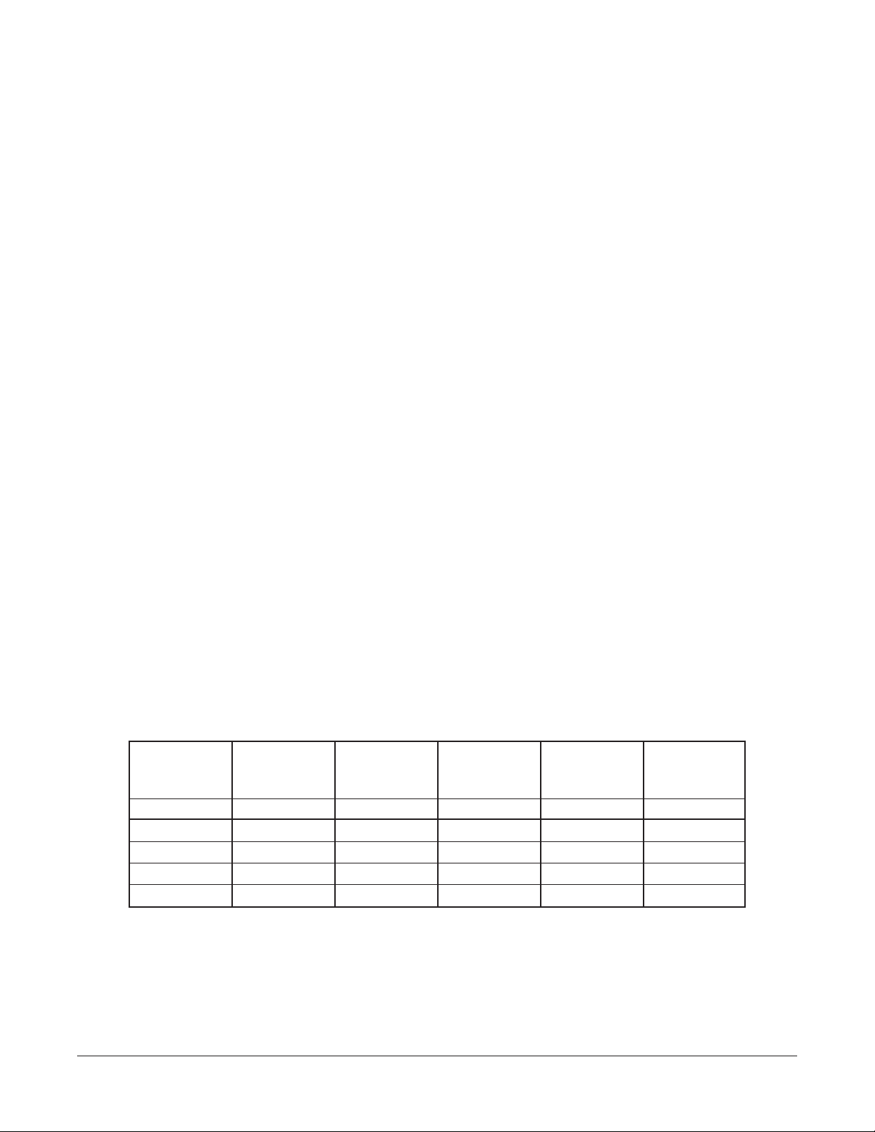
1. Screw two locating studs (found in cabinet base or stand carton) through the cabinet top flange or the stand
base bottom into bottom of oven (Fig. 1).
2. Attach each of the 4 leg assemblies to bottom of stand with 24 bolts and lockwashers (furnished) (6 per leg).
– 4 –

3. Mount the oven on top of the stand or cabinet (Fig. 1).
FRONT
BOTTOM
REAR
LOCATING STUDS
OVEN
PULL TO OPEN VENT
POWER
ON
COOL DOWN
OFF
HI
ON
LO
LIGHTS
OFF
COOK TEMPERATURE
OFF
500
450
400
200
350
300
250
COOK TIME
0
F
F
60
O
55
5
50
10
45
15
40
35
20
30
25
WARNING
TURN GAS VALVE "ON"
PUSH MASTER SWITCH TO
"ON" POSTION. IF OVEN
15 AMP
CLASS G
FUSES
DISCONNECT SUPPLY BEFORE
CHANGING FUSES, CLEANING
OR ANY OTHER SERVICE
CABINET
PL-51890
Fig. 1
Assembling the Chimney and Flue Extension
Remove the oven chimney and flue extension from the rear of the oven (motor compartment) and use the screws
provided to fasten the chimney to the top rear of the oven. The flanges on the chimney are to be positioned under
the top cover. Also attach the flue extension.
Electrical Connections
WARNING: ELECTRICAL AND GROUNDING CONNECTIONS MUST COMPLY WITH THE APPLICABLE
PORTIONS OF THE NATIONAL ELECTRICAL CODE ANSI/NFPA70 (LATEST EDITION) AND/OR OTHER
LOCAL ELECTRICAL CODES.
WARNING: DISCONNECT ELECTRICAL POWER SUPPLY AND PLACE A TAG AT THE DISCONNECT
SWITCH TO INDICATE THAT YOU ARE WORKING ON THE CIRCUIT.
Remove the wiring compartment cover on the front of the oven. Remove the appropriate knockout on the bottom
of the oven and attach the power supply conduit to the bottom of the oven.
Comply with the appropriate wiring diagram (included with this manual) when making connections to the
electrical supply lines.
Replace the wiring compartment cover and turn on the power supply.
ELECTRICAL DATA
TOTAL
3-PHASE LOADING 3-PHASE LOADING
KW KW PER PHASE KW PER PHASE 208V 240V 480V
208-240V 480V
L1-L2 L2-L3 L1-L3 L1-L2 L2-L3 L1-L3
L1 L2 L3 L1 L2 L3 L1 L2 L3
Single Oven 11 3.35 3.35 4.30 3.33 3.33 4.33 32.0 27.9 32.0 27.7 24.2 27.7 13.9 12.0 l3.9 52.8 45.8 22.9
Stacked Oven 22 6.70 6.70 8.60 6.66 6.66 8.66 64.0 55.8 64.0 55.4 48.4 55.4 27.8 24.0 27.8 105.6 91.6 45.8
The 208, 240, and 480 volt ovens covered by this manual are for connection to a 1- or 3-phase power system. Ovens leaving the factory are
wired for connection to a 3-phase power system. Wires can be changed at the installation site for connection to a 1-phase power system by altering
the wiring at the terminal block.
NOMINAL AMPERES PER LINE WIRE
3-PHASE 1-PHASE
208V 240V 480V
LEVELING
Adjust the legs to ensure that the oven racks are level in the final installed position.
– 5 –
CASTERS
If the oven is to be installed on casters, assemble the casters to the legs provided. Place the locking casters
on the front legs and non-locking casters on the rear legs.
ASSEMBLING STACKED OVENS
1. Unpack the ovens and stack kit. Position one oven on its back for access to the oven bottom, taking care
not to scratch or damage it. Attach the 4 leg assemblies with the 24 bolts and lockwashers (furnished)
(6 per leg).
2. Place lower oven (with legs) on floor and remove two 7/16" (11.1mm) diameter knockouts on each side of top
cover plus the 13/8" (35mm) diameter knockout at the right front of the top cover.
3.
Install the two locating studs (included in leg stack set) into screw plates on underside of upper oven (Fig. 2).
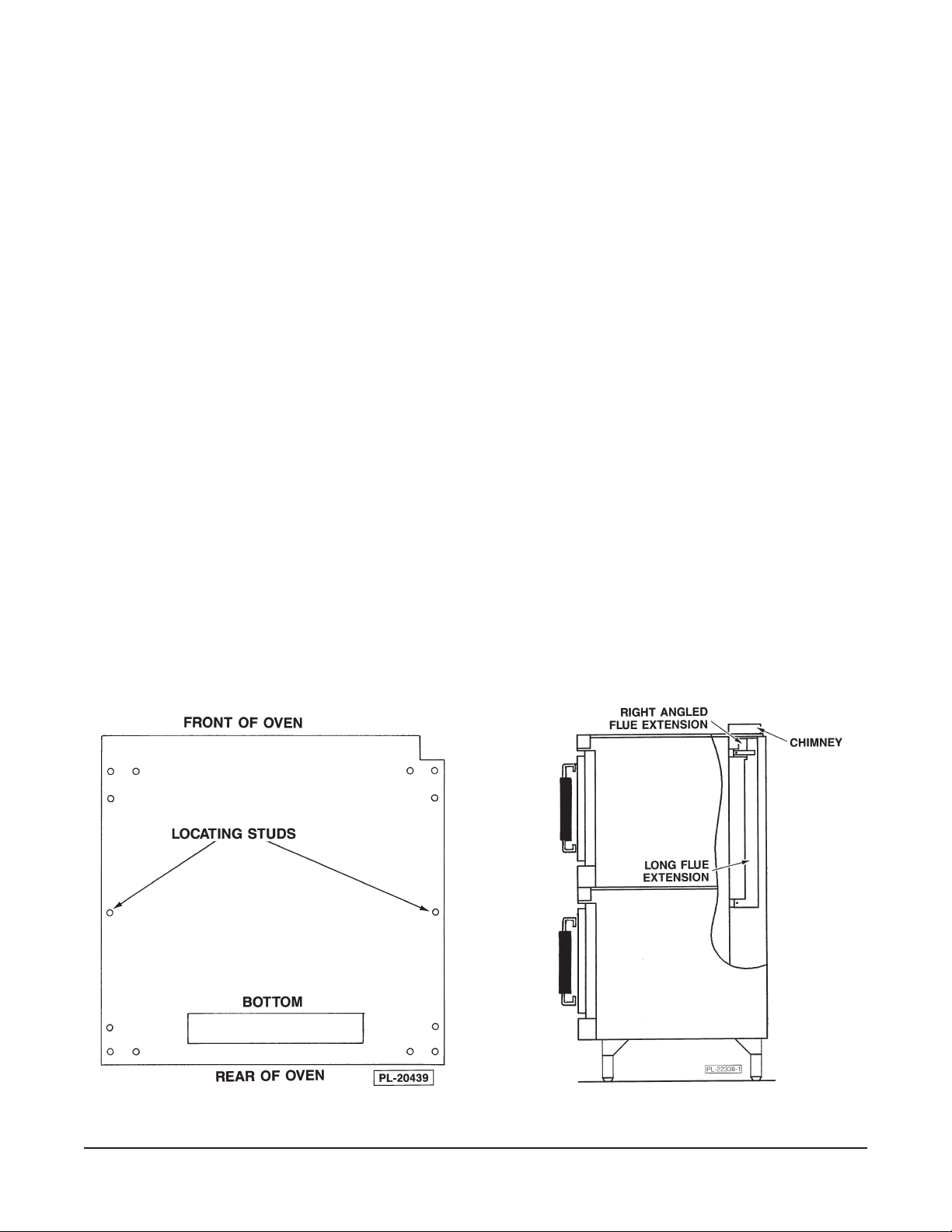
4. Remove oven chimneys stored at the rear of both ovens. Discard one chimney. Attach the remaining
chimney to the top of the upper oven (oven without legs) (Fig. 3). The flanges on the chimney are to be
positioned under the top cover.
5. Move the oven with legs to the installed position and place the upper oven on top of the lower oven using
the locating studs. Remove the wiring compartment cover from the front of both ovens. This will facilitate
routing the power leads (furnished) to the top oven, as well as attaching the 1" (25.4mm) conduit nipple and
locknut (furnished).
6. Attach the short flue extension over the exhaust vent at the rear of the upper oven. Slide the long flue
extension tube over the exhaust vent at the rear of the lower oven (Fig. 3). These extensions should direct
the exhaust fumes upward through and above the top oven.
7. Place the 1" (25.4mm) conduit nipple through the 13/8" (35mm) hole in the bottom of the top oven and the top
of the bottom oven and clamp the two ovens together with the locknut from the underside.
Fig. 2
Fig. 3
– 6 –
 Loading...